Baur KSG 200 A User manual

BAUR GmbH ▪Raiffeisenstr. 8 ▪6832 Sulz, Austria
T +43 5522 4941-0 ▪F +43 5522 4941-3 ▪www.baur.eu ▪headoffice@baur.at
User manual
Cable identification system
K S G 200 A/K S G 200 TA
phd
Figure: KSG 200 TA

Copyright © 2016
All rights reserved.
Reproduction, circulation in any form whatsoever, publishing on onlineservices or the Internet, as well as
duplication on data carriers, even in part or in an amended format, is allowed only with prior written
permission of BAUR GmbH, 6832 Sulz, Austria.
We reserve the right in the interests of our customers to make amendments as a result of further
technical development. Illustrations, descriptions and scope of supply are therefore not binding.
The names of products and companies are the trademarks or brand names of the relevant companies.

KSG 200 A/KSG 200 TA Table of contents
822-170-3 iii / 60
Table of contents
1About this manual ....................................................................................... 6
1.1 Using this manual ................................................................................ 6
1.2 Application of instructions.................................................................... 6
1.3 Structure of safety instructions ............................................................ 6
1.4 View Settings ....................................................................................... 7
1.5 Information on the screenshots and graphics used............................. 7
2For your safety............................................................................................. 8
2.1 Intended use ........................................................................................ 8
2.2 Instructions to the user......................................................................... 8
2.3 Avoiding dangers, taking safety measures.......................................... 9
2.3.1 Operation only in a technical secure state............................. 9
2.3.2 No operation during condensation......................................... 9
2.3.3 No operation in areas with risk of explosion and fire...........10
2.3.4 Dangers when working with electric voltage........................10
2.4 Special personal protection equipment.............................................. 14
3Product information .................................................................................. 15
3.1 Device types ...................................................................................... 15
3.2 Transmitter......................................................................................... 15
3.2.1 Connection cables................................................................ 17
3.2.2 Connection set to connect to live LV cables (KSG 200 TA) 17
3.3 Receiver............................................................................................. 18
3.4 Charger.............................................................................................. 19
3.5 Power supply ..................................................................................... 20
3.5.1 Battery operation.................................................................. 20
3.5.2 DC 12 V power supply ......................................................... 20
3.6 Markings on the system..................................................................... 21
3.6.1 Rating plates........................................................................ 21
3.6.2 Safety and information signs on the system........................22
4Technical data............................................................................................ 23
5Operating the system................................................................................ 25
5.1 Cable identification with KSG 200 A..................................................25
5.2 Switching on and off the system........................................................26

Table of contents KSG 200 A/KSG 200 TA
iv
/ 60 822-170-3
5.3 Display ............................................................................................... 26
5.3.1 Symbols ............................................................................... 26
5.3.2 Infocodes and their meaning................................................ 28
5.4 Standard and expert mode ................................................................ 29
6Connecting the system............................................................................. 30
6.1 Signal coupling types......................................................................... 30
6.2 Setting up the system ........................................................................ 30
6.3 Checks to perform before commissioning .........................................30
6.4 Important information on connecting the flexcoupler......................... 31
6.5 Connecting the system to de-energised cables................................. 31
6.5.1 Safety instructions................................................................ 31
6.5.2 Ensure there is no voltage at the work place....................... 31
6.5.3 Connecting the system for galvanic signal coupling............32
6.6 Connecting the system to live cables (KSG 200 TA).........................35
6.6.1 Safety instructions................................................................ 35
6.6.2 Connecting the system for galvanic signal coupling............36
6.6.3 Connecting the system for inductive signal coupling
(optional) .............................................................................. 37
6.7 Applying the flexcoupler with flexible rod........................................... 38
6.8 Securing the test area........................................................................ 39
6.8.1 Securing the test area during cable identification on live
cables................................................................................... 39
7Cable identification.................................................................................... 40
7.1 Calibrating the system and identifying cables ...................................40
7.2 Evaluating measurement results ....................................................... 41
7.3 Carrying out the measurement in expert mode .................................42
7.3.1 Activating the expert mode .................................................. 43
7.3.2 Adjusting the gain................................................................. 43
7.3.3 Deactivating the expert mode ..............................................43
8Current measurement ............................................................................... 44
9Phase determination (optional)................................................................ 45
10 Completing the cable identification......................................................... 47
10.1 Safety instructions.............................................................................. 47
10.2 Dismantling the test structure ............................................................48
11 Maintenance............................................................................................... 49
11.1 Safety instructions.............................................................................. 49
11.2 Cleaning system components............................................................ 49
11.3 Charging the transmitter battery........................................................ 50
11.4 Charging the receiver......................................................................... 50

KSG 200 A/KSG 200 TA Table of contents
822-170-3 v / 60
11.5 Charging battery via the vehicle charge cable................................... 51
11.6 Check if the charger is damaged.......................................................51
11.7 Testing fuses in safety measurement cables (KSG 200 TA).............52
11.8 Replacing fuses in safety measurement cables (KSG 200 TA) ........ 53
12 Faults and corrective measures............................................................... 54
12.1 Safety instructions.............................................................................. 54
12.2 Troubleshooting ................................................................................. 54
13 Transportation and storage...................................................................... 55
13.1 Transporting the system .................................................................... 55
13.2 Storing the system............................................................................. 55
14 Warranty and After Sales.......................................................................... 56
15 Disposal...................................................................................................... 56
15.1 Disposing of the system..................................................................... 56
15.2 Disposing of rechargeable battery pack and charger........................56
16 Delivery scope and options...................................................................... 57
17 Index............................................................................................................ 58

About this manual KSG 200 A/KSG 200 TA
6
/ 60 822-170-3
1.1 Using this manual
This user manual contains all necessary information that is needed for the commissioning and
operation of the described product.
Read this user manual completely before operating the product for the first time.
Consider this user manual to be a part of the product and store it in an easily accessible
location.
If this user manual is lost, please contact BAUR GmbH or your nearest BAUR
representative (http://www.baur.eu/baur-worldwide).
1.2 Application of instructions
This user manual applies for cable identification systems with battery:
KSG 200 A
KSG 200 TA
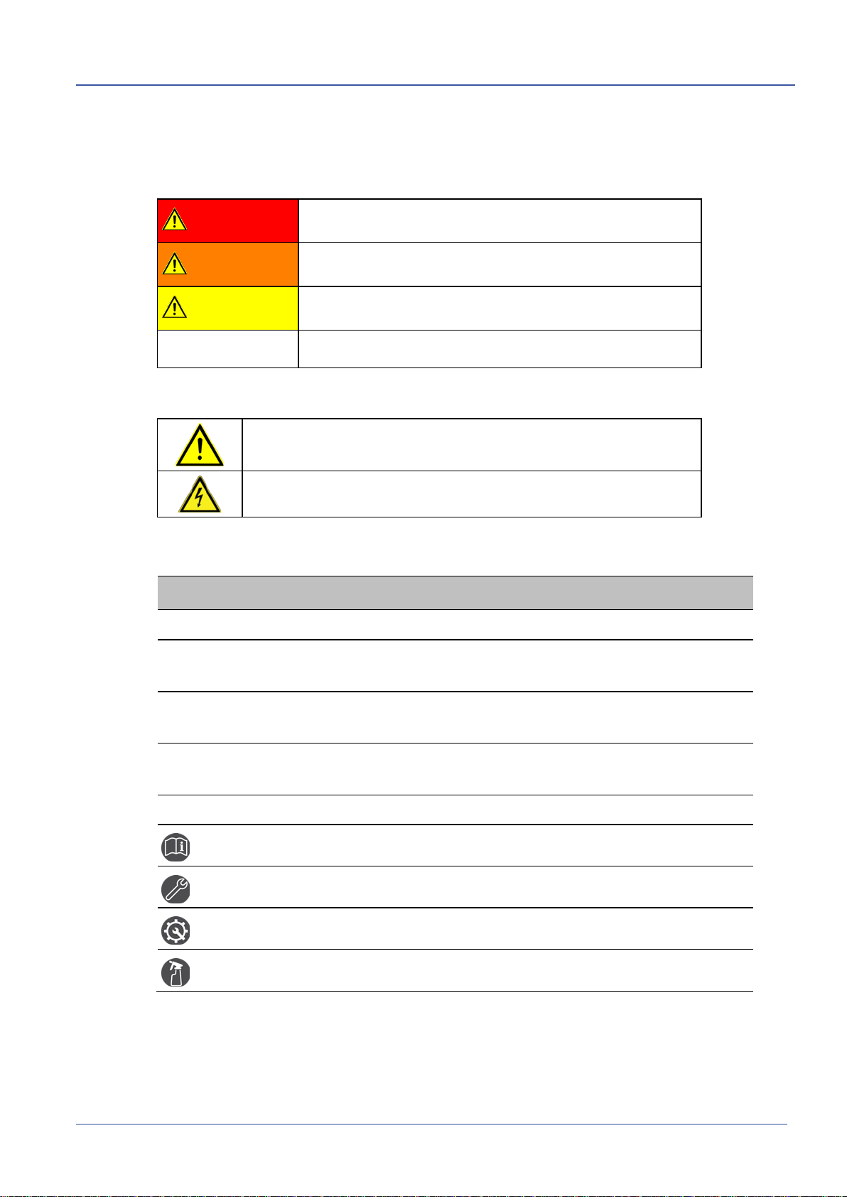
1.3 Structure of safety instructions
The safety instructions in this user manual are presented as follows:
Danger
symbol
SIGNAL WORD
Type of danger and its source
Possible consequences of violation.
Measure to prevent the danger.
If a dangerous situation could arise at a specific step, the safety instruction is displayed
immediately before this dangerous step and is shown as follows:
SIGNAL WORD
Type of danger and its source. Possible consequences of violation.
1. Measure to prevent the danger.
1 A
BOUT THIS MANUAL
KSG 200 A/KSG 200 TA About this manual
822-170-3 7 / 60
Danger levels
Signal words in the safety instructions specify the danger levels.
DANGER Will lead to severe injuries or death.
WARNING May lead to severe injuries or death.
CAUTION May lead to light to moderate injuries.
NOTICE May lead to material damage.
Danger symbols
General danger
Risk of electric shock
1.4 View Settings
Symbol Meaning
You are requested to perform an action.
1.
2. ...
Perform the actions in this sequence.
a.
b. ...
If an operation consists of several operating steps, they are specified with "a, b, c".
Perform the operating steps in this sequence.
1
2 ...
Numbering in the legend
List
Indicates further information on the topic.
Indicates tools required for the subsequent tasks.
Indicates spare parts required for the subsequent tasks.
Indicates required cleaning agents.
1.5 Information on the screenshots and graphics used
The screenshots and graphics used are intended to illustrate the procedure and may therefore
differ slightly from the actual state.

For your safety KSG 200 A/KSG 200 TA
8
/ 60 822-170-3
All BAUR devices and systems are reliable and are manufactured as per state-of-the-art
technology. The individual parts and the finished devices are subject to continuous testing by
our qualified personnel as part of our quality assurance system. Each device is fully tested
before delivery.
However, the operational safety and reliability in practice can be achieved only when all
necessary measures have been taken. The responsible body1and operator2of the device or
system are responsible for planning these measures and monitoring their implementation.
Before operating the device or system you should read and understand this user manual and
the user manuals of all integrated devices.
2.1 Intended use
The cable identification system from the KSG series is used to identify single and multi-core
cables in a cable bundle or cable loom:
KSG 200 A – for de-energised cables
KSG 200 TA – for live cables, measurement category CAT IV/600 V
If the system is not used without observing this condition, safe operation cannot be
guaranteed. The user is liable for any damage to persons and property resulting from incorrect
operation!
Proper use also includes
Compliance with all instructions in this user manual and in the user manuals of integrated
and operated devices,
Compliance with the technical data and connection requirements given on the rating plate
and in the user manual (applies for all devices in the system),
Compliance with the inspection and maintenance instructions.
2.2 Instructions to the user
The product may only be operated by authorised and trained electrical engineers. An electrical
engineer is a person who, owing to his professional education (electrical engineering),
knowledge, experience and acquaintance with the applicable standards and regulations, can
assess the tasks assigned to him and detect possible dangers.
In addition, the user must have:
Knowledge of the technical equipment and operation of KSG 200 A/KSG 200 TA
Knowledge of plant engineering (cable types, switchboard plant, etc.).
1Responsible body is the person or group that is responsible for the safe operation of the device and its
maintenance (EN 61010-1, 3.5.12).
2Operator is the person who uses the device for its intended purpose (according to the definition of user in
compliance with EN 61010-1, 3.5.11).
2 F
OR YOUR SAFETY

KSG 200 A/KSG 200 TA For your safety
822-170-3 9 / 60
2.3 Avoiding dangers, taking safety measures
When installing the test system and operating KSG 200 A/KSG 200 TA observe the
following rules and guidelines:
Accident prevention and environment protection rules applicable for your country
Safety instructions and regulations of the country where KSG 200 A/KSG 200 TA is
being used (according to the latest version)
EU/EFTA countries: EN 50110 “Operation of electric systems”
Other countries: Standards for operating electric systems applicable in your country
If necessary, other national and international standards and guidelines in accordance
with the latest applicable version
Local safety and accident prevention regulations
Operational insurance association regulations (if any)
2.3.1 Operation only in a technical secure state
Safety, function and availability depend on the proper condition of the system.
Operate the system and the integrated devices only in a technical perfect condition.
In case of damage and malfunction, immediately stop the system, mark it accordingly and
have the faults rectified by appropriately qualified and authorised personnel.
Comply with the inspection and maintenance conditions.
Use only accessories and original spare parts recommended by BAUR. The use of spare
parts, accessories and special facilities that are not tested and approved by BAUR could
adversely affect the safety, function and characteristics of the product.
2.3.2 No operation during condensation
Condensation can form in devices and systems due to temperature fluctuations and high air
humidity, which in some components can result in leakage currents, flashovers and
short-circuits.
Maximum danger arises when relatively high air humidity and temperature fluctuations occur
in a device consecutively, which is the case when storing the system or device in an unheated
room or when placed outdoors, for example. When the system or device is then exposed to a
high ambient temperature, the cold device surfaces cool the air in the immediate vicinity, which
leads to formation of condensation even inside the device.
During this process, two factors are crucial:
The higher the relative air humidity, the faster the dew point is reached and water is
condensed.
The higher the temperature difference between the surfaces and the ambient air, the
stronger the tendency for condensation.
Always prevent condensation in devices. Temper the device and system before and during
the measurements so that no condensation occurs.

For your safety KSG 200 A/KSG 200 TA
10
/ 60 822-170-3
2.3.3 No operation in areas with risk of explosion and fire
Measurements in direct contact with water, in environments with explosive gases and in areas
with fire risks are not permitted. Possible danger areas include e.g. chemical factories,
refineries, paint factories, paint shops, cleaning plants, mills and stores of milled products,
tank and loading plants for combustible gases, liquids and solid matter.
2.3.4 Dangers when working with electric voltage
During cable identification with systems from the KSG series, a voltage up to 300 V is
generated that is connected to the cable to identify via a connection cable. In addition, with
KSG 200 TA, you can carry out cable identification on live cables. Operating personnel need to
pay special attention and must be very careful while working with electric voltage.
Commissioning and operation of KSG 200 A/KSG 200 TA are permitted only in compliance
with the EN 50110 (EU/EFTA countries) or with standards applicable in your country.
Before commencing work, the operator must assess the risks for the specific working
conditions. Protective measures are based on the risk assessment and must be followed
at the workplace.
Other safety information:
Cable identification on de-energised cables (on page 10)
Cable identification on live cables (on page 11)

KSG 200 A/KSG 200 TA For your safety
822-170-3 11 / 60
Cable identification on de-energised cables
Observe 5 safety rules
Comply with the following safety rules before beginning tasks in and on the electrical plant:
1. Disconnect the test object.
2. Secure against re-connection.
3. Verify absence of operating voltage.
4. Earth and short all phases.
5. Provide protection against adjacent live parts.
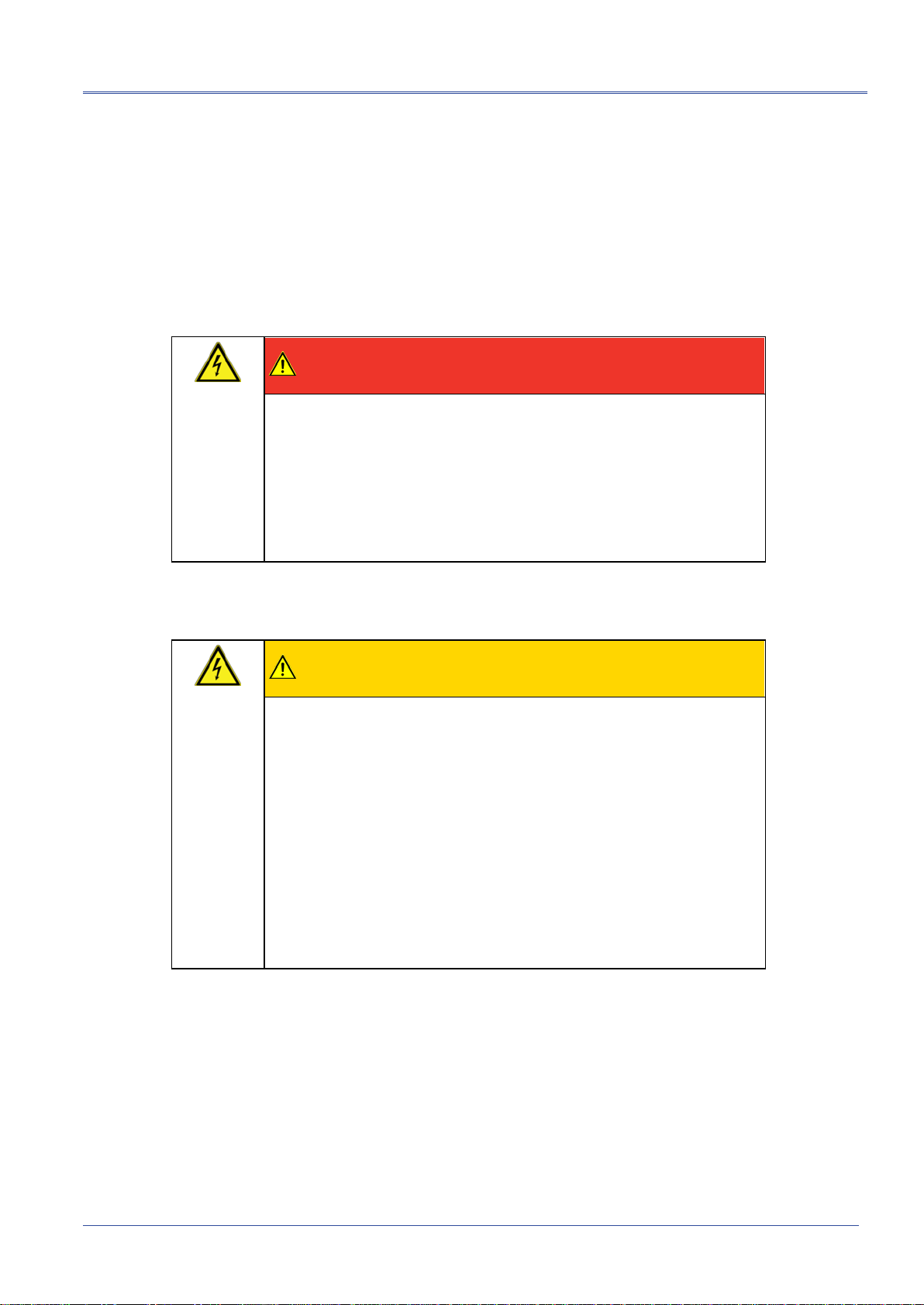
DANGER
Dangerous electric voltage
Danger to life or risk of injury due to electric shock. Danger of burn
injuries and electro-ophthalmia due to arcing fault.
Use suitable personal protective equipment to protect against arcing
faults.
Cover the adjacent live parts with insulating covering material.
Cordon off all metal parts, e.g. lighting masts, at the terminals of the
object under test or insulate them with insulating safety plates.
Connect the transmitter and receiver as described in this user
manual.
Use only undamaged connection cables.
Secure the connection points and the far end of the cable to be
identified.
Before removing the safety measures, discharge, earth and
short-circuit all live parts.

For your safety KSG 200 A/KSG 200 TA
12
/ 60 822-170-3
Cable identification on live cables
You can carry out cable identification on live cables only with KSG 200 TA. Note that working
on live parts and plants can be fundamentally dangerous.
When connecting the system to the cable that is to be identified, the operator can come close
to live parts during preparation and while performing the cable identification. In so doing, there
is danger of touching the active parts directly or indirectly.
DANGER
Working in the vicinity of adjacent live parts
Danger to life or risk of injury due to electric shock.
The KSG 200 TA cable identification system may be used only in
electric circuits of the measurement category CAT IV/600 V .
Mains nominal voltage (outer phase-neutral phase) DC or
ACrms: 600 V
Use the cable identification on live cables only with the supplied
safety measurement cables.
Without the safety measurement cables, the KSG 200 TA cable
identification system has the measurement category 0 and should
not be used on live cables.
Maintain safety distances. Safety distances depend on the voltage
level, plant model, personnel qualification and available space
(EN 50110).
During connection, implementation and monitoring of the
measurement, protection must be guaranteed for all plant parts,
either
through safety devices, insulating cover material
or by adhering to the necessary safety distances. Safety
distances depend on the voltage level, plant model, personnel
qualification and available space.
In this regard, comply with EN 50110 or the applicable standards in
your country as well as the relevant national and local accident
prevention regulations.
Working in the vicinity of open cables or faulty systems is forbidden.
Notify the responsible authorities immediately.
Use suitable personal protective equipment to protect against arcing
faults.
To assess the local conditions adequately, provide sufficient lighting
at the work place.
KSG 200 A/KSG 200 TA For your safety
822-170-3 13 / 60
Dangers during cable cutting after cable identification
Among other things, cable identification is used to determine the right cable before cutting an
electrical connection. This helps you avoid cutting a wrong, or live cable accidentally.
In spite of the latest identification procedure, in particular in cable clusters or due to the
identification being affected by adjacent cables that are in operation, etc. it is not always
possible to clearly determine the de-energised condition of a specific cable that you want to
work with. If no current can be ascertained by measuring the current with KSG systems, it does
not mean that the cable is disconnected and can be safely cut.
DANGER
Dangerous voltage in cables
Danger to life or risk of injury due to electric shock; damage to property
when cables are cut during incorrect cable identification.
Only use cable cutters in compliance with EN 50340 or cable spiking
tools.
Follow the safety instructions in the user manual for the cable cutter
or cable spiking tool used.
Dangers when working with the charger
CAUTION
Dangerous electric voltage on the charger
Risk of injury due to electric shock.
The charger is an electrical equipment that feeds voltages and currents
that are dangerous for humans.
Only use the supplied charger for KSG 200 A/KSG 200 TA.
Protect the charger against humidity.
Use the charger only in dry spaces.
If the charger is damp for any reason, do not connect it to the mains
voltage under any circumstances.
If the charger is damp during the charging process, do not touch it.
First disconnect it from the mains voltage.

For your safety KSG 200 A/KSG 200 TA
14
/ 60 822-170-3
2.4 Special personal protection equipment
Personal safety equipment based on the risk assessment for the relevant working conditions is
part of the KSG 200 A/KSG 200 TA safety concept.
Observe the national safety regulations and your company's working and operating
instructions.
Dependent on the conditions of the work place, use the following safety equipment:
Protection against electrostatic charging,
crushing, slipping and other accidents: Safety footwear
Protection against electrical hazards (arcing
fault): Certified safety clothing
Hard hat with visor
Insulating protective gloves
LV HRC fuse handle with sleeve
Protection against noise: Ear protection
Protection against dangers from road traffic: High visibility vest according to EN 471
(Protection class 2) or according to the
applicable standards in your country for high
visibility clothing for commercial use.
Important: No high visibility vest during tasks
with risk of arcs!
Hand protection: Safety gloves

KSG 200 A/KSG 200 TA Product information
822-170-3 15 / 60
3.1 Device types
The cable identification system KSG 200 A is available in two types:
KSG 200 A for cable identification on de-energised cables
KSG 200 TA for cable identification on live cables (CAT IV/600 V)
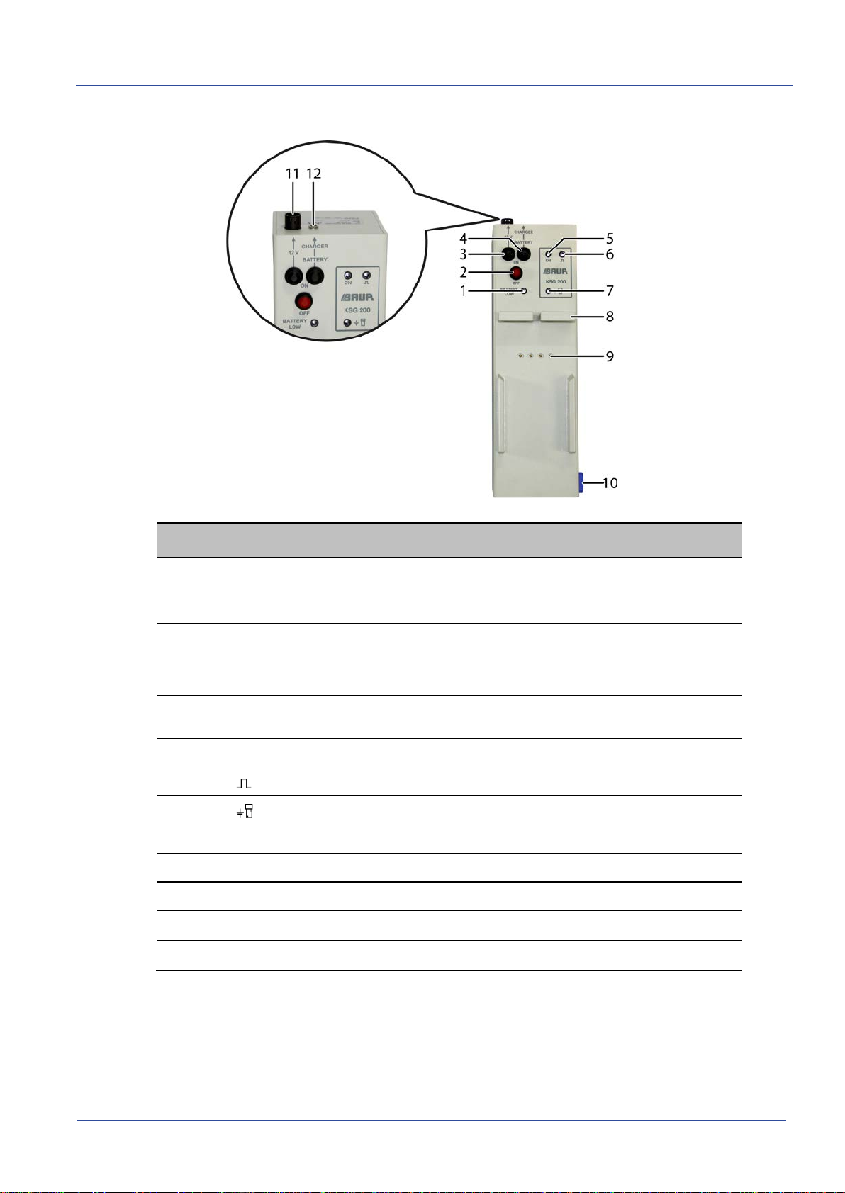
3.2 Transmitter
The transmitter contains a pulse capacitor that is charged and later discharged via the cable
that is to be identified. The charging and discharging of the pulse capacitor is controlled
temporally by a microprocessor. A holder for the receiver has been provided on the
transmitter. While inserting the receiver in the transmitter holder, an electrical connection is
established between both devices and following actions can be performed automatically:
The cable identification system is moved to the initial state.
The super capacitors for power supply to the receiver are charged.
Data between devices is exchanged via a serial interface.
Note: At room temperature (approx. 19 – 21 °C), the battery must be charged every 2
months. Intervals for higher storage temperatures: Chapter Storing the system (on page 55)
3 P
RODUCT INFORMATION
Product information KSG 200 A/KSG 200 TA
16
/ 60 822-170-3
No. Element Function
1 LED Battery LOW Lights up when the battery level is low
If the charger is not connected, the transmitter is automatically
switched off after 10 to 20 minutes.
2 OFF button Switches off the transmitter
3 ON – 12 V button Switches on the transmitter when it receives power via the DC
12 V connection
4 ON – Battery Charger button Switches on the transmitter when it receives power via the
rechargeable battery
5 LED ON Indicates whether the transmitter is receiving power
6 LED Lights up in the current pulse cycle
7 LED Lights up when the receiver is charging
8 Holder for the receiver Is used to insert the receiver for charging and calibration
9 Contacts Are used to connect the transmitter and the receiver
10 Bayonet port Is used to connect the connection cable to the transmitter
11 12 V port Is used to connect to a 12 V vehicle battery
12 Charger port Is used to connect the charger to the transmitter
KSG 200 A/KSG 200 TA Product information
822-170-3 17 / 60
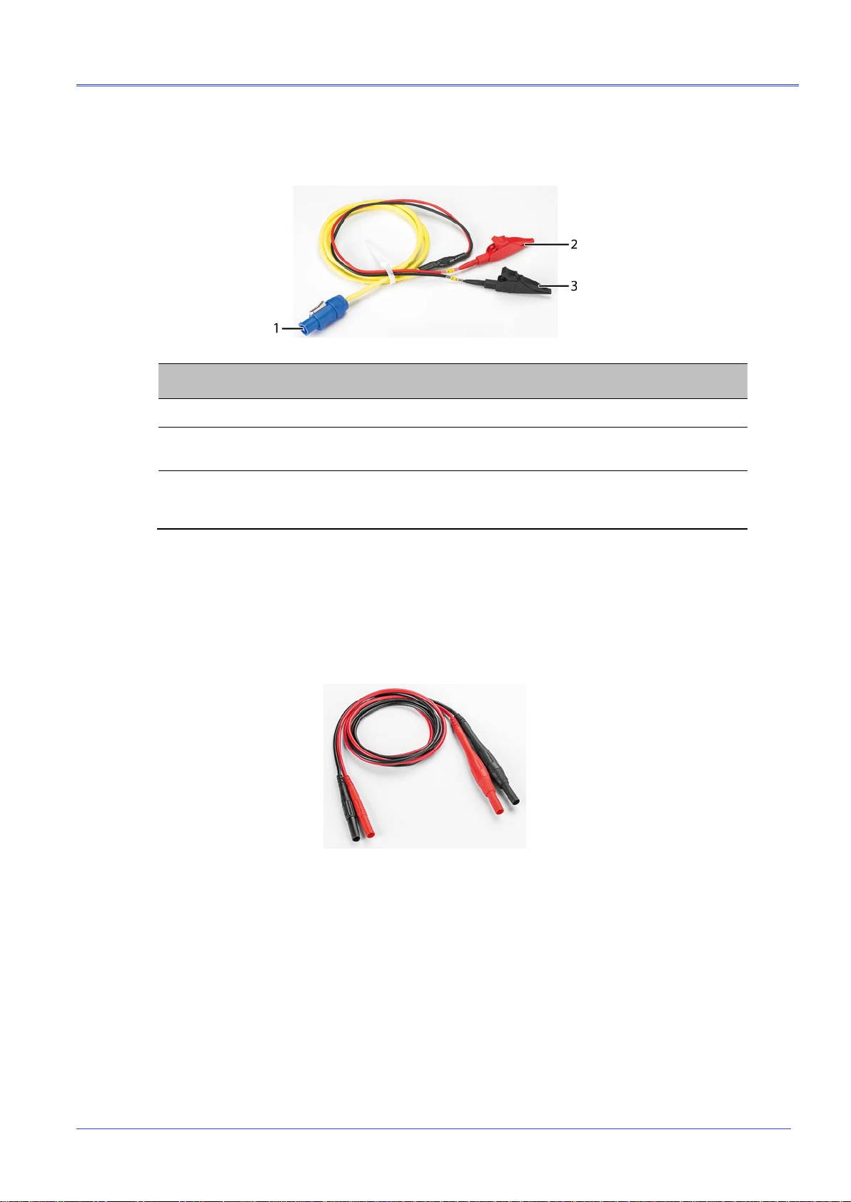
3.2.1 Connection cables
No. Element Function
1 Bayonet port Is used to connect the connection cable to the transmitter
2 Red connection clip
(transmitter plus pole) Is used to connect the transmitter to the cable or phase that is
to be identified
3 Black connection clip
(transmitter minus pole) Is used to connect the transmitter to the substation earth or to
the second pha
se for the return circuit of the connected current
pulse
3.2.2 Connection set to connect to live LV cables (KSG 200 TA)
The connection set to connect to live LV cables comprises of
2 safety measuring cables, CAT IV/600 V
2 fuses F 7 A, 50 kA @ AC 600 V (integrated in safety measuring cable)

Product information KSG 200 A/KSG 200 TA
18
/ 60 822-170-3
3.3 Receiver
The receiver with the attached flexcoupler is used to record and evaluate the current pulses
and to display the measurement results.
The flexcoupler is available in 2 sizes:
Ø 150 mm
Ø 250 mm
No. Element Function
1 Flexcoupler Is used to record the electromagnetic field around the cable
that is to be identified
2 Display Displays information on the measurement and measurement
results
3 button Displays the infocode and starts the current measurement
4 button Increases the gain in expert mode
5 button Decreases the gain in expert mode
6 button Starts the calibration and displays the signal amplitude
7 Contacts Are used to connect the transmitter and receiver in the holder
8 Infocodes Are used to explain the displayed infocodes

KSG 200 A/KSG 200 TA Product information
822-170-3 19 / 60
3.4 Charger
The supplied plug-in charger is used to charge the NiMH rechargeable battery pack: 10-12
cells, 2.8 - 7.0 Ah.
Technical data
Output voltage 10.5 – 20 V DC; 1.0 A Rated capacitance 2.8 – 7.0 Ah
Input voltage 100 – 240 V, 50/60 Hz Charging current Main charging: 1,000 mA
Charging the fully discharged
battery: 250 mA
Float charge: 38 mA
Number of cells 10 Charging time Depends on the battery
charge status
Complete charging: approx.
4.5 – 5 h
Ambient temperature 0 – 40 °C Fuse T 2.0 A
Storage temperature -40 to +70 °C
LED display
Display Description
Constant Main charging mode: Normal status after battery contact
Flashing (low flash frequency) Float charge: The battery is full. Switchover to float charge takes place
automatically.
Flashing (high flash frequency) Battery total discharge: Battery voltage ≤10.5 V

Product information KSG 200 A/KSG 200 TA
20
/ 60 822-170-3
3.5 Power supply
The KSG 200 A/KSG 200 TA transmitter can be supplied voltage in various ways:
via the integrated battery
via a DC 12 V vehicle battery
The receiver is equipped with super capacitors for power supply and is automatically charged
in the transmitter holder when the transmitter is switched on. After it is fully charged, the
receiver can be used for approx. 1 hour.
3.5.1 Battery operation
The KSG 200 A/KSG 200 TA transmitter is equipped with a NiMH rechargeable battery pack.
Technical data
Voltage 12 V Battery life 2.5 - 3.5 h
Capacitance 4.2 - 5 Ah Number of cells 10
If the transmitter battery level is low, the Battery LOW LED lights up. The transmitter is
automatically switched off after 10 to 20 minutes.
Note: The transmitter cannot be supplied with power for operation via the charger.
Further information: Chapter Charging the transmitter battery (on page 50)
3.5.2 DC 12 V power supply
The 12 V port on the transmitter is used to connect to a 12 V vehicle battery.
Fuse: T 8 A
This manual suits for next models
1
Table of contents
Other Baur Test Equipment manuals


