Baur PGK 50 User manual
0-1
Operating Instructions
High Voltage Testing Sets
PGK 50 and PGK 80
For High Voltage Tests up to:
50 kV DC (= PGK50) and 80 kV DC (= PGK80)
Ident No. 822-006 01/00
BAUR Prüf- und Messtechnik GmbH
Raiffeisenstrasse 8, A-6832 Sulz / Austria Tel +43 / 55 22 / 49 41-0
Fax +43 / 55 22 / 49 4 13
e-mail: headoffice@baur.at
internet: http://www.baur.at

0-2
0-3
For fast finding of important information the corresponding text
passages are marked with symbols (symbols not stated here are
self-explaining):
More and special information concerning the respective subject are
available from BAUR.
Important unit information!
In any case, read carefully!
Important information text.
Observe info signs!
☞
© BAUR Prüf- und Messtechnik GmbH,
A-6832 Sulz /Austria
All rights reserved.
No part of this publication may be reproduced, transmitted, stored
in a data processing system or translated into another language
without the written permission of BAUR / Sulz,Austria.
In the interest of our customers we reserve the rights for
modifications due to technical progress.
Illustrations, descriptions and delivery content are therefore not
binding.
Guide to this Operating Instruction, Copyright, Preface, Safety Precautions
Guide to this Operating Instruction
This manual contains all information necessary for the correct
handling and use of the High Voltage Testing Sets PGK50 and
PGK80. Before using the PGK, please read carefully this Operating
Instruction. If you have any question, please contact directly:
BAUR Prüf- und Messtechnik GmbH, Raiffeisenstrasse 8
A-6832 Sulz /Austria
or refer to your nearest BAUR representative.
Subject to modification!
Tel +43 / 55 22 / 49 41-0
Fax +43 / 55 22 / 49 41 3
- The High Voltage Testing Sets PGK50 and PGK80 are built in
accordance with today’s state of engineering and is safe to
operate. Individual components and the finished unit are
inspected continually by our qualified staff within the framework
of our QualityAssurance Provisions. Each unit is subjected to
thorough testing prior to shipment.
Preface
Copyright
Safety Precautions
Continued
0-4
Safety Precautions, Warranty
Safety Precautions, Continued
- It is imperative to every person who is involved with the
installation, start-up, operation and maintenance to have read
and understood the complete Operating Instruction.
- It is the responsibility of the customer to ensure that only
authorized persons may be allowed to use the PGK.
The user
- is qualified and properly instructed and has the necessary
experience.
- knows the relevant standards, accident prevention rules
and operating conditions.
- is able to carry out the necessary operations and is aware of
the possible dangers involved.
- must immediately inform his superior about any conditions of
the unit that could affect safety.
-The High Voltage Testing Sets PGK50 and PGK80 are
exclusively for testing the dielectric strenght of electrical
equipment with a maximum capacity of 20 µF.
Any other or additional use is deemed to be in contravention of
the intended use. The manufacturer shall not be liable for
damage resulting from any such use. In such a case the risk
shall be borne solely by the user.
The local safety and accident prevention regulations are
always applicable to the operation of the PGK50 and PGK80.
Please read now
and avoid damage
and injury later!
Only authorized personnel!
Use the PGK50
and PGK80 as directed!
☞
At the customer’s written request we undertake to repair or replace
at our discretion and as quickly as possible all parts that become
faulty or useless as the demonstrable result of poor material, faulty
design or defective execution.
The 12 month warranty time starts with delivery.
We shall bear the costs of any faulty parts requiring replacement,
but not the costs of transport to us and back to the customer, nor the
costs of packing and insurance! We shall not be liable for any
damage resulting from normal wear and tear, improper handling,
non-observance of Operating Instruction and safety regulations.
We shall also refuse to accept any liability if the customer carries out
repairs or changes to the unit himself or has others carry out them!
The warranty does not cover damage in transit, batteries, fuses and
any readjustments in accordance with the Operating Instruction!
We draw attention in addition to the ‘General Terms of Sales and
Delivery’ of:
Warranty
12 month warranty time
BAUR Prüf- und Messtechnik GmbH, Raiffeisenstrasse 8
A-6832 Sulz /Austria

0-5
Contents
Contents
1. Product Information .........................................................................1-1
Design and function .................................................................... 1-2
Discharge device ........................................................................ 1-3
Important key commands............................................................ 1-4
Display and Operating Elements................................................. 1-6
PGK Interfaces ........................................................................... 1-7
Technical Data - PGK50 and PGK80 .......................................... 1-8
PGK Load Curves....................................................................... 1-9
2. Packing and Shipping......................................................................2-1
Damage during transport ............................................................ 2-1
Items included............................................................................. 2-2
3. Preparations for a Test.....................................................................3-1
Connect test object ..................................................................... 3-2
Set timer ..................................................................................... 3-4
Connect plotter ........................................................................... 3-5
Connect EMERGENCY-STOP switch, electric gate, signal lamps 3-
6
4. Performing High Voltage Test .........................................................4-1
Switch on PGK and perform high voltage test............................. 4-2
Determine resistance value ........................................................ 4-4
Switch off PGK............................................................................ 4-5
5. Servicing ...........................................................................................5-1
Set mains voltage ....................................................................... 5-2
Timer - activate acoustic signal only ........................................... 5-3
Check transient protection resistor.............................................. 5-4
6. Spare Parts / Wearing Parts ............................................................6-1
7. Index..................................................................................................7-1

0-6
Notes
○○○ ○○○○○○○○○○○○○○○○○○○○○○○○○○○○○○○○○○○
○○○○○○○○○○○○○○○○○○○○○○○○○○○○○○○○○○○○○○
○○○ ○○○○○○○○○○○○○○○○○○○○○○○○○○○○○○○○○○○
○○○ ○○○○○○○○○○○○○○○○○○○○○○○○○○○○○○○○○○○
○○○ ○○○○○○○○○○○○○○○○○○○○○○○○○○○○○○○○○○○
○○○○○○○○○○○○○○○○○○○○○○○○○○○○○○○○○○○○○○
○○○ ○○○○○○○○○○○○○○○○○○○○○○○○○○○○○○○○○○○
○○○ ○○○○○○○○○○○○○○○○○○○○○○○○○○○○○○○○○○○
○○○○○○○○○○○○○○○○○○○○○○○○○○○○○○○○○○○○○○
○○○ ○○○○○○○○○○○○○○○○○○○○○○○○○○○○○○○○○○○
○○○○○○○○○○○○○○○○○○○○○○○○○○○○○○○○○○○○○○
○○○○○○○○○○○○○○○○○○○○○○○○○○○○○○○○○○○○○○
○○○○○○○○○○○○○○○○○○○○○○○○○○○○○○○○○○○○○○
○○○ ○○○○○○○○○○○○○○○○○○○○○○○○○○○○○○○○○○○
○○○○○○○○○○○○○○○○○○○○○○○○○○○○○○○○○○○○○○
○○○○○○○○○○○○○○○○○○○○○○○○○○○○○○○○○○○○○○
○○○ ○○○○○○○○○○○○○○○○○○○○○○○○○○○○○○○○○○○
○○○○○○○○○○○○○○○○○○○○○○○○○○○○○○○○○○○○○○
○○○ ○○○○○○○○○○○○○○○○○○○○○○○○○○○○○○○○○○○
○○○○○○○○○○○○○○○○○○○○○○○○○○○○○○○○○○○○○○
○○○○○○○○○○○○○○○○○○○○○○○○○○○○○○○○○○○○○○
○○○○○○○○○○○○○○○○○○○○○○○○○○○○○○○○○○○○○○
○○○ ○○○○○○○○○○○○○○○○○○○○○○○○○○○○○○○○○○○
1-1
1. Product Information
1. Product Information
Overview
This section describes all necessary information about your High
Voltage Testing Set PGK50/80.
Topic Page
Design and function 1-2
Discharge device 1-3
Important key commands 1-4
PGK Interfaces 1-7
Technical Data - PGK50 and PGK80 1-8
PGK Load Curves 1-9
This section contains the following topics:
1-2
1. Product Information
Design and function
General view
of PGK
0
246810 12 141618
20
22
24
26
28
30
100mA
10mA
1mA100µA
10µA
1µA
F1
F2
PGK
T/ min UDC
Umax
B
0
20
4
0
6
0
8
0
1
0
0
U [kV]
I
00
0
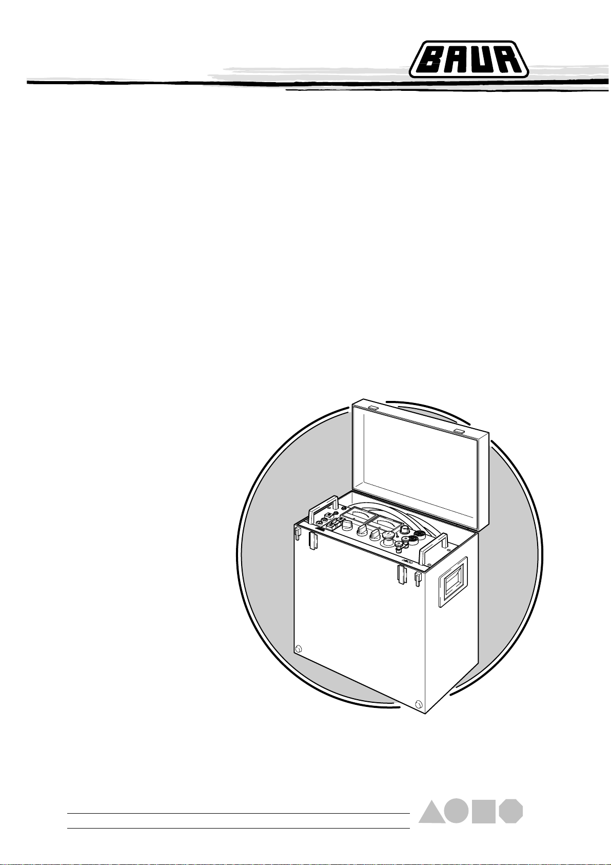
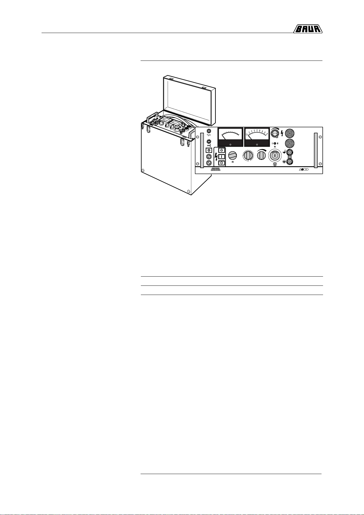
A compact and light weight
High Voltage Testing Set The primary area of application is in-field testing of cables. High
voltage is generated by a high voltage transformer and a voltage
multiplier. Thanks to an operating frequency of 20kHz small
dimensions are possible. Packaged in a handy carrying case with
handles and carrying strap, the PGK units are portable and
therefore equipped for field applications.
Test voltages Type PGK50 PGK80
Max. test voltage 50 kV DC 80 kV DC
at an output current of: 2 mA 0.8 mA
Features - automatic, SF6insulated discharge unit
- timer (0-30 minutes)
- connection for an electric gate, emergency-stop switch and
external warning lamps
- connection for Y/t plotter for recording the current flow
- shielded high voltage cables with clamps for connecting the test
object
- integrated thermal switch
- carrying case with handles, foldable mounting legs and cable
compartment

1-3
1. Product Information
Discharge device
The discharge device of the PGK50/80 consists of a pressure tank
(overpressure = 3 bar) filled with insulatig gas (SF6sulphur
hexafluoride).A NC-contact and a discharge resistor are installed in
the pressure tank. The discharge resistance is 69kWincluding
transient protection and is configured for a maximum surge power
of 8.000Ws.
The discharge device works automatically and independent of
instrument position and remains activated even at power
failure.The response of the discharge device is a loud switching
noise.
Diagram 1 indicates the maximum permissable load capacitance
depending upon the selected test voltage.
Diagram 1
0
2.5
5
7.5
10
12.5
15
17.5
20
22.5
25
0 5 10 15 20 25 30 35 40 45 50 55 60 65 70 75 80
Test voltage in kV
During two discharges: Observe 15 minute pause time!
With discharges < 8000 Ws: Reduce pause time accordingly!
After completion of a test wait at least 10 seconds after the
switching noise of the discharge device. Therafter handle the
test object as follows:
1. Discharge with discharge rod,
2. Ground,
3. Short out!
Do not open discharge device. Servicing the Testing Set may
only be performed by instructed service personnel.The local
rules and regulations regarding handling of SF6gas must be
observed.
Load capacitance of test object in µF
1-4
1. Product Information
Important key commands
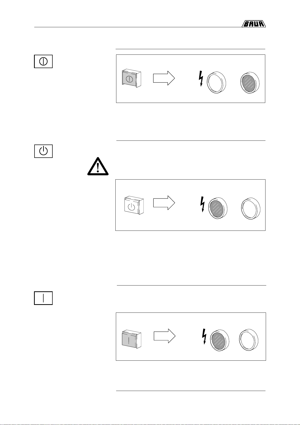
After pressing push-button switch: Signal lamps
not illuminated illuminated
Testing Set on STANDBY - Control lines of the Testing Set are connected to mains.
- Primary circuits of high voltage supply are not connected to
mains.
- Discharge device is connected to high voltage output.
Ready for switching
on for High Voltage
Power On/Off
illuminated
Preconditions:
- All persons must leave hazard area!
- Secure hazard area according to local safety rules and
regulations.
After pressing push-button switch: Signal lamps
Precondition:
- Testing Set is READY FOR SWITCHING ON
After pressing push-button switch: Signal lamps
- Primary circuits of high voltage supply are connected to mains.
- The high voltage output can be alive.
Testing Set is activated
High Voltage
Clearance
illuminated not illuminated
Continued
red green
red green
green
red
illuminated
illuminated not illuminated
- The operating condition ’READY FOR SWITCHING ON’ for High
Voltage is activated. The requirement for clearing the H.V. is met.
- Primary circuits of high voltage supply are not connected to
mains.
- Discharge unit no longer connected to high voltage output.
Testing Set is
READY FOR SWITCHING ON
1-5
1. Product Information
Important key commands, Continued
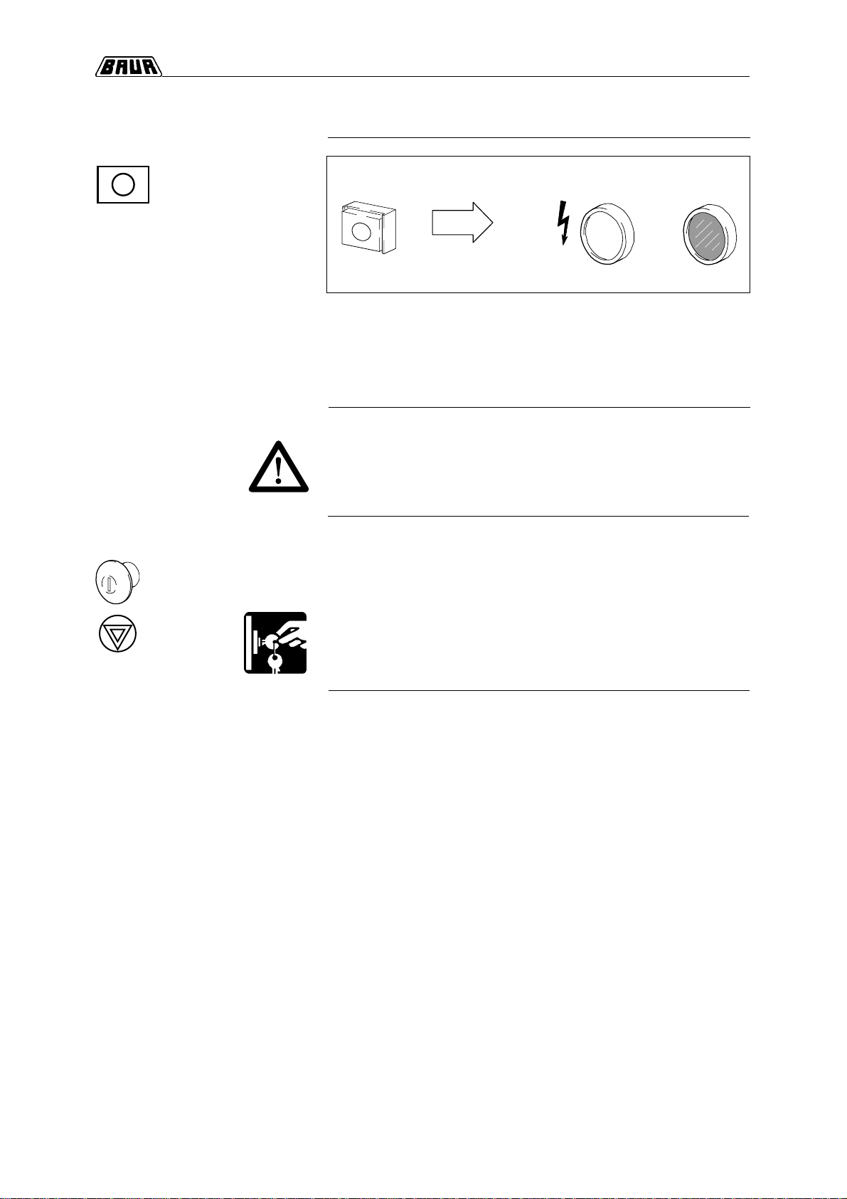
After pressing push-button switch: Signal lamps
High Voltage OFF
Testing Set on STANDBY - The mode of operation changes fromACTIVATED to STANDBY.
- Primary circuits of high voltage supply are disconnected from
mains.
- Discharge device is connected to high voltage conducting parts.
red green
illuminated
not illuminated
The Emergency-Stop pushbutton switch:
- is used for immediate shutdown in case of danger. (High
voltage will be switched off and discharge device is activated).
- is equipped with a key lock.
- Pressing the Emergency-Stop push-button switch and removal
of the key assures protection against unauthorized usage.
Emergency-Stop
push-button switch,
lockable
Use appropriate equipment:
- make sure that all parts that are not earthed (low resistance)
are no longer alive!
Before removing safety
precautions
1-6
1. Product Information
Display and Operating Elements
0
246810 12 141618
20
22
24
26
28
30
100mA
10mA
1mA100µA
10µA
1µA
F1
F2
PGK
T/min U
DC
U
max
B
0
20
4
0
6
0
8
0
1
0
0
U [kV]
I
00
0
abcd
e
fikn
o
ghml
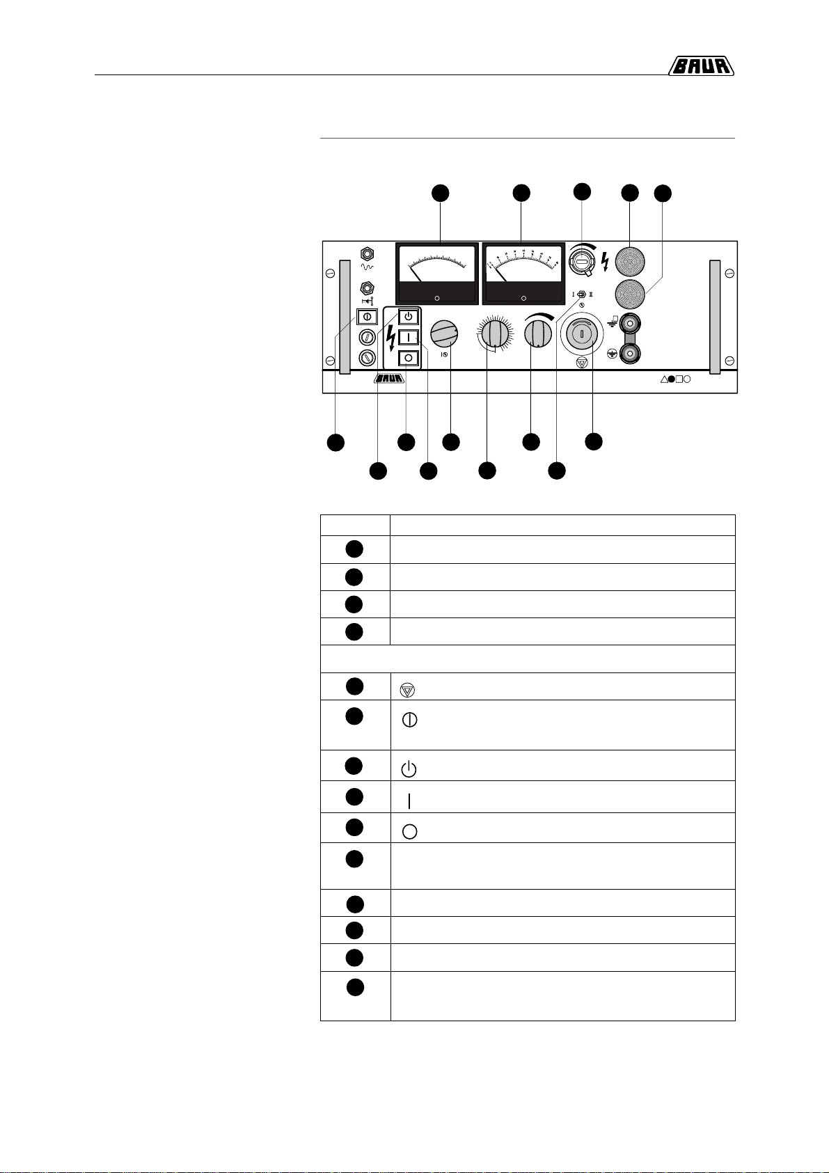
Control panel
PGK
Legend Pos. Display elements
Amperemeter for indication of output current
Voltmeter for display of output voltage in kV
Signal lamp, red
Signal lamp, green
Operating elements
Emergeny-Stop push-button switch, lockable
Power ON/OFF push-button switch
(with Power On pilot lamp)
Ready for switching on H.V. push-button switch
High voltage clearing (with pilot lamp)
High voltage OFF
Current measuring range switch
(1µA/10µA/100µA/1mA/10mA/100mA)
Voltage measuring range switch I/II
Timer (0-30 minutes)
Voltage regulating knob for setting output voltage
Potentiometer for fine adjustment (with scale 0-999);
for output voltage limitation
a
b
c
d
e
f
g
h
i
k
l
m
n
o

1-7
1. Product Information
PGK Interfaces
0
246810 12 141618
20
22
24
26
28
30
100mA
10mA
1mA100µA
10µA
1µA
F1
F2
PGK
T/min U
DC
U
max
B
0
20
4
0
6
0
8
0
1
0
0
U [kV]
I
00
0
Control panel
of PGK
p
q
s
r
t
Pos. Interfaces
Connecting socket (6.3-mm-dia.) for plotter
Connecting socket (6.3-mm-dia.) for electric gate,
EMERGENCY-STOP switch and warning lamps
Protective earth terminal
Short circuit bridge for earthing of measuring earth
terminal
B
Measuring earth terminal
p
Legend
q
r
s
t

1-8
1. Product Information
Technical Data - PGK50 and PGK80
Power supply
Rated power 230 V, 50/60 Hz Optional: 110 / 115 / 120 / 127 / 220 / 240 V
690 VA
PGK50: 1610 VA PGK80: 1380 VA
50 kV DC neg. 80 kV DC neg.
2 mA 0.8 mA
25 mA 20 mA
Installed load
Rated output voltage
Rated output current
Short circuit output current
Accuracy
Timer
Discharge device
±2,5 %
0 - 30 min
for a maximum discharge energy of 1 discharge per 15 minutes,
TU=20°C, max. 8000 Ws
Current measuring range
smallest readable current 1 µA / 10 µA / 100 µA / 1 mA / 10 mA / 100 mA
20 nA
PGK50: 0 - 10 kV PGK80: 0 - 16 kV
0 - 50 kV 0 - 80 kV
Voltage measuring range I
II
Relative humidity
Ambienttemperature not condensing
Working: 0°C ... +45°C Storage: - 20°C ... +60°C
Dimensions (WxHxD)
Weight 500 x 285 x 460 mm
25 kg
Conforms to standard Low voltage directive 73/23/EEC
EN 61010-1, VDE 0104, EMC directive 89/336/EEC with
modification 91/263/EEC, 92/31/EEC; VDE 0843 part 2, IEC 801-2
/ VDE 0843 part 4, IEC 801-4; VDE 0875 part 11, EN 55 011

1-9
1. Product Information
PGK Load Curves
PGK50 load curve
PGK80 load curve
U / kV
I / mA
U / kV
I / mA
U = f (I)
U = f (I)

1-10
1. Product Information
Notes
○○○○○○○○○○○○○○○○○○○○○○○○○○○○○○○○○○○○○○
○○○○○○○○○○○○○○○○○○○○○○○○○○○○○○○○○○○○○○
○○○○○○○○○○○○○○○○○○○○○○○○○○○○○○○○○○○○○○
○○○○○○○○○○○○○○○○○○○○○○○○○○○○○○○○○○○○○○
○○○○○○○○○○○○○○○○○○○○○○○○○○○○○○○○○○○○○○
○○○○○○○○○○○○○○○○○○○○○○○○○○○○○○○○○○○○○○
○○○○○○○○○○○○○○○○○○○○○○○○○○○○○○○○○○○○○○
○○○○○○○○○○○○○○○○○○○○○○○○○○○○○○○○○○○○○○
○○○ ○○○○○○○○○○○○○○○○○○○○○○○○○○○○○○○○○○○
○○○ ○○○○○○○○○○○○○○○○○○○○○○○○○○○○○○○○○○○
○○○ ○○○○○○○○○○○○○○○○○○○○○○○○○○○○○○○○○○○
○○○ ○○○○○○○○○○○○○○○○○○○○○○○○○○○○○○○○○○○
○○○ ○○○○○○○○○○○○○○○○○○○○○○○○○○○○○○○○○○○
○○○ ○○○○○○○○○○○○○○○○○○○○○○○○○○○○○○○○○○○
○○○ ○○○○○○○○○○○○○○○○○○○○○○○○○○○○○○○○○○○
○○○ ○○○○○○○○○○○○○○○○○○○○○○○○○○○○○○○○○○○
○○○○○○○○○○○○○○○○○○○○○○○○○○○○○○○○○○○○○○
○○○ ○○○○○○○○○○○○○○○○○○○○○○○○○○○○○○○○○○○
○○○ ○○○○○○○○○○○○○○○○○○○○○○○○○○○○○○○○○○○
○○○ ○○○○○○○○○○○○○○○○○○○○○○○○○○○○○○○○○○○
○○○ ○○○○○○○○○○○○○○○○○○○○○○○○○○○○○○○○○○○
○○○ ○○○○○○○○○○○○○○○○○○○○○○○○○○○○○○○○○○○
○○○ ○○○○○○○○○○○○○○○○○○○○○○○○○○○○○○○○○○○

2. Packing and Shipping
2-1
2. Packing and Shipping
The Testing Sets are shipped in robust cardboard cartons. If Testing
Sets are not used immediately, store in carton in dry room!
Damage during transport Complaints concerning damage should be made to us without
delay, using a standard damage claims form.
Confirmation of visible damage should immediately be obtained
from the carrier. The extent and probable cause of the damage
should be stated.
If damage is discovered during unpacking, contact the responsible
transportation company immediately. Request a written loss
assessment and make them responsible for the damage.
We also refer to the ’General Terms of Sales and Delivery’ of:
BAUR Prüf- und Messtechnik GmbH,
A-6832 Sulz /Austria
2. Packing and Shipping
2-2
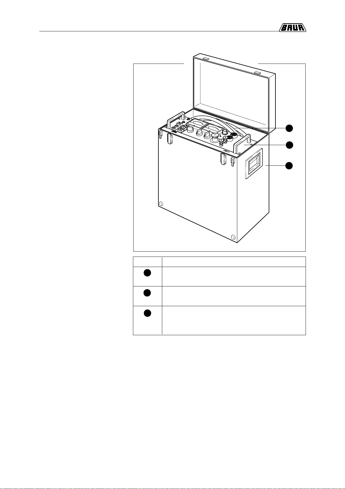
Items included
PGK50/80
1
Pos. Designation
High voltage Testing Set PGK50 or PGK80 including
test log and operating instructions
Carrying case with handles, foldable mounting legs
and cable compartment
Shielded high voltage cables with connecting clamps,
power cord, earth lead, measuring earth lead,
carrying strap
2
-
Standard items
3
1
2
3
3-1
3. Preparations for a Test
Topic Page
Connect test object 3-2
Set timer 3-4
Connect plotter 3-5
Connect EMERGENCY-STOP switch, electric gate,
signal lamps 3-6
3. Preparations for a Test
Overview
This section contains all necessary information concerning the
proper test preparation of the High Voltage Testing Sets PGK50 and
PGK80.
This section contains the following topics:

3-2
3. Preparations for a Test
Connect test object
Test configuration A and B must be
strictly adhered to! The current measuring section of the PGK has an available test
range of 10µA to 100 mA.
Test configuration A for test current ranges of 10µA to 100mA.
Test object is earthed!
Test configuration B for test current ranges of 1µA to 100mA.
Test object is isolated!
☞
Important:
The described procedure for test configuration A and B must
be strictly adhered to!
The local safety and accident prevention rules apply!
Continued
For test current ranges of 10µA to 100mA. Test object is earthed!
In test configurationAall secondary output currents will be
registered.At voltages higher than 10kV corona and insulation
currents of the PGK of with more than 100nAmay occur. These
currents will be registered during the return flow from the high
voltage source to the current measuring device.
Test configuration A
D
C
U
max
B
00
0
Protective earth Protective earth
Test object
Shielding
High voltage line from PGK
Shielding of high voltage line
of PGK
3
2
1
4
65
Step Procedure for test configuration A
Connect protective earth clamp of PGK to earth.
Connect test object to protective earth.
Connect short circuit bridge between test earth
terminal
B
and protective earth terminal .
Connect shielding of high voltage lead to protective
earth.
Connect high voltage lead to test object.
Plug in powercord of PGK.
Proceedings
1
2
3
4
5
6
High voltage connecting clamp with
transient protection resistor
This manual suits for next models
1
Table of contents
Other Baur Test Equipment manuals


Popular Test Equipment manuals by other brands


YSI
YSI Professional Plus user manual

Keysight Technologies
Keysight Technologies InfiniVision 6000L Series Service guide

Unit
Unit UT501A operating manual

Dongguan Xin Bao Instrument
Dongguan Xin Bao Instrument XB-OTS-106 Operation manual

Alcoscan
Alcoscan ACE EASY AL5500 user manual

Velleman
Velleman EDU08 Assembly manual