YSI Professional Plus User manual

USER MANUAL

CONTENTS
Warranty ..............................................................................................................i
Introduction ....................................................................................................... 1
Getting Started ................................................................................................... 1
Initial Inspection................................................................................. 1
Battery Installation ............................................................................. 1
Setup .................................................................................................... 2
Keypad ................................................................................................. 9
Main Display .....................................................................................11
Menu Layout...................................................................................... 11
Alpha/Numeric Entry.......................................................................12
System Menu ....................................................................................................13
Date/Time.........................................................................................13
GLP..................................................................................................... 14
Language............................................................................................ 18
Radix Point ........................................................................................18
Logging .............................................................................................. 18
Auto Shutoff ...................................................................................... 19
Backlight ............................................................................................19
SW Version (Software Version)....................................................... 19
Serial #................................................................................................ 19
Unit ID ............................................................................................... 20
Parameters: Setup, Display, Auto Stable, and Calibration ........................... 20
Temperature.......................................................................................20

Dissolved Oxygen (DO)................................................................... 21
Barometer ..........................................................................................31
Conductivity......................................................................................32
pH....................................................................................................... 38
ORP .................................................................................................... 42
Ammonium, Nitrate, Chloride........................................................ 45
Taking Measurements...................................................................................... 51
Dissolved Oxygen ............................................................................. 51
Conductivity ..................................................................................... 52
H/ORP .............................................................................................52
Ammonium, Nitrate, and Chloride ................................................ 52
Logging Data ..................................................................................... 52
Files and Site Lists............................................................................................ 53
File Memory ......................................................................................53
Viewing Saved Data .......................................................................... 53
Site List...............................................................................................54
Folder .................................................................................................54
Delete Data ........................................................................................54
Data Manager Desktop Software.................................................................... 55
Using the Communications Saddle................................................. 56
Manage Logged Data .......................................................................57
Real Time Studies ............................................................................. 57
Configure Instruments.....................................................................58
Care, Maintenance, and Storage ..................................................................... 58
Updating Instrument Firmware ......................................................58
General Maintenance .......................................................................58
Sensor Maintenance..........................................................................60
Sensor Storage ................................................................................... 66
Troubleshooting ...............................................................................................68
Help ...................................................................................................68
Error Messages ................................................................................. 69
Dissolved Oxygen ............................................................................. 70
Restore Default Calibration Values ............................................................... 70
Accessories / Part Numbers ............................................................................ 71
Declaration of Conformity.............................................................................. 75
Recycling........................................................................................................... 78
Contact Information........................................................................................79
Ordering and Technical Support..................................................... 79
Service Information..........................................................................79

i
WA R R A N T Y
The YSI Professional Plus Instrument (Pro Plus) is warranted for three (3) years
from date of purchase by the end user against defects in materials and workmanship,
exclusive of batteries and any damage caused by defective batteries. Pro Plus field
cables are warranted for two (2) years from date of purchase by the end user against
defects in material and workmanship (6 months for non-field rugged cables*). Pro
Plus sensors (pH, ORP, pH/ORP combo, Polarographic DO) are warranted for
one (1) year from date of purchase by the end user against defects in material and
workmanship (6 months for ammonium**, nitrate**, chloride**, and Galvanic DO).
Pro Plus systems (instrument, cables & sensors) are warranted for 90 days from
date of purchase by the end user against defects in material and workmanship when
purchased by rental agencies for rental purposes. Within the warranty period, YSI
will repair or replace, at its sole discretion, free of charge, any product that YSI
determines to be covered by this warranty.
To exercise this warranty, call your local YSI representative, or contact YSI Customer
Service in Yellow Springs, Ohio at +1 937 767-7241, 800-897-4151 or visit www.
YSI.com (Support tab) for a Product Return Form. Send the product and proof
of purchase, transportation prepaid, to the Authorized Service Center selected by
YSI. Repair or replacement will be made and the product returned, transportation
prepaid. Repaired or replaced products are warranted for the balance of the original
warranty period, or at least 90 days from date of repair or replacement.
LIMITATION OF WARRANTY
This Warranty does not apply to any YSI product damage or failure caused by:
failure to install, operate or use the product in accordance with YSI’s written1.
instructions;
abuse or misuse of the product;2.
failure to maintain the product in accordance with YSI’s written instructions or3.
standard industry procedure;
any improper repairs to the product;4.
use by you of defective or improper components or parts in servicing or5.
repairing the product;
modification of the product in any way not expressly authorized by YSI.6.
THIS WARRANTY IS IN LIEU OF ALL OTHER WARRANTIES, EXPRESSED OR
IMPLIED, INCLUDING ANY WARRANTY OF MERCHANTABILITY OR FITNESS
FOR A PARTICULAR PURPOSE. YSI’s LIABILITY UNDER THIS WARRANTY
IS LIMITED TO REPAIR OR REPLACEMENT OF THE PRODUCT, AND THIS
SHALL BE YOUR SOLE AND EXCLUSIVE REMEDY FOR ANY DEFECTIVE
PRODUCT COVERED BY THIS WARRANTY. IN NO EVENT SHALL YSI BE
LIABLE FOR ANY SPECIAL, INDIRECT, INCIDENTAL OR CONSEQUENTIAL
DAMAGES RESULTING FROM ANY DEFECTIVE PRODUCT COVERED BY
THIS WARRANTY.
THIS PAGE LEFT INTENTIONALLY BLANK

ii
1
INTRODUCTION
Thank you for purchasing the YSI Professional Plus (Pro Plus). The Pro Plus
features a waterproof (IP-67) case, backlit display and keypad, user-selectable
cable options, USB connectivity, large memory with extensive site list capabilities,
and a rugged, rubber over-molded case.
Reading the entire manual before use is recommended for an overall
understanding of the instrument’s features.
GETTING STARTED
InItIal InspectIon
Carefully unpack the instrument and accessories and inspect for damage.
Compare received parts with items on the packing list. If any parts or materials
are damaged, contact YSI Customer Service at 800-897-4151 (+1 937 767-7241)
or the authorized YSI distributor from whom the instrument was purchased.
Battery InstallatIon
The Pro Plus requires (2) alkaline C-cell batteries which are included with the
purchase of a new instrument. Battery life depends on parameters and usage.
Under normal conditions, battery life is approximately 80 hours for continuous
use at room temperature. To install or replace the batteries:
Turn the instrument over to view the battery cover on the back.1.
Unscrew the four captive battery cover screws.2.
Remove the battery cover and install the new batteries, ensuring correct3.
polarity alignment on the instrument or the removed cover. (Figure 1)
Replace the battery cover on the back of the instrument and tighten the four4.
screws. Do NOT over-tighten.
Figure 1. Pro Plus with battery cover removed. Notice
battery symbols indicating polarities.
* The warranty period for the non-field rugged cables (605107, 605177, 605108,
605178, 605109, 605179) is listed as 6 months. However, the true “working life” of
these sensors may be 3-9 months depending on storage and usage in solutions other
than clean aqueous samples.
** The warranty for the ammonium, nitrate, and chloride sensors (605104, 605105,
605106) is listed as 6 months. However, the true “working life” of these sensors may
be 3-9 months depending on storage and usage in solutions other than clean aqueous
samples.

2
3
recommended for lab use or controlled conditions where a more rugged, field
cable is not necessary. These cables include:
Cable number 605107 1-meter cable; single-junction pH sensor
Cable number 605177 4-meter cable; single-junction pH sensor
Cable number 605108 1-meter cable; single-junction ORP sensor
Cable number 605178 4-meter cable; single-junction ORP sensor
Cable number 605109 1-meter cable; single-junction pH/ORP sensors
Cable number 605179 4-meter cable; single-junction pH/ORP sensors
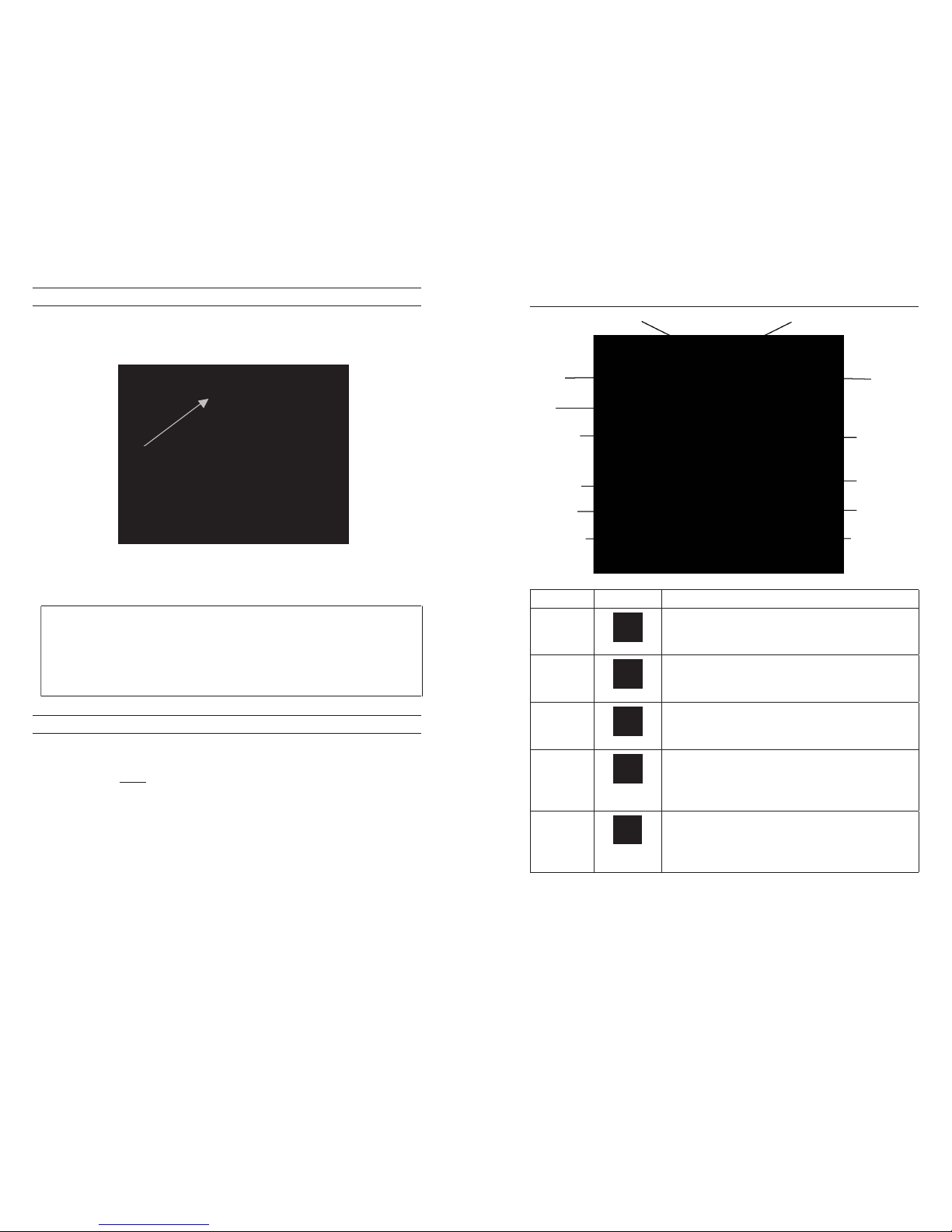
STANDARD PRO SERIES SENSOR INSTALLATION
Throughout the manual, the term “sensor” refers to the removable portion or
electrode sensing portion of the cable assembly. For example, the DO sensor or
pH sensor is the part that can be removed from a field cable and replaced with a
new sensor. The conductivity sensor is not removable from a non-Quatro cable
but still refers to the “sensing” portion and will be referred to as a sensor. This
section covers most of the sensor installations on a Professional Series cable
bulkhead including the following sensors:
2003 - Polarographic
DO (black)
1001 - pH 1003 - pH/ORP 1005 - Chloride
2002 - Galvanic
DO (gray)
1002 - ORP 1004 - Ammonium 1006 - Nitrate
See the next section of this manual for installation instructions for the Quatro
cable’s Conductivity/Temperature sensor.
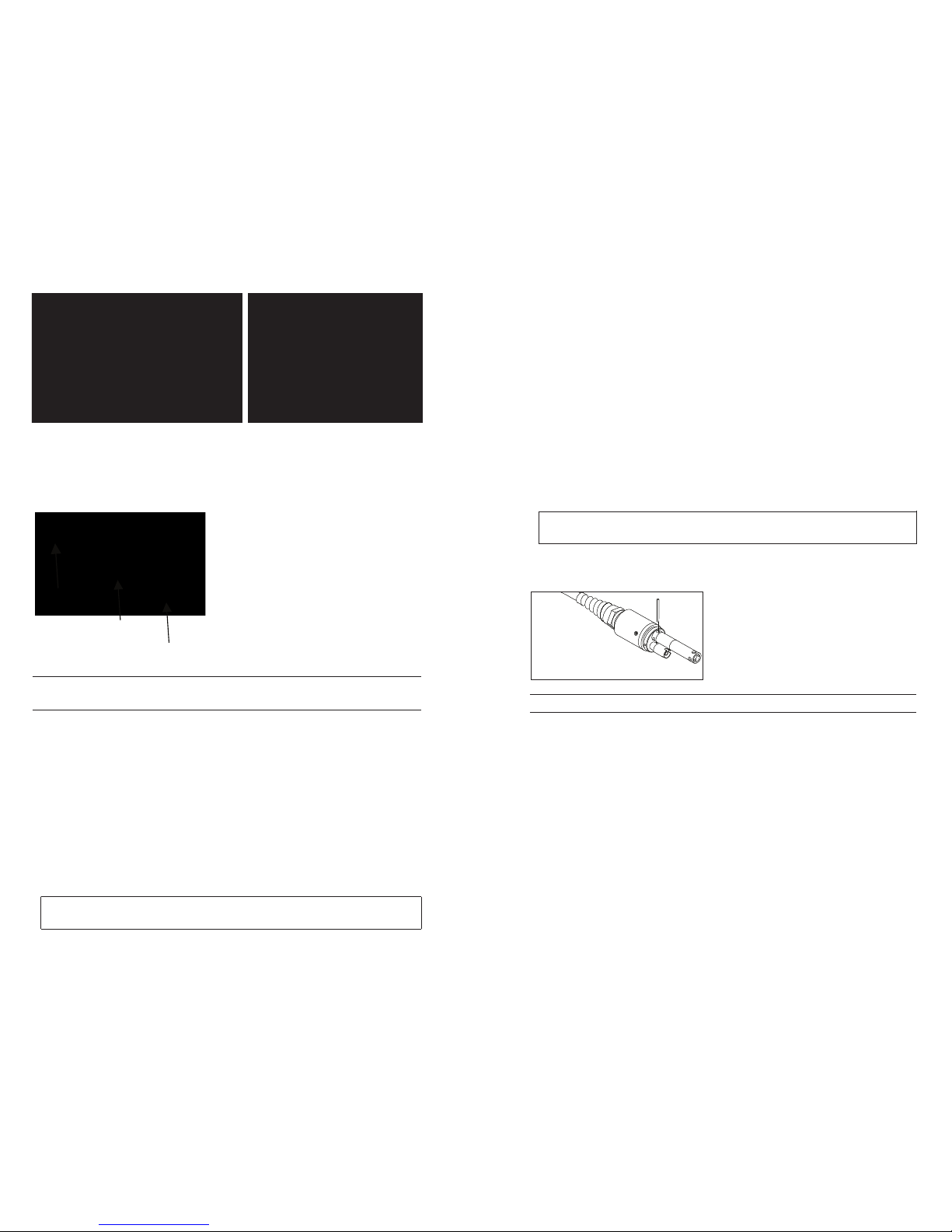
Dual sensor bulkhead ports are numbered 1
and 2, see figure to the left. Please refer to the
following tables to determine correct sensor
installation into each port of a two port cable.
Batteries must be installed in the instrument even if powering
the unit via the USB connection. This will retain the correct
date and time if the PC is turned off. If the USB power is
disconnected and there are no batteries in the instrument, the
date and time will need to be reset upon subsequent power on.
NOTE - On subsequent battery changes you will have approximately 2 minutes
to change the batteries before the clock resets. If the clock resets, the instrument
will automatically bring up the Date/Time menu the next time it is powered on
in order to update this information. This is important, especially if you intend
to log data!
setup
The Pro Plus instrument has several compatible field-rugged cable/sensor
options, each with temperature:
Cable: Available Sensors:
Cable number 60520-x DO/temp (605780 for lab BOD)
Cable number 60530-x Conductivity/temp
Cable number 60510-x ISE*/temp
Cable number 6051010-x ISE*/ISE*/temp
Cable number 6051020-x ISE*/DO/temp
Cable number 6051030-x ISE*/conductivity/temp
Cable number 6052030-x DO/conductivity/temp
Cable number 605790-x DO/conductivity/ISE*/ISE*/temp (Quatro**)
*ISE (Ion Selective Electrode) notates a port that can accept pH, ORP, Ammonium,
Nitrate, Chloride, and, in some cases, a pH/ORP combination sensor.
**Cable 605790 will be referred to as a Quatro cable throughout this manual.
All cables come in standard lengths of 1, 4, 10, 20, and 30-meters (3.28, 13,
32.8, 65.6, and 98.4-feet) with options for special order lengths up to 100-meters
(328-feet) on the 60520-x cables. Contact YSI or your local representative for
additional information.
In addition there are several cable options with built in sensors for the
measurement of pH and ORP that are not considered field-rugged (non-
replaceable sensors, less rugged single-junction sensors). These cables are
i

4
5
1010 dual cable
Port 1 Options Port 2 Options
pH pH
ORP ORP
pH or pH/ORP* pH or pH/ORP*
ammonium ammonium
chloride chloride
nitrate nitrate
none (port plug)
* If using a 6051010 cable, a sensor must be installed in port 1 for correct
operation. If you install a pH/ORP combo sensor into a 6051010 cable, ORP
will not be measured. It is not recommended to use a pH/ORP combo sensor
on a 6051010 cable.
1020 dual cable
Port 1 Options Port 2 Options
pH Polarographic DO
ORP Galvanic DO
pH or pH/ORP none (port plug)
ammonium
chloride
nitrate
none (port plug)
If using a 1020 cable, install a pH, ORP, pH/ORP, Ammonium, Nitrate or
Chloride sensor in port 1 and a DO sensor in port 2.
If using a 605103 pH/ORP combination probe on a
6051020 or 6051030 cable you can report both pH
and ORP. However, it is recommended to set ISE1 as
pH and ISE2 as ORP in the Sensor Setup menu.
The Quatro cable bulkheads are labeled
1, 2, DO, and CT, see figure to the left. All
sensors except the Conductivity/Temperature
sensor can be installed following the Standard
Pro Series Sensor Installation instructions.
Conductivity/Temperature sensor installation
is described in the next section. For ease of
installation, YSI recommends that you install
a sensor into port 1 first; followed by DO
installation, then port 2, and lastly C/T.
Quatro
Cable (pn:
605790)
Port 1
Options
Port 2
Options
DO Port
Options
CT Port Options
pH pH Polarographic
DO
5560
Conductivity/
Temperature
sensor only
ORP ORP Galvanic DO
pH or pH/
ORP*
pH or pH/
ORP*
none (port
plug)
ammonium ammonium
chloride chloride
nitrate nitrate
none (port
plug)
* If using a Quatro cable, a sensor must be installed in port 1 for correct
operation of port 2. If you install a pH/ORP combo sensor into a Quatro
cable, ORP will not be measured. It is not recommended to use a pH/ORP
combo sensor on a Quatro cable.
Before installing either dissolved oxygen sensor, the instrument
must be configured for the sensor being installed. See
the Setup - Dissolved Oxygen section of this manual for
instrument configuration instructions. Failure to do this
may result in damage not covered under warranty.
First, ensure both the sensor connector and sensor port on the cable are
clean and dry. To connect the sensor, grasp the sensor with one hand and the
sensor connection end of the cable (bulkhead) in the other. Push the sensor
into the connector on the cable until it is properly seated and only one o-ring
is visible. Failure to properly seat the probe may result in damage. Twist the
sensor clockwise to engage threads and finger tighten (Figure 2). Do not use a
tool. This connection is waterproof. Please refer to the sensor installation sheet
that is included with each sensor for detailed instructions.
i
i

6
7
Figure 2. The image on the left shows a clean, dry sensor being
aligned with the bulkhead. On the right, the sensor has been
pushed into the bulkhead and is being screwed into place.
Figure 3. The sensor(s) will install directly
in the cable bulkhead. Once installed, the
sensor guard will protect the sensor during
sampling (DO cap membrane not shown).
CONDUCTIVITY/TEMPERATURE SENSOR INSTALLATION IN A
QUATRO CABLE
As mentioned, the installation of the Conductivity/Temperature sensor (model
5560) in a Quatro cable is different from all other Pro Series sensor installations.
Follow these instructions when installing a conductivity/temperature sensor in
a Quatro cable:
Locate the C/T port and, if replacing, remove the old sensor using the1.
installation tool to loosen the stainless steel retaining nut. Once the stainless
steel retaining nut has been completely unscrewed from the bulkhead,
remove the old sensor from the bulkhead by pulling the sensor straight out
of the bulkhead.
Apply a thin coat of o-ring lubricant (supplied with the sensor) to the o-rings2.
on the connector side of the new sensor.
Visually inspect the port for moisture. If moisture is found,
it must be completely dried prior to sensor installation.
Align the connectors of the new sensor and the port. With connectors3.
aligned, push the sensor in towards the bulkhead until you feel the sensor
seat in its port. You will experience some resistance as you push the sensor
inward, this is normal
Once you feel the sensor seat into the port, gently rotate the stainless steel4.
sensor nut clockwise with your fingers, Do not use the tool.
The nut must be screwed in by hand. If the nut is difficult to turn, STOP, as5.
this may indicate cross threading. If you feel resistance or cross threading
at any point, unscrew the nut and try again until you are able to screw the
nut down completely without feeling any resistance. Damage to your cable/
sensor may occur if you force the parts together.
Once completely installed, the nut will seat flat against the bulkhead. At6.
this point, use the tool that was included with the sensor to turn the nut an
additional ¼ to ½ turn so it cannot come loose (figure 4). DO NOT over
tighten.
Do not cross thread the sensor nut. Seat nut on
face of bulkhead. Do not over tighten.
Please refer to the sensor installation sheet that is included with the conductivity/
temperature sensor for detailed instructions.
Figure 4. Installation tool used to
tighten stainless steel retaining nut of
5560 conductivity/temperature sensor.
INSTALLING PORT PLUGS IN UNUSED PORTS
As necessary, install a port plug into any port that does not have an installed
sensor. This will protect the bulkhead from water damage. Port plugs and a
tube of o-ring lubricant are included with all Quatro cables. These items can be
ordered separately if needed. To install a port plug, apply a thin coat of o-ring
lubricant to the two o-rings on the port plug. After application, there should
be a thin coat of o-ring lubricant on the o-rings. Remove any excess o-ring
lubricant from the o-ring and/or port plug with a lens cleaning tissue. Next,
insert the plug into an empty port on the bulkhead and press firmly until seated.
Then, turn the plug clockwise to engage the threads and finger-tighten until the
plug is installed completely. Do not use a tool to tighten the plug.
i
i
Sensor Guard
Sensor
Cable Bulkhead

8
9
CONNECTING THE CABLE TO AN INSTRUMENT
To connect a cable, align the keys on the cable connector to the slots on the
instrument connector. Push together firmly, then twist the outer ring until it
locks into place (figure 5). This connection is water-proof.
Figure 5. Note the keyed connector. The cable and instrument
connectors can only be mated once the keys are properly aligned.
When a sensor is not installed, the sensor and cable sensor
connectors are NOT water-proof. Do not submerge the cable
without a sensor or port plug installed in all available ports.
When the cable is disconnected, the cable’s instrument connector
and the connector on the instrument maintain an IP-67 rating.
SENSOR STORAGE
The cable assembly is supplied with a storage container, or sleeve, that installs
on to the cable. The container is used for short-term storage (less than 30 days).
Be sure to keep a small amount of moisture (tap water) in the container during
storage. This is done to maintain a 100% saturated air environment which is
ideal for short-term sensor storage (see Care, Maintenance, and Storage for more
detailed information). Do not submerge the sensors in an aqueous solution.
The intent is to create a humid air storage environment.
Keypad
Number Key Description
1System
Opens System Menu from any screen.
Use to adjust system settings.
2Sensor
Opens Sensor Menu from any screen.
Use to enable sensors and display units.
3Calibrate
Opens Calibrate Menu from any screen.
Use to calibrate all parameters except temperature.
4File
Opens File Menu from any screen.
Use to view data and GLP files, set up
site and folder lists, and delete data.
5Backlight
Press to turn the instrument backlight on and
off and to adjust the display contrast when
pressed with the left or right arrow key.
i
1
23
4
5
6
7
8
9
10
11
12
13

10
11
Number Key Description
6Right Arrow
Use to navigate right in alpha/numeric entry
screens. Can be pressed simultaneously with
Backlight key to increase display contrast.
7Down Arrow
Use to navigate through menus and to navigate
down in alpha/numeric entry screens.
8Power
Press to tur n the instr um ent on.
Press and hold for 3 seconds to turn off.
9Help
Press to receive hints & tips during operation.
10 Enter
Press to confirm selections, including
alpha/numeric key selections.
11 Left Arrow
Use to navigate left in alpha/numeric entry screens.
Press to return to previous menu in all
screens except alpha/numeric entry.
Can be pressed simultaneously with Backlight
key to decrease display contrast.
12 Exit/Escape
Exits back to Run Screen.
When in alpha/numeric entry screen,
escapes to previous menu.
13 Up Arrow
Use to navigate through menus and to navigate
up in alpha/numeric entry screens.
MaIn dIsplay
Press the Power key to turn the instrument on. The instrument will briefly
display the splash screen with the YSI logo then go directly to the main run
screen. The first time the instrument is powered up or if the instrument
has had a battery change (with batteries removed for more than 2 minutes),
you will need to set the date and time. Follow the instructions under
System Menu | Date/Time.
The display at the left shows the run mode (main
display) with temperature in °C, barometer
in mmHg, DO in % and mg/L, and pH as the
reported parameters. The date, time and battery
level are indicated at the bottom of the screen.
The logging preference of Log One Sample at a
time is indicated at the top of the screen.
This screen also shows the message line towards
the bottom of the display above the date and
time. In this case, it doesn’t show a message
but messages will appear frequently to indicate
calibration steps, set date and time, etc.
A USB symbol will show up on the
bottom of the display when connected to a PC
through USB with the communications saddle. The instrument will display full
battery power when it is receiving power through the USB connection.
Contrast – the contrast adjustment can be accomplished by pressing
the backlight key and the left or right arrow key at the same time.
Menu layout
Press Esc at anytime in the menus to escape back to the Run screen. The
left arrow can be used to go back to the previous menu in all screens except
alpha/numeric entry screens. You must use Esc to get out of the alpha/numeric
screens if you want to exit before finishing or without saving changes. Functions
that are enabled appear as a circle with a dot or a box with a check mark Q.
Disabled functions appear as a circle only or an empty P.
i

12
13
alpha/nuMerIc entry
The numeric screens will display numbers only (shown on the left). Alpha/
numeric screens will display numbers across the top and letters along the
bottom rows (shown on the right). Letters appear as a common keyboard
arrangement.
When an alpha or numeric character is required, the screen will show the alpha/
numeric entry screen. To select a character, highlight it by using the arrow keys
to move the highlight box over the desired selection. Then, press Enter on the
keypad to confirm the selection. After confirming the selection, it will appear
in the line at the top of the display.
For capital letters or lower case entry, highlight “SHIFT” and press Enter on the
keypad to change the characters from upper to lower case.
To delete the entire line of the current entry, highlight )and press Enter on the
keypad. The !symbol functions as a backspace key in the alpha/numeric entry
screens by deleting one character at a time. Use the “SPACE” function to add a
space between characters.
When you have finished entering the correct information (16 character max),
highlight <<<ENTER>>> at the bottom of the screen and press Enter on
the keypad to confirm.
The key cannot be used to escape to the previous menu from
an alpha/numeric entry screen. Instead, use the key to go
back to the previous menu when in alpha/numeric entry screens.
SYSTEM MENU
Press System to access any of the following
menu items.
The System menu will allow you to access the
setup options of the instrument including; Date/
Time, GLP, Language, Radix Point, Logging,
Auto-Shutoff, Backlight, SW (Software)
Versi on, Serial #, and Unit ID. Any item with
[brackets] shows the current setting inside the
brackets. For instance, in the example at the
left, Radix Point is currently set to [Decimal].
The brackets will also give a quick visual clue as
to what items can be changed.
date/tIMe
Highlight Date/Time from the System menu.
Press enter to select.
Date Format – Highlight and press enter to
open a sub menu for selecting the preferred
date format: YY/MM/DD, MM/DD/YY,
DD/MM/YY, or YY/DD/MM.
Date – Highlight and press enter to use the
numeric entry screen to set the correct date.
Time Format – Highlight and press enter to
open a submenu to select the preferred time
format from 12-hour or 24-hour.
Time – Highlight and press enter to use the
numeric entry screen to set the correct time.
The date and time will need to be reset if a battery
change takes longer than 2 minutes. When this occurs,
the Date/Time menu will automatically appear upon
power up and require you to set the date and time.
i
i

14
15
Glp
The GLP or ‘Good Laboratory Practice’ file saves detailed information
about calibrations. It also includes diagnostic information about the sensors.
Calibrations are logged into a file, the GLP, for later review as needed. A single
GLP file is utilized to store all calibration records and is capable of storing 500
records. Once the GLP file is full, the instrument will begin to overwrite the
oldest record with each new calibration record.
In order to keep all of your GLP records, periodically download
the GLP to Data Manager and export it to another program.
Otherwise, the unit will overwrite the oldest record once
the memory is full. Also, since Data Manager saves GLP
files under the Unit ID, you must periodically export and
rename the GLP file on your PC or it will be overwritten
each time you upload the GLP file from the instrument.
Several calibration parameters are saved for each calibration record including
optional ones that can be enabled by the user. Standard parameters include
date/time stamp, calibration method, and sensor information. Optional, user
selectable parameters include User ID, Probe ID, and User Fields 1 and 2.
The sensor specific information that is saved with each calibration point is
different for each sensor. The sensor specific values saved are:
Conductivity
Method (Spec Cond, Cond, Salinity)
Cal Value (value of calibration solution)
Sensor Value (Cell Constant)
Temperature Reference (User selected in Sensor Setup menu)
Temperature Compensation Coefficient %/°C (User selected in Sensor Setup
menu)
TDS Constant (User selected in Sensor Setup menu)
Temperature
Cal Cell Constant
Calibrate Status
DO
Method (%, mg/L)
Cal Value
Sensor Value (Sensor Current)
Sensor Type (Polarographic/Galvanic)
Membrane Type (Teflon Black, PE Yellow, PE Blue)
Salinity Mode (user entered value if in Manual Salinity Mode)
Temperature
Barometer
Calibrate Status
pH (up to 6 calibration points)
Buffer Value
Sensor Value (mV)
Temperature
Slope (mV/pH)
Slope (% of ideal)
Calibrate Status
ORP
Cal Solution Value
Sensor Value
Temperature
Calibrate Status
Ammonium
Buffer Value
Sensor Value (mV)
Temperature
Calibrate Status
Chloride
Buffer Value
Sensor Value (mV)
Temperature
Calibrate Status
Nitrate
Buffer Value
Sensor Value (mV)
Temperature
Calibrate Status
i

16
17
An example of a GLP record
(Operation performed is single point % DO Calibration)
*** Calibrate – DO% ***
Date 02/03/09 MM/DD/YY
Time 12:14:57PM 12-hour
User ID: Tech 1
Probe ID 08D
Method DO Air Calibrate
Cal Value: 100.00%
Sensor Value: 5.175155uA
Sensor Type Polarographic
Membrane Type 1.25 PE Yellow
Salinity Mode 5.175165 Auto
Temperature 23.9 °C
Barometer 731.4 mmHg
Calibrate Status Calibrated
GLP SETTINGS
In the System menu, highlight GLP and press
enter to view and modify the GLP settings.
Highlight Options and press enter to access
User ID, Probe ID, User Defined Fields, and
Re-Cal Prompt.
User ID may be used to identify the person
calibrating the instrument. Highlight User ID
and press enter to select, edit, or delete a User
ID from a list of previously entered IDs. Or,
highlight Add New and press enter to create
a new User ID using the alpha/numeric entry
screen. The User ID may also be changed in
the Calibration menu during the calibration
process. The selected User ID will be stored in
the GLP file with each calibration record. A
User ID could be a person’s initials or badge
number. The character limit is 16 characters.
Probe ID is stored with the calibration record
and may be used to distinguish one cable/probe
assembly from another, typically by serial number. Highlight Include Probe ID
and press enter to turn this function on (Q) and off (P). Highlight Probe ID
and press enter to add, view, edit, delete, or select a Probe ID. The Probe ID
may also be changed in the Calibration menu during the calibration process.
The character limit is 16 characters.
User Fields 1 and 2 are stored with the calibration record and may be used
to enter other parameters pertinent to the user, such as weather conditions,
elevation, etc. Highlight Include User Field 1 or Include User Field 2 and press
enter to turn this function on and off. Highlight User Field 1 or User Field 2
and press enter to add, delete, view, edit, or select a User Field. The character
limit is 16 characters. When enabled, a prompt for selecting a User Defined
Field will appear during the calibration process.
Re-Cal Prompt may be used to remind the
user to perform a calibration. To set a time
interval, highlight the parameter you wish to
be reminded about and press enter to access the
numeric entry screen. Enter a value in days and
press enter to confirm the reminder time. To
turn off the Re-cal prompt, set the reminder to
zero (0) days (this is the default).
The Security section of the GLP menu is a password protected area. This area
includes options to set a new password and to lock access to the calibration
menu. When first viewing the security menu, you will be required to enter a
password. Use the “shift” on the alpha/numeric screen to switch to lower case if
necessary and enter “ysi123”. This is the default password.
Protect Cal can be enabled (Q) or disabled (P). When enabled, the user must
know and enter the instrument’s password to enter the calibration menu option.
Highlight Protect Cal and press enter to enable or disable this feature.
Set Password allows a user to set the security password. Highlight Set Password,
press enter, and use the alpha/numeric entry screen to set the new password.
The password can have up to 16 characters.
Contact YSI Technical Support at environmental@ysi.com or +1 937 767-7241 if
you forget or misplace your password.
Once a password is set, and the GLP security screen
exited, a password must be entered to make changes
under GLP security. Keep passwords in a safe place.
i

18
19
lanGuaGe
The Pro Plus can be configured to display all
text in English, Spanish, French, German,
Portuguese, Italian, Norwegian, Simplified
Chinese, Traditional Chinese, or Japanese. From
the factory, the instrument includes English,
Spanish, and French language options. The
other language options can be downloaded from
www.ysi.com/support.
Once the appropriate language file is in the
instrument, press System , highlight
Language, and press enter. Highlight the desired
language and press enter to confirm.
radIx poInt
Radix Point allows the user the option to
choose between a comma or a decimal in
numeric displays. For example, 1.00 becomes
1,00 when Use Comma is selected. Highlight
Use Decimal or Use Comma and press enter to
make your selection.
loGGInG
From the System menu, highlight Logging
and press enter to view or change the logging
options. Logging options include Use Site
List, Use Folder List, Continuous Mode, and
Interval.
Use Site List and Use Folder List are optional
ways of filing or ‘tagging’ your logged data
points. If these settings are enabled, you will be
prompted to select a Site and/or Folder to ‘tag’ to the logged data point. See the
File and Site Lists section of this manual for information on creating Site and
Folder Lists.
Check the box for Continuous Mode if you want to log samples continuously
at a specific time interval. To set the length of time between logged samples,
highlight Interval and press enter. Enter the interval as HH:MM:SS. This
interval will display at the top of the screen when you select the Start Logging
option in run mode.
To log one sample at a time, uncheck Continuous Mode. When Continuous
Mode is unchecked, Log One Sample will appear at the top of the run screen.
auto shutoff
Auto Shutoff powers the instrument off after a user specified time period.
Highlight Auto Shutoff and press enter. Using the alpha/numeric entry screen,
enter a value between 0 and 360 minutes. To disable auto shutoff, set the value
to 0 (zero).
BacKlIGht
Backlight can be set to Automatic or Manual.
Automatic turns the backlight on when you
turn the instrument on and when you press any
key. Manual allows you to turn the backlight
on or off with the backlight key . When
in Automatic mode, the instrument will turn
the backlight off 60 seconds after the last key
press. The instrument will “reset” the 60 second
time period every time a key is pressed. The
lighted keypad will turn off after approximately
20 seconds.
sW VersIon (softWare VersIon)
SW Version shows the instrument’s software version. The instrument’s software
can be updated via www.ysi.com/support. There you will find the new software
files and instructions on how to update the instrument. There is no need to send
the instrument back to the factory for upgrades.
serIal #
Serial # shows the instrument’s serial number and allows you to match it with
the number engraved on the back of the instrument’s case.

20
21
unIt Id
Unit ID is used to identify instruments in the Data Manager software program
that was included with your instrument. It is also used to identify GLP files, Site
Lists, Configuration files, and Data files transferred from the instrument to the
PC. The default Unit ID is the instrument’s serial number. To modify the Unit
ID, highlight Unit ID, press enter and then use the alpha/numeric entry screen.
The character limit is 16 characters.
PA R A M E T E R S : S E T U P, D I S P L A Y,
AUTO STABLE, AND CALIBRATION
The following section is separated by parameter and will discuss sensor setup,
display options, auto stable features, and calibration procedures for each
parameter. The sections are separated by parameter due to the versatility of the
Pro Plus. You may focus solely on the parameters of your choice.
For the highest accuracy, calibrate or verify each sensor regularly. For your
convenience, YSI offers 5580 Confidence Solution® which allows you to check
the accuracy of pH, conductivity, and ORP readings to help determine if a sensor
calibration is necessary.
If you receive an error message during a calibration that indicates questionable
results, you have the option to either accept or decline the calibration. YSI
recommends that you decline a questionable calibration since accepting it may
result in erroneous data. After declining a questionable calibration, ensure the
sensor is clean, the calibration solution is good, the calibration vessel is clean,
and that you are entering the correct calibration value if entering manually.
Then, try to recalibrate the sensor. If you continue to have problems, see the
Troubleshooting section of this manual.
teMperature
All probe/cable assemblies, except the Quatro,
have a built-in temperature sensor. The Quatro
cable ships with a Conductivity/Temperature
sensor that must be installed on the cable.
Temperature calibration is not required nor is
it available.
To set the units, press Sensor , highlight
Display and press enter. Highlight Temperature
and press enter. Highlight the desired
temperature units of °F,°C, or Kand press enter to confirm the selection. Only
one temperature unit may be displayed at a time. You may also choose not to
display temperature. If you choose not to display temperature, other parameters
that require a temperature reading will still be temperature compensated.
dIssolVed oxyGen (do)
DO sensors can be used on 60520-X, 6051020-X, 6052030-X, and Quatro
cables.
PREPARING THE DO SENSOR FOR THE FIRST TIME
The dissolved oxygen sensor is shipped with a dry, protective red cap that will
need to be removed before using. It is very important to put a new membrane
with electrolyte solution on the sensor after removing the red cap.
Prepare the membrane solution according to the instructions on the bottle. After
mixing, allow the solution to sit for 1 hour. This will help prevent air bubbles
from later developing under the membrane. Ensure you are using the correct
electrolyte solution for the correct sensor. Galvanic sensors utilize electrolyte
with a light blue label and Polarographic sensors utilize electrolyte with a white
label. The dissolved oxygen sensor is supplied with cap membranes specific
to the sensor type ordered (Polarographic or Galvanic). 5912, 5913, and 5914
membrane kits are for Galvanic sensors and the 5906, 5908, and 5909 membrane
kits are for Polarographic sensors. See the Setup - Dissolved Oxygen section of
this manual for more information on the different types of membranes available
from YSI.
Remove the red cap by pulling it straight off the sensor tip. Discard or save for
later use during long term storage. Thoroughly rinse the sensor tip with distilled
or deionized water. Fill the cap membrane 3⁄4 full of electrolyte solution, then
tap the cap with a finger to release any trapped air. Be careful not to touch
the membrane portion of the cap. Thread the membrane cap onto the sensor,
moderately tight. Do not use a tool. It’s typical for some of the electrolyte
solution to spill over. For detailed instructions on changing a membrane cap,
see the Care, Maintenance, and Storage section of this manual.

22
23
SETUP DISSOLVED OXYGEN
Press Sensor , highlight Setup and press enter. Next, highlight DO and press
enter.
Enabled allows you to enable or disable the
Dissolved Oxygen function. Highlight Enabled
and press enter to activate(Q) or deactivate(P)
dissolved oxygen. Disable dissolved oxygen
if you do not have a dissolved oxygen sensor
connected to the instrument.
If a sensor is Enabled that isn’t connected to the
instrument, the display will show an unstable, false
reading, ?????, or ----- next to the units.
Sensor Type sets the type of oxygen sensor being used: either Polarographic
(black) or Galvanic (grey). Highlight Sensor Type and press enter. Highlight the
correct sensor type installed on the cable and press enter to confirm.
If using a ProBOD sensor/cable assembly, the sensor type should be set to
polarographic.
The Pro Plus has two compatible sensors for use with a field cable:
Polarographic – This sensor has a black sensor body and is engraved with the
model number 2003.
Galvanic – This sensor has a grey sensor body and is engraved with the model
number 2002.
In terms of physical configuration, membrane material, and general performance,
YSI Professional Series Galvanic dissolved oxygen sensors are exactly like the
Professional Series Polarographic sensors. The advantage of using Galvanic
sensors is convenience. Galvanic sensors provide for an instant-on sensor without
the need for warm-up time but this affects the life of the sensor. Polarographic
sensors last longer and have a longer warranty but require a 5-15 minute warm-
up time before use or calibration.
IMPORTANT – The instrument default setting is Galvanic.
Please change the Sensor Type to match the correct sensor. If
you observe readings very close to 0 or extremely high readings
(i.e. 600%), your Sensor Type setting (Polarographic or
Galvanic) may be set incorrectly and you should immediately
ensure it matches the sensor installed on your cable.
Membrane sets the type of membrane used on the dissolved oxygen sensor.
Highlight Membrane and press enter. Highlight the correct membrane type
installed on the sensor and press enter to confirm. The DO sensor is supplied
with membranes specific to the sensor type ordered and are color coded as
described in the following tables.
Galvanic membrane kits:
Item Color Material Description
5912 Black 1 mil Teflon® Traditional membrane material
5913 Ye l l o w 1.25 mil polyethylene Improved response time and less
flow dependence than Teflon®
Ships standard with the sensor.
5914 Blue 2 mil polyethylene Less flow dependence than 1.25 mil
but somewhat slower response
Polarographic membrane kits:
Item Color Material Description
5906 Black 1 mil Teflon® Traditional membrane material
5908 Ye l l o w 1.25 mil polyethylene Improved response time and less
flow dependence than Teflon®
Ships standard with the sensor.
5909 Blue 2 mil polyethylene Less flow dependence than 1.25 mil
but somewhat slower response
Selecting a Dissolved Oxygen Membrane:
Membrane Type Flow Dependence After 4 Minutes
Typical Response
Time - 95%
5912, 5906 - Black 60% 18 seconds
5913, 5908 - Yellow 25% 8 seconds
5914, 5909 - Blue 18% 17 seconds
u
i

24
25
Local DO allows for localized DO% measurements. This sets the calibration
value to 100% regardless of the altitude or barometric pressure. Highlight Local
DO and press enter to enable (Q) or disable (P) this function. Local DO is
a method for the Pro Plus to factor in the barometric pressure on each DO
measurement. In essence, if the barometric pressure changes you wouldn’t notice
the difference in the DO% readings in air-saturated water or water-saturated air.
Local DO is ideal for EU compliance. When Local DO is enabled, an L will
appear next to DO% on the run screen. DO mg/L readings are unaffected by the
selection of DO Local.
LDS (Last Digit Suppression) rounds the DO value to the nearest tenth; i.e.
8.27 mg/L becomes 8.3 mg/L. Highlight LDS and press enter to enable (Q) or
disable (P) this function.
DISPLAY DISSOLVED OXYGEN
Press Sensor , highlight Display and press enter. Highlight DO and press
enter. All DO units can be displayed simultaneously. Highlight the unit(s)
and press enter to activate (Q) or deactivate (P) units from the run screen.
Note - You will not be able to display dissolved oxygen unless it is Enabled in the
Sensor Setup menu first, see previous section.
DO % will show DO readings in a percent scale
from 0 to 500%.
DO mg/L will show DO readings in milligrams
per liter (equivalent to ppm) on a scale from 0
to 50 mg/L.
DO ppm will show DO readings in parts per million (equivalent to mg/L) on a
scale from 0 to 50 ppm.
AUTO STABLE DISSOLVED OXYGEN
Auto Stable indicates when a reading is stable.When Auto Stable is enabled, AS
will blink next to the parameter until it is stable. Once the parameter is stable,
AS will stop blinking.
To enable Auto Stable, press Sensor ,
highlight Auto Stable and press enter. Highlight
DO and press enter.
Highlight Enabled and/or Audio Enabled
(instrument will beep when the stability
is achieved) and press enter to confirm. The Auto Stable Sensitivity can be
decreased or increased. Highlight Sensitivity and use the left and right arrow
keys to slide the bar. The more sensitive you make it (larger black bar) the
harder it is to achieve stability in a changing environment.
The Auto Stable system works by examining the previous 5 readings, computing
the percent change in the data and comparing that change against a % threshold
value. The % threshold value is determined by the Sensitivity bar setting. The
following chart can be used as a guide when setting the Sensitivity bar.
Sensitivity selected by User % Data Variance Threshold
100 - Most Sensitive, Sensitivity
bar is set to the far right
0.05%
75 0.62525%
50 1.275%
25 1.8875%
0 - Least Sensitive, Sensitivity
bar is set to the far left
2.5%
Example:
The instrument obtained the following data:
Reading #1 95.5 DO%
Reading #2 95.7 DO%
Reading #3 95.8 DO%
Reading #4 96.1 DO%
Reading #5 95.3 DO%
The instrument is programmed to determine the minimum and maximum
data value over the previous 5 samples, and to compute the percent difference
between those values. In this example, that gives a percent change of:
% Change = 100 * ((96.1 – 95.3 ) / 95.3)
% Change = 0.83%
In this example, if the Sensitivity bar is set to the far right, the Auto Stable
requirement would not be met and AS would continue to blink. However,
if the sensitivity bar is set to the median threshold (1.275%), the Auto Stable
requirement would be met and AS would display steadily on the display.
Within the Auto Stable menu, you can also choose to Hold All Readings for as
many parameters as you set for Auto Stable. For instance, if DO and pH have

26
27
Auto Stable and Hold All Readings enabled,
then the display will hold the readings once DO
and pH have both reached their Auto Stable
settings. You must press the Esc key to “release”
the held display in order to take subsequent
readings Hold All Readings must be reactivated
after each use!
SALINITY CORRECTION
Thelast featureintheSensormenuis the Salinity
correction value which is used to calculate the
dissolved oxygen mg/L and ammonia readings
when a conductivity sensor is not in use. Press
Sensor , highlight Salinity, and press enter.
Then, use the numeric entry screen to enter the
Salinity value of the water you will be testing
from 0 to 70 ppt.
If using a cable with a conductivity sensor, the salinity
measured by the conductivity sensor will be used in the DO and
ammonia mg/L calculations and ‘As Measured’ will be displayed next to Salinity
in the Sensor menu.
As the salinity of water increases, its ability to dissolve oxygen decreases. For
example, fully oxygenated 20 °C water at sea level with zero salinity will hold
9.092 mg/L of dissolved oxygen. If that same sample had a salinity value of 9
ppt, then it would hold 8.621 mg/L of dissolved oxygen. Therefore, to obtain
accurate mg/L readings, it is important to know the salinity of the water you
will be testing and to input that value into the instrument. The salinity of fresh
water is typically 0-0.5 ppt and seawater is typically 35 ppt. You will also have
the opportunity to enter or modify the Salinity correction value during DO
calibration.
CALIBRATION DISSOLVED OXYGEN
The Pro Plus offers several options for calibrating dissolved oxygen: DO% in
water saturated air, DO mg/L and DO ppm in a solution of known dissolved
oxygen determined by a Winkler Titration, and a Zero point. If performing a
zero point calibration, you must also perform a %, mg/L, or ppm calibration
following the zero calibration. For both ease of use and accuracy, YSI recommends
performing the following 1-point DO % water saturated air calibration:
It is not necessary to calibrate in both % and mg/L or ppm.
Calibrating in % will simultaneously calibrate
mg/L and ppm and vice versa.
Calibrating DO % in Water Saturated Air:
1-Point Calibration
The supplied sensor storage container (a grey sleeve for a single port cable or a
screw on plastic cup for the dual-port and Quatro cables) can be used for DO
calibration purposes.
Moisten the sponge in the storage sleeve or plastic cup with a small amount of
clean water. The sponge should be clean since bacterial growth may consume
oxygen and interfere with the calibration. If using the cup and you no longer
have the sponge, place a small amount of clean water (1/8 inch) in the plastic
storage cup instead.
Make sure there are no water droplets on the DO membrane or temperature
sensor. Then install the storage sleeve or cup over the sensors. The storage
sleeve ensures venting to the atmosphere. If using the cup, screw it on the cable
and then disengage one or two threads to ensure atmospheric venting. Make
sure the DO and temperature sensors are not immersed in water. Turn the
instrument on and wait approximately 5 to 15 minutes for the storage container
to become completely saturated and to allow the sensors to stabilize.
Press Cal . Highlight Probe ID or User ID
if you wish to add, select, edit, or delete an ID.
Probe ID must be enabled in the System GLP
menu to appear in the Calibrate menu. User
ID will appear automatically. Select ‘None’
if you do not want a User ID stored with the
calibration. When enabled, these IDs are stored
with each calibration record in the GLP file.
i

28
29
After selecting your User ID and/or Probe ID if appropriate, highlight DO and
press enter.
Highlight DO % and press enter to confirm.
The instrument will use the internal barometer
during calibration and will display this value
in brackets at the top of the display. Highlight
Barometer and press enter to adjust it if needed.
If the barometer reading is incorrect, it is
recommended that you calibrate the barometer.
Note - the barometer should be reading “true”
barometric pressure (see Barometer section
for more information on “true” barometric
pressure). If the value is acceptable, there is
no need to change it or perform a barometer
calibration.
The Salinity value displayed near the top of the
screen is either the salinity correction value
entered in the Sensor menu or the Salinity
value as measured by the conductivity sensor
in use and enabled. If you are not using a
conductivity sensor, the Salinity correction
value should be the salinity of the water you
will be testing. Highlight Salinity and press
enter to modify this setting if necessary. See the
Salinity Correction section of this manual for
more information.
Wait for the temperature and DO% values under “Actual Readings” to stabilize,
then highlight Accept Calibration and press enter to calibrate. Or, press Esc
to cancel the calibration. If User Field 1 or 2 are enabled in the GLP menu, you
will be prompted to select these inputs and then press Cal to complete the
calibration. The message line at the bottom of the screen will display “Calibrating
Channel...” and then “Saving Configuration...”.
Calibrating DO% in Water Saturated Air:
2-Point Calibration with Zero Solution
Place the sensor in a solution of zero DO.
A zero DO solution can be made by dissolving approximately 8 - 10 grams of
sodium sulfite (Na2SO3) into 500 mL tap water or DI water. Mix the solution
thoroughly. It may take the solution 60 minutes to be oxygen-free.
Press Cal . Highlight Probe ID or User ID if you wish to add, select, edit, or
delete an ID. Probe ID must be enabled in the System GLP menu to appear in
the Calibrate menu. When enabled, these IDs are stored with each calibration
record in the GLP file.
After selecting the Probe ID and/or User ID if appropriate, highlight DO and
press enter. Highlight Zero and press enter. Wait for the temperature and
DO% values under “Actual Readings” to stabilize, then press enter to Accept
Calibration. If User Field 1 or 2 are enabled, you will be prompted to select the
fields and then press Cal to complete the calibration. The screen will then
prompt for a follow-up second point calibration.
Highlight DO% and press enter to continue with the next calibration point.
Rinse the sensor of any zero oxygen solution using clean water. Then follow the
steps under Calibrating DO % in Water Saturated Air to complete the second
point.
Calibrating in mg/L or ppm as a Titration:
1-Point Calibration
Place the sensor into an adequately stirred sample that has been titrated to
determine the dissolved oxygen concentration. Allow the sensor to stabilize.
Press Cal . Highlight Probe ID or User ID if you wish to add, select, edit, or
delete an ID. Probe ID must be enabled in the System GLP menu to appear in
the Calibrate menu. When enabled, these IDs are stored with each calibration
record in the GLP file.
After selecting the Probe ID and/or User ID if appropriate, highlight DO and
press enter. Highlight DO mg/L or ppm and press enter.

30
31
Highlight Calibration value and press enter to
manually input the sample’s dissolved oxygen
value. Highlight Accept Calibration and press
enter once the temperature and Dissolved
Oxygen readings stabilize. Or, press Esc to
cancel the calibration. If User Field 1 or 2 are
enabled in the GLP menu, you will be prompted
to select the fields after selecting Accept
Calibration. After making your selection,
press Cal to complete the calibration. After
completing the calibration, the message line
will display “Calibrating Channel...” and then
“Saving Configuration...”.
Calibrating in mg/L or ppm as a Titration:
2-Point Calibration with Zero Solution
Place the sensor in a solution of zero DO.
A zero DO solution can be made by dissolving approximately 8 - 10 grams of
sodium sulfite (Na2SO3) into 500 mL tap water. Mix the solution thoroughly. It
may take the solution 60 minutes to be oxygen-free.
Press Cal . Highlight Probe ID or User ID if you wish to add, select, edit, or
delete an ID. Probe ID must be enabled in the System GLP menu to appear in
the Calibrate menu. When enabled, these IDs are stored with each calibration
record in the GLP file.
After selecting the Probe ID and/or User ID if appropriate, highlight DO and
press enter. Highlight Zero and press enter. Wait for the temperature and
DO% values under “Actual Readings” to stabilize, then press enter to Accept
Calibration. If User Field 1 or 2 are enabled, you will be prompted to select the
fields and then Press Cal to complete the calibration. The screen will then
prompt for a follow-up second point calibration.
Highlight the desired calibration units (mg/L or ppm) and press enter
to continue with the next point. Rinse the sensor of any zero oxygen
solution using clean water. To complete the second calibration point,
follow the steps under Calibrating in mg/L or ppm as a Titration:
1-Point Calibration.
BaroMeter
All Professional Plus instruments contain an internal barometer.
DISPLAY BAROMETER
Press Sensor , highlight Display and press enter. Highlight Barometer and
press enter. The measurement unit options are: mmHg, inHg, mBar, PSI, kPa,
or Atm. Only one unit can be displayed at a time. Select None if you do not
want to display a barometric pressure reading.
Whether or not you choose to display the barometer reading, the barometric
pressure will still be used for calibrating DO% and for compensating for pressure
changes if Local DO is enabled.
CALIBRATION BAROMETER
The barometer in the instrument is calibrated
at the factory. If the barometer requires
calibration, press Cal . Highlight Probe ID
or User ID if you wish to add, select, edit, or
delete an ID. Probe ID must be enabled in the
System GLP menu to appear in the Calibrate
menu. When enabled, these IDs are stored with
each calibration record in the GLP file.
After selecting the Probe ID and/or User ID
if appropriate, highlight Barometer and press
enter.
Highlight the desired unit and press enter.
Other manuals for Professional Plus
3
Table of contents
Other YSI Test Equipment manuals