9
4.0 Installation
4.3 Installation - Horizontal Direct Rear Flue
7210434
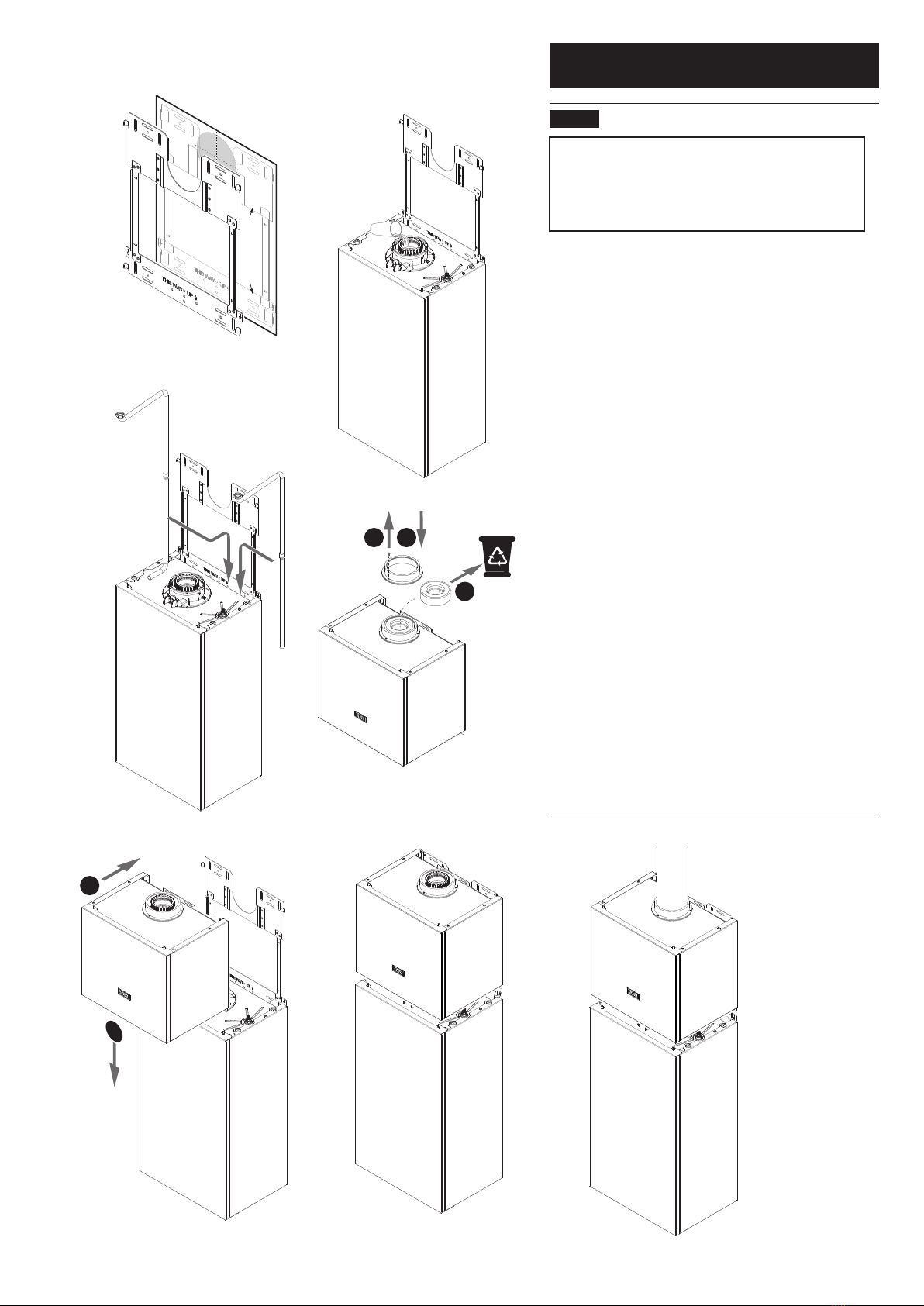
IMPORTANT: Follow the Installation & Servicing
Instructions supplied with the boiler to the point at
which the wall plate is tted, but do not mark the ue
position. The Assure FGHR must be tted on a at
vertical surface.
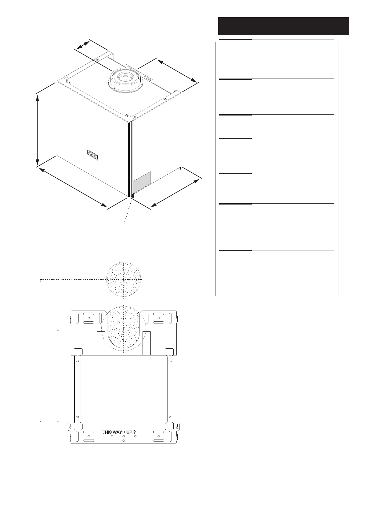
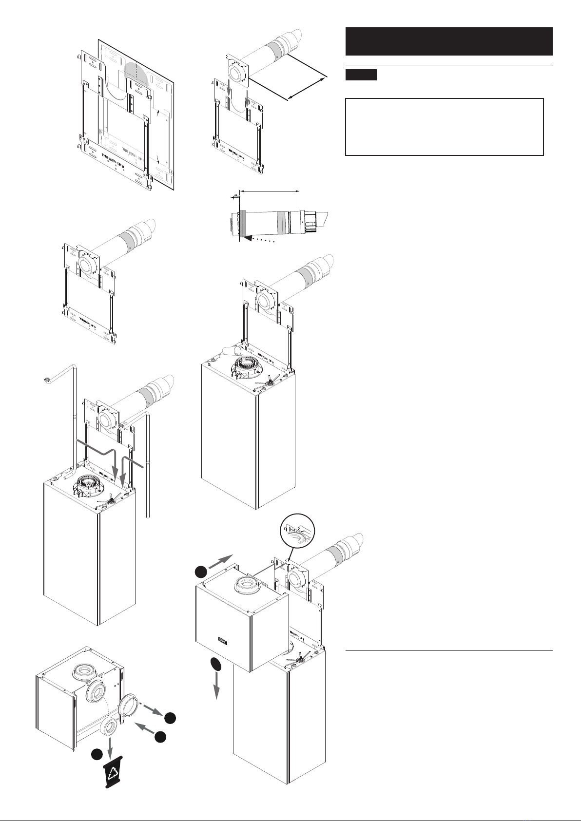
1. Align the Assure FGHR template on the wall (Fig. 16)
and mark the positions of suitable xing points on the
upper and lower plates of the wall frame.
2. Drill & plug the xing points. Cut the hole for the ue
Ø150 mm. Measure the wall thickness and add 17 mm.
Adjust the telescopic ue to length after locating and
securing it in the sliding collar with the screws supplied.
Tape and secure the ue (Fig. 17).
3. Apply the self-adhesive foam from kit 7215374 to the
rear face of the sliding collar (Fig. 18). Wrap the foam
around the ue twice. Engage the ue & collar in the
channels on the frame (Fig. 19).
4. Insert the ue into the Ø150 mm hole and secure the
frame assembly to the wall, ensuring the ue is uppermost
in the hole by pushing up the sliding collar. Hang the boiler
on the lower plate (Fig. 20). Prime the boiler trap by
pouring 300 ml of clean cold water into the central spigot.
Do not allow any water to spill into the air chamber.
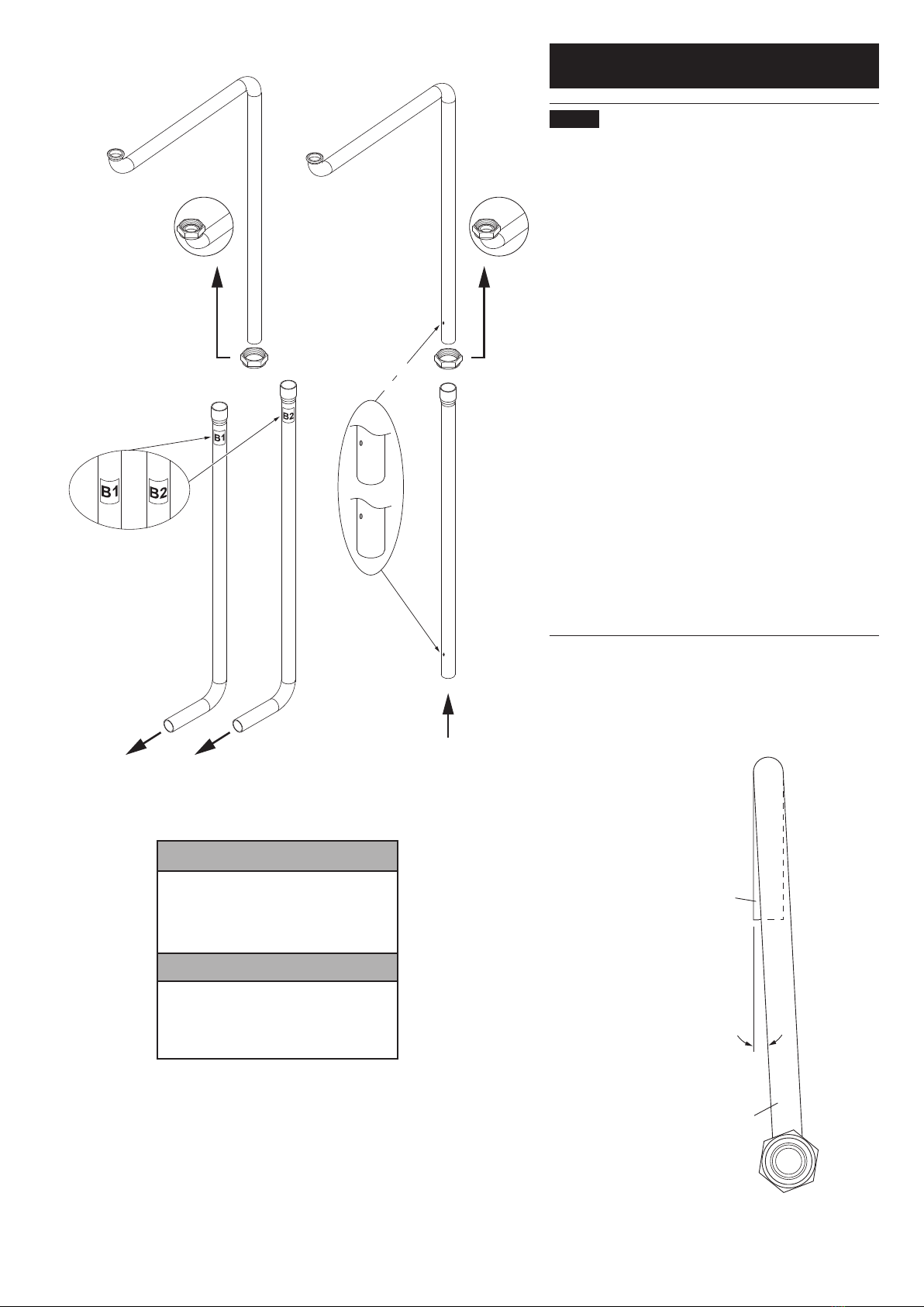
5. After identifying the FGHR inlet and ow pipes (Fig. 21),
manoeuvre them into place behind the boiler.
6. Undo the screws securing the rear ue adaptor and
remove the adaptor. Retain the screws & adaptor for reuse.
Extract the blanking cap and discard, recycling where
possible. Ret the adaptor and secure with the screws
previously removed (Fig. 22).
7. The Assure FGHR can now be tted (Fig. 23). Locate
the slots in the rear of the FGHR on the tabs of the
ue collar & upper plate. Lower the FGHR to engage
the ue connection on the underside with the boiler
adaptor, taking care to not displace the seals.
8. As the FGHR is lowered the ue & collar assembly
will slide down the channels to the lowest position.
9. Connect the ow & inlet pipes to the ttings on the
underside of the FGHR unit ensuring that the sealing
washers are in place.
10. Continue with the installation and commissioning of
the boiler.
Rear Flue - Drill Hole Ø125mm
Upper Plate
Lower Plate
Fig. 16
Template
Upper Plate
Lower Plate
Fig. 17
Wall
Thickness
+17 mm
Flue in Sliding
Collar
Wall Thickness +17 mm
Foam Seal
Fig. 18
Fig. 19
Fig. 20
Fig. 21
1
3
2
1
2
Flow Pipe
Inlet
Pipe
Keep Flue
Uppermost in
Hole
Priming
Fig. 22
Fig. 23
Locate Slots in
FGHR on Tabs
Direct Rear Flue
tted to FGHR