Bombas PSH FD 3.000 r.p.m. User manual

Tipo
Type
Type:
FD
3.000
r.p.m.
ELECTROPUMPS FOR SWIMMING POOLS
ELECTROBOMBAS DE PISCINAS
ELECTROPOMPES DE PISCINES
ELETTROPOMPE PER PISCINA
MANUAL DE INSTRUCCIONES PARA EL USO Y EL MANTENIMIENTO
HANDBOOK FOR USE AND MAINTENANCE
MANUEL D’INSTRUCTIONS POUR L’UTILISATION ET ENTRETIEN
MANUALE D’ISTRUZIONI PER L’UTILIZZO E LA MANUTENZIONE

2
FD -3.000
Norma DIN
4844-W8
1. DESCRIPCIÓN
1.1 Estas electrobombas han sido diseñadas para efectuar la recirculación de
aguas ligeramente tratadas en piscinas privadas y públicas.
1.2. CARACTERISTICAS TÉCNICAS
2. GENERALIDADES
2.1. Introducción. Este manual contiene las instrucciones necesarias para la
instalación, el uso y el mantenimiento de la electrobomba de piscinas. Para
obtener de ella las prestaciones que indicamos en las hojas de características,
es necesario que se cumplan y sigan correctamente todas las recomendacio-
nes dadas en este manual. Esto permitirá trabajar con un equipo seguro y du-
radero. El proveedor del equipo facilitará al usuario información comple-
mentaria, si éste la requiere.
2.2. Signos de seguridad en el manual de instrucciones. Aquellas instruccio-
nes que se refieren a los riesgos para las personas, se destacan con los dos sím-
bolos siguientes:
Otras instrucciones que estén relacionadas con el funcionamiento del equipo
ycuya falta de cumplimiento pueda dañarlo físicamente, se destacan con la
inscripción: ATENCIÓN
2.3. Placas de características (de CEEE 89/392 p.1.7.4.a). Lo que se indique
en la placa de características u otras instrucciones que colocamos sobre la uni-
dad, se observarán en este manual (Capítulo 1.2.)
2.4. Responsabilidad. El no cumplimiento de las instrucciones dadas por
BOMBAS PSH en este manual, para la elección, manejo, instalación, puesta
en marcha y mantenimiento de la unidad, libera al fabricante o distribuidor de
responsabilidades por accidentes posibles a las personas o daños causados al
resto de las instalaciones, ocasionando, además, la pérdida de la garantía.
2.5. Normas. Las electrobombas de piscinas de nuestra marca están fabricadas
de acuerdo con los requisitos esenciales de seguridad y salud establecidas en
las Directivas Comunitarias 89/392/CEE, 91/368/CEE (transpuestas al derecho
español en el Real Decreto 1435/1992 y 93/44/CEE).
3. INSTRUCCIONES GENERALES RELATIVAS A SEGURIDAD DEL USUARIO
3.1. Sólo se podrá garantizar la seguridad del servicio de la máquina su-
ministrada si su uso corresponde a lo indicado en los esquemas de
“ILUSTRACIONES”. Nunca se deberán sobrepasar las condiciones en este ma-
nual (capítulo 1.2. Características técnicas), así como las propias de la tarjeta
de características eléctricas indicadas en la bomba. Es obligatorio cumplir con
lo legislado por las Normas de Seguridad vigentes en cada país.
3.2. Asegurarse que el equipo se ha seleccionado adecuadamente a la
aplicación a la que va destinado y que su estado, instalación, puesta en
marcha y posterior uso sean correctos. Ver capítulo 1.2. (Características
Técnicas).
3.3. Las operaciones de instalación, reparación y mantenimiento se
harán siempre con el equipo desconectado de la red de alimentación
eléctrica.
3.4. Mientras el equipo esté en funcionamiento no puede ser desplazado,
ni corregida su posición. Estas operaciones se harán siempre a máquina
parada.
3.5. El accionamiento de los elementos eléctricos de conexión-desco-
nexión o seguridad no puede hacerse con presencia de humedad, po-
niendo especial cuidado en la que pueda existir en las manos del operario, en
su calzado o superficies de contacto.
3.6. Los elementos del equipo que durante su funcionamiento estén en
movimiento, o puedan alcanzar temperaturas peligrosas, se protegerán
con rejillas o carcasas que impidan el contacto accidental con ellos.
3.7. Los conductores eléctricos, o partes que puedan estar bajo tensión,
dispondrán del aislamiento adecuado. Otras partes metálicas del equi-
po se unirán solidariamente a tierra.
3.8. Los repuestos necesarios serán los originales del fabricante o los
recomendados por él. El uso de otros, o de originales rectificados por ter-
ceros no están permitidos y exhimen al fabricante o distribuidor de sus res-
ponsabilidades.
4. EMBALAJE, TRANSPORTE Y ALMACENAMIENTO
4.1. ATENCIÓN
El fabricante suministra el equipo protegido con el embalaje adecuado, para
que al transportarlo o almacenarlo no sufra daños que impidan su correcta ins-
talación y/o funcionamiento.
4.2. ATENCIÓN.El usuario, a la recepción del equipo, comprobará inicial-
mente estos puntos:
lEstado del embalaje exterior, si presenta signos de deterioros importantes, lo
hará constar formalmente a quien se lo entrega.
lVerificará también el estado del contenido; y si éste presentase desperfectos
que presumiblemente impidiesen su correcto funcionamiento, lo comunicará,
también formalmente, al proveedor en un plazo máximo de 8 días desde el de
la recepción.
4.3. ATENCIÓN.Las condiciones de almacenamiento serán tales que garanti-
cen el buen estado de conservación del equipo.
Señalamos por su especial importancia las de evitar ambientes de humedad
acusada u otros donde puedan producirse cambios bruscos de temperaturas
(producen condensaciones).
5. INSTALACIÓN Y MONTAJE
5.1. Emplazamiento. ATENCIÓN.El lugar de instalación de la motobomba tie-
ne que ser seco. En cualquier caso debe existir un desagüe en el suelo como
protección contra inundaciones. Si se monta la bomba en un local húmedo,
habrá que preveer un sistema de ventilación para evitar la formación de agua
de condensación. En el caso de montajes en espacios muy reducidos, el en-
friamiento del aire puede ser tan bajo que sea nacesario un sistema de airea-
ción y desaireación (ventilación) con el fin de no exceder la temperatura am-
biente de 40ºC. Es importante que la reserva de espacio sea suficiente para
poder desmontar el bloque motor en sentido horizontal y el filtro de cabellos
en sentido vertical (véase dibujo de espacio mínimo en fig. 1).
5.2. Localización/instalación. ATENCIÓN
El equipo o conjunto del grupo motobomba, filtro y válvula selectora, se ins-
talará cerca de la piscina a una distancia no superior a 3m de las tomas de su-
perficie (skimmer/rebosadero) y preferentemente a una cota de 0,5 m (nunca
superior a 3 m) bajo el nivel del agua, para conseguir su funcionamiento “en
carga”. La unión de la válvula selectora y de ésta con la boquilla y demás ac-
cesorios empotrados en la piscina se realizará prioritariamente en tubería de
P.V.C. El diámetro de las tuberías dependerá de los caudales. La velocidad má-
xima aconsejable del agua en las tuberías ha de ser de 1,2 m/s en aspiración
y2m/s en la impulsión. En cualquier caso, el diámetro de la tubería de aspi-
ración no debe ser inferior al diámetro de la boca de la bomba. La tubería de
aspiración debe ser perfectamente estanca y se ha de instalar con una pen-
diente descendiente (no inferior a 1/100), evitando de este modo la formación
de bolsas de aire.
En instalaciones permanentes, con la bomba situada en planos superiores al
nivel de agua, se procurará que la tubería de aspiración en su máximo reco-
rrido esté por debajo de los planos mencionados hasta alcanzar la vertical
coincidente con el eje de aspiración de la bomba.
La tubería de aspiración puede ser rígida o flexible con espiral de refuerzo que
evite la contracción. En instalaciones fijas, con la bomba por debajo del nivel
del agua, se colocará una válvula de cierre en aspiración y otra en impulsión.
5.3. Conexión eléctrica. ATENCIÓN
lCon carácter general, la instalación eléctrica estará, de acuerdo
con lo preescrito en los Reglamentos y disposiciones Técnicas Complementarias
que sean de aplicación y lo hará un instalador autorizado.
Precaución
por peligro
en general
Norma DIN
4844-W9
Precaución por
peligro descarga
eléctrica
MOTOR:
Potencia: Ver placa en el motor.
Aislamiento: Clase F.
Servicio: Continuo.
Protección: IP 55.
Tensión: Trifásica
(Ver placa de características).
Consumo: Ver placa en el motor.
Frecuencia: Ver placa en el motor.
R.P.M.: Ver placa en el motor.
Eje: Acero inoxidable.
Cojinete: Rodamiento de
bolas blindado.
Temperatura ambiente:
Mínimo 1ºC/Máximo 40ºC.
BOMBA:
Temperatura agua: Mínimo 1ºC
Máximo 40ºC.
Presión máxima: 2,1 bar.
Modelo turbina: Cerrada.
Tipo de sello: Retén mecánico.
Turbina: Tipo FD Bronce
Cuerpo de bomba: Tipo FD
Prefiltro: Tipo FD
Cestillo: Acero inoxidable.
Diámetro aspiración:
Según características de la bomba.
Diámetro impulsión:
Según características de la bomba.

3
ESPAÑOL
BOMBAS PSH
lLa red de alimentación dispondrá de conductores de neutro y tierra.
lLatensión de la red tiene que corresponder con la dada en la placa de ca-
racterísticas del equipo.
lLa sección de los conductores a utilizar tiene que ser suficiente para sopor-
tar, sin deterioro, la intensidad absorbida por el equipo (ver placa de caracte-
rísticas en el motor).
lAlconductor de tierra de la red se unirán eléctricamente todas las partes me-
tálicas del equipo que no deben estar bajo tensión, pero que accidentalmente
pudieran llegar a estarlo y sean accesibles a las personas (ver fig. 2).
Es obligatoria la instalación de un cuadro eléctrico de protección y maniobra
enel que se sitúan todos los elementos exigidos y otros recomendados, con
carácter general dispondrá de:
a. Interruptor general de corte omnipolar.
b. Dispositivos de protección contra cortacircuitos y sobrecargas en los mo-
tores.
c. Interruptor diferencial de alta sensibilidad, 30mA.
d. Otros, de mando y control.
Las características eléctricas de los dispositivos de protección y su regulación,
estarán de acuerdo con las de los motores a proteger y con las condiciones de
servicio previstas para éstos, y se seguirán las instrucciones dadas por el fabri-
cante (ver placa de características en el motor).
En los equipos hay que posicionar adecuadamente los puentes de interco-
nexiones de los devanados del motor (ver fig. 2). La entrada y salida de con-
ductores a la caja de bornas se hará mediante prensaestopas que garantizan la
ausencia de humedad y suciedad en ésta, por lo que estará provista de un cie-
rre estanco. Los conductores para su unión a bornas, estarán dotados de ter-
minales adecuados.
6. PUESTA EN MARCHA
Antes de poner el equipo bajo tensión, conectado a la red, se harán las
siguientes operaciones:
lVerificar que las condiciones eléctricas sean correctas.
lComprobar, manualmente, que la motobomba no está agarrotada.
6.1. Cebado de bomba. ATENCIÓN.Evitar el funcionamiento en seco de la
electrobomba. Con la bomba en aspiración, máximo 2 metros, (por encima
del nivel del agua de la piscina), antes de la puesta en marcha, retirar la tapa
prefiltro (66) y llenar lentamente con agua limpia hasta el nivel de la boca de
aspiración. Cerrar la tapa (66) (fig. 3) de nuevo y tomar la precaución que es-
té herméticamente cerrada.
ATENCIÓN.Con la bomba por debajo del nivel del agua de la piscina,
siempre con la tapa (66) herméticamente cerrada, llenar la bomba
abriendo lentamente la válvula de cierre de aspiración, teniendo abierta la vál-
vula situada en su impulsión.
6.2. ATENCIÓN.No se debe poner la bomba en marcha sin el filtro de grue-
sos y cabellos (64) (Fig. 3), ya que, de esta manera, podría obstruirse y quedar
bloqueada.
6.3. Sentido de giro ATENCIÓN.Asegurarse que el eje del motor gira libre-
mente: no poner en marcha si está bloqueado. Para este fin, las electrobom-
bas tienen una ranura en el extremo del eje, lado ventilador, que permite ha-
cerlo girar a mano con un destornillador.(Fig. 1) La turbina (55) puede
destornillarse si el motor arranca en sentido contrario. La rotación inversa pue-
de también incluso dañar el sello mecánico.
Arrancar pocos segundos el motor y controlar que el sentido de rotación co-
rresponde al indicado en la flecha situada en la tapa del ventilador. Si no fue-
ra así, es imprescindible avisar a un instalador autorizado (invertir la conexión
entre dos fases).
6.4. ATENCIÓN
Comprobar que el motor no supera el amperaje indicado en la placa de ca-
racterísticas (120) (Fig. 3) con un tester; en caso contrario regular con la vál-
vula situada en impulsión.
Evitaremos el funcionamiento prolongado de la electrobomba: descebada,
con la válvula cerrada o por falta de agua en aspiración.
7. MANTENIMIENTO / CONSERVACIÓN
Antes de cualquier manipulación, desconectar la alimentación eléctrica.
7.1. ATENCIÓN.
Controlar y limpiar periódicamente el cestillo (64) de la bomba.
Para extraer el cestillo (64) situar las válvulas en la posición de “cerrado”, así
como todas las demás válvulas del colector.Soltar la tapa (66) del prefiltro
(100), extraer el cestillo (64) y limpiarlo bajo un grifo de agua; “no golpear”,
para evitar su deterioro. Para ubicar nuevamente el cestillo (64), introducirlo
suavemente, hasta dejarlo en su posición primitiva. Colocar bien la junta (65)
de la tapa (66) y engrasarla con vaselina.
No introducir en el cestillo (64) productos químicos.
No olvidar que los cambios de posición de las válvulas se realizan siempre con
el motor parado.
7.2. ATENCIÓN.Sila bomba permanece parada por períodos largos, o si exis-
tiese peligro de heladas, se debe vaciar el cuerpo de la bomba (62), soltando
el tapón (69)/(103) de vaciado con sus juntas tóricas.
Antes de poner en marcha la bomba, colocar el tapón (69) con sus tóricas (68).
Llenar de agua el prefiltro (100) y comprobar con un destornillador que el mo-
tor no está bloqueado. Si el eje estuviese agarrotado, avisar a un técnico auto-
rizado.
En caso de inundación del motor, no intentar ponerlo en marcha; se avisará a
un electrotécnico autorizado, y éste desmontará el motor para proceder al se-
cado del mismo.
8. DESMONTAJE
8.1. ATENCIÓN
Antes de cualquier operación, todas las válvulas deben estar ce-
rradas, comprobando ésto procederemos a:
lDesconectar el interruptor general eléctrico e interruptor diferencial (a reali-
zar por especialista autorizado).
lSoltar y retirar los cables de alimentación de la caja de bornas (26), (Fig. 3).
lLiberar los manguitos de aspiración e impulsión.
lVaciar la bomba.
8.2. ATENCIÓN
Para desmontar la turbina (55), bloqueamos el eje (1) del motor ayudándonos
con una mordaza, al tiempo que giramos a derechas (sentido horario) para los
modelos FD 14, FD 15 Y FD 16 y a izquierdas (sentido antihorario) para los
modelos FD 17, FD 18, FD 19, FD 20, FD 21 Y FD 22 la tuerca (57) con una
llave quedando la turbina (55) disponible para sacarla del eje (1) ayudándonos
de un extractor. De esta forma queda libre la parte móvil de reten (74).
9. MONTAJE
ATENCIÓN
Todas las piezas que vayamos a acoplar deben estar limpias y en perfectas con-
diciones de uso.
Para el montaje de la bomba procederemos:
lMontar el sello mecánico (80). Presionar éste (74) hasta encajar en su aloja-
miento; previamente habremos lubricado el retén con agua.
lEnsamblar la turbina (55) en el eje (1) fijando ésta (55) con la chaveta (54), la
arandela (56) y la tuerca (57). De esta forma se consigue la unión de las dos
pistas del sello mecánico.
lFijamos el bloque motor al cuerpo de la bomba (62) mediante los tornillos
(63).
10. RECAMBIOS
Para la solicitud de cualquier pieza de recambio, precisar la denominación, el
número de posición en el plano de despiece (Fig. 3) y los datos de las placas
de características (120).
ADVERTENCIAS:
TODAS LAS OPERACIONES QUE SE REALICEN EN EL EQUIPO DEBERÁN
ESTAR HECHAS POR EL SERVICIO TÉCNICO OFICIAL O AUTORIZADO,
DE NO SER ASÍ, PERDERÁ TODA GARANTÍA Y RESPONSABILIDAD.
SI EL USUARIO UTILIZA EL EQUIPO DE FORMA NO ESPECIFICADA POR
EL FABRICANTE, LA PROTECCIÓN DEL EQUIPO PUEDE RESULTAR COM-
PROMETIDA, POR LO CUAL PIERDE LA GARANTÍA.
Fig. 1 - 2 __________________________________________________ Pág. 14
FD14 - 15 - 16__________________________________Fig. 3________Pág. 15
FD17 - 18______________________________________Fig. 3________Pág. 16
FD19__________________________________________Fig. 3________Pág. 17
FD20 - 21 - 22__________________________________Fig. 3________Pág. 18

4
FD -3.000
1. DESCRIPTION
1.1. These electropumps have been designed to recirculate lightly treated wa-
ter in private and public swimming pools.
1.2. Technical characteristics
2.GENERAL
2.1. Introduction. This Handbook contains the instructions necessary for ins-
tallation, use and maintenance of the swimming pool electropump. In order to
obtain the maximum performance shown in the Description of Characteristics,
it is necessary to fulfil and follow correctly all the recommendations given in
this-Handbook. This will allow operation with a safe and long-lasting piece of
equipment.
The equipment supplier will furnish the user with complementary information,
if required.
2.2. Safety signs used in the handbook
All instructions referring to possible risks to persons are highlighted by the fo-
llowing symbols:
Other instructions in relation to the functioning of the equipment with which
non-compliance could cause physical damages are highlighted with the war-
ning: ATTENTION
2.3. Nameplate ratings (EEC 89/392 P.1.7.4.A). The information given on the
nameplate or other instructions affixed to the unit, must be strictly complied
with. The content of these plates can usually be found in this Handbook
(Chapter 1.2.).
2.4. Liability. Failure to comply with the instructions given by BOMBAS PSH
in this Handbook, in relation to the choice, handling, installation, starting and
maintenance of the unit, shall release the manufacturer or distributor from all
liability in respect of accidents suffered by persons or damages caused to other
installations and, in addition, shall entail forfait of the warranty.
2.5. Standards. Our swimming pool electropumps are manufactured in accor-
dance with the necessary requeriments for safety and health set forth in
Community Directives 89/392/EEC,91/368/EEC (assimilated into Spanish Law
by Royal Decrees 1435/1992 and 93/44/EEC).
3. GENERAL INSTRUCTIONS IN RELATION TO USER SAFETY
3.1. Safety during operation of the machinery supplied can only be gua-
ranteed if it is used in accordance with the diagrams show “Illustra-
tions”. It must never exceed the working conditions and limits given in this
Handbook (Chapter 1.2. - Technical Characteristics). Compliance with the pro-
visions of Safety Standards in force in each country is mandatory.
3.2. Please ensure that the equipment selected is adequate for the used
for witch it is intented and that its condition, installation, starting and
subsequent use are correct. See chapter 1.2. (Technical Characteristics).
3.3. Installation, repair and maintenance operations will be carried out
in all cases with the equipment disconnected from the mains.
3.4. While the equipment is functioning, it cannot be moved or reposi-
tioned. These operations will be carried out at all times with the machi-
ne disconnected.
3.5. Pressing of the electrical on/off or safety elements will not be per-
formed where there is damp, and special care must be taken for user’s
hands to be dry, and also with footwear and surfaces with which the user is in
contact.
3.6. Those elements of the equipment which, when functioning, are in
movement or which could reach dangerous temperatures, will be pro-
tected with cages or casings which will prevent accidental contact with the sa-
me.
3.7. Electricity conductors, or parts which could carry current, will be
suitably insulated. Other metal parts of the equipment will be correctly
earthed.
3.8. Spare parts that may be necessary will be originals from the manu-
facturer or those recommended by the manufacturer. The use of others,
are not permitted and release the manufacturer or distributor from all liability.
4. PACKING, TRANSPORT AND STORAGE
4.1. ATTENTION.
The manufacturer supplies the equipment protected in suitable packaging, so
that it is not damaged during transport or storage thus ensuring its correct ins-
tallation and/or functioning.
4.2. ATTENTION.
The user, upon receipt of the equipment, will immediately check the following
points:
lCondition of the outside packaging, if this shows signs of serious deterioration,
he shall formally advise the person delivering the equipment.
lHe shall also check the condition of the contents; should this show defects
which would presumably prevent correct functioning, he shall also formally no-
tify the supplier within a period not exceeding 8 days from the date of delivery.
4.3. ATTENTION
Storage conditions must ensure the optimum preservation of the equipment.
Due to its particular relevance, we must stress that very damp atmospheres or
others where extreme changes in temperatures (which cause condensation)
must be avoided.
5. INSTALLATION AND ASSEMBLY
5.1. Location. ATTENTION.
The place where the electropump is to be located must be dry.In all events,
there must be a drain in the floor as a prevention against flooding. If the pump
is to be located in a damp place, a ventilation system must be provided in or-
der to prevent the formation of condensation.
In the case of very confined areas, cold air can reach a low temperature which
requires a ventilation system where by the it does not exceed 40ºC. It is im-
portant for there to be sufficient space to permit the motor block to be dis-
mounted horizontally and the hair filter vertically (see minimum space diagram
in fig. 1).
5.2. Positions / Installation
ATTENTION
The equipment or set of motor pump, filter and selection valve, will be insta-
lled near the swimming pool at a distance of no more than 3 m, from the sur-
face skimmers and preferably at a level of 0,5m (never more than 3m) below
the level of the water, in order to achieve its “under load” functioning. The se-
lection valve junction, and its connection to the nozzle and other accessories
incorporated in the swimming pool will preferably be made in PVC pipe.
Pipe diameters will depend on flows. The maximum water speed advisable in
the pipes will be 1.2 m/s in suction and 2m/s in impulsion. In any event, the
diameter of the suction pipe must not be less than the diameter of the pump
nozzle.
The suction pipe must be perfectly watertight and must be installed with a
downward inclination, thus avoiding the formation of air pockets. In perma-
nent installations, with the pump positioned at a higher level than that of the
water, it is advisable for the longest strech of the suction pipe to be below the
levels mentioned until it reaches the vertical pipe which coincides with the
pump suction line.
The suction pipe can be either rigid or flexible with a reinforced coil to avoid
contraction. In fixed installations, with the pump below the water level, a shut-
off valve will be placed on the suction pipe and another on the header pipe.
5.3. Connection to the mains
ATTENTION
lIn general terms, the electrical installation will fully comply with
the Regulations and Complementary Technical provisions appli-
cable and will be performed by an authorised Installer.
MOTOR:
Power rating: See motor plate.
Insulation: Class F.
Operation: Continuous.
Protection: IP 55.
Current: Triphase (see nameplate ra-
tings).
Consumption: See motor plate.
Frecuency: See motor plate.
R.P.M.: See motor plate.
Shaft: Stainless steel.
Bearing: Amoured ball bearing.
Atmospheric temperature:
Minimum1ºC - Maximum 40ºC.
PUMP:
Water temperature:
Minimum1ºC - Maximum 40ºC.
Maximum pressure: 2,1 bar.
Impeller model: Closed.
Type of seal: Mechanical.
Impeller: Type FD
Pump casing: Type FD
Prefilter: Type FD
Basket: Stainless Steel.
Suction diameter: According to the
pump characteristics.
Delivery diameter: According to the
pump characteristics.
Standard DIN
4844-W8
Danger
in general Standard DIN
4844-W9
Danger
of
electrocution

5
ENGLISH
BOMBAS PSH
lThe supply will have neutral and earth wires.
lThe mains voltage must correspond to that shown on the nameplate rating
for the equipment.
lThe earth wire to be used must be sufficient to take, without deterioration,
the current absorbed by the equipment (see nameplate).
lThe mains earth wire will be connected electrically to all metal parts of the
equipment which should not be under current, but which could accidentally
be affected by the same and which are accessible to persons (see figs. 2).
It is obligatory to install a protection and operation switchboard which will
contain all necessary and recommended elements. In general terms, it will
contain:
a. General cut-off or unipolar switch.
b. Short-circuit and overload protection devices for motors.
c. 30mA differential high sensitivity switch.
d.Others for monitoring and control.
The electrical characteristics of the protection devices and their regulation will
comply with those for the motors to be protected and with the service condi-
tions envisaged for these, and the instructions given by the manufacturer must
be followed (see nameplate).
lIn the case of equipment with triphase motors, the motor winding intercon-
nection bridges, must be suitably positioned (see figs. 2).
lConductor inlets and outlets at the bushing box will have stuffings to ensure
the absence of damp and dirt, and will therefore have a sealed casing.
lConductors will have suitable terminals for connection to the bushings.
6. STARTING
Before connecting the equipment to the mains, the following operations
will be carried out:
lCheck that the electrical conditions are correct.
lManually check that the motor pump is not jammed.
6.1. Pump priming. ATTENTION.“Avoid blind functioning of the electro-
pump”. With the pump in the suction position (above the water level of the
swimming pool), before starting, remove the prefilter cover (66) (fig. 3) and
slowly fill with clean water up to the level of the aspiration nozzle. Close the
cover (66) again and take care that it is hermetically closed.
ATTENTION.With the pump below the swimming pool water level, al-
ways with the cover (66) hermetically closed, fill the pump by slowly ope-
ning the aspiration cut-off valve, with the header valve in the open position.
6.2. ATTENTION.The pump must not be started without the lumps and hair
filter (item 64) (fig. 3) since this could cause obstruction and would block the
system.
6.3. Direction of rotation. ATTENTION.Ensure that the motor shaft turns fre-
ely; do not start the pump if it is blocked. For this purpose, electropumps have
agroove at the end of the shaft, on the ventilator side, which permits it to be
turned manually using a screwdriver (fig. 1).
In triphase motors, the impeller (55) can be unscrewed if the motors starts in
the opposite direction.
Counter-rotation can even damage the mechanical seal. Start the motor for a
few seconds and check that the direction of rotation coincides with that indi-
cated by the arrow on the ventilator cover.
Should this not be the case, it is absolutely necessary to advise the authorised
installer (invert the connections between two phases).
6.4. ATTENTION.
Check that the motor does not exceed the amperage indicated on the name-
plate rating (120) (fig. 3); otherwise, regulate using the header valve.
7. MAINTENANCE / CONSERVATION
Before touching, disconnect the electricity supply.
7.1. ATTENTION. Regularly check and clean the basket (64).
Toremove the basket, place the valves, and all other valves, in the “off”
position. Loosen the cover (66) of the prefilter (100), remove the basket
(64) and clean it under running water,“do not strike” to avoid its dete-
rioration. To re-place the basket (64), introduce it gently, untill it is in its
original position. Correctly place the joint (65) of the cover (66) and gre-
ase with vaseline.
Do not place the basket (64) in chemicals. Please remember that changes
in position of the valves will be made at all times with the motor switched
off.
7.2. ATTENTION
Ifthe pump is switched off for long periods of time, should there be a dan-
ger of frost, the pump casing (62) should be emptied, by losening the plug
(69)/(103) along with their O-ring seals. Before starting the pump, replace
the plug (69)/(103) and their O-ring seals. Fill the prefilter (100) with wa-
ter and check with a screwdriver that the motor is not jammed. If the shaft
has seized up, call a qualified technician. In the event of the motor floo-
ding, do not try to start it; call an electrician to dismount the motor in or-
der to dry it.
8. DISMOUNTING
8.1. ATTENTION
Before performing any operation, all valves must be in the
“off” position: having checked this:
lDisconnect the general electricity switch and the differential switch (this
must be done by an authorised specialist).
lLoosen and remove the supply cables on the connection box (26) (fig. 3).
lRelease the aspiration and impulsion sleeves.
lEmpty the pump.
8.2. ATTENTION
In order to dismount and assemble the electropump, please see the detail
drawing. (Fig. 3). In order to remove the motor from the hydraulic casing
(62), remove the four screws (45)(39)(52) and lever so as to separate one
part from the other one.
In order to dismount the impeller (55) hold the motor shaft (1) with the aid
of a clamp, while rotating the nut (57) to the left (anticlockwise) for mo-
dels FD17, FD 18, FD 19, FD 20, FD 21, and FD 22, and to the right
(clockwise) for models FD 14, FD 15 and FD 16, with a wrench, thus re-
leasing the impeller (55). In this way the mechanical seal (74) is released,
too.
9. ASSEMPLY
ATTENTION
“All parts to be assembly must be clean and in perfect condition for use”.
In order to assemble the pump:
lAssemble the mechanical seal (80). Press this (43) until its locates into
the space; the seal will have been lubricated with water beforehand.
lAssemble the impeller (55) on the shaft (1), affixing it with the key (57),
impeller washer (56) and impeller nut (57). In this way, the two halves of
the mechanical seal are joined.
lFix the motor to the pump casing (62) by means means of the four
screws (63), impeller washer (56) and pump housing nut (107).
10. SPARE PARTS
To order any spare parts, indication must be given of the part, number
shown on the detail drawing (fig 3) and nameplate ratings (120).
WARNING:
ALL THE ADJUSTEMENTS THAT ARE MADE TO THE EQUIPMENT
MUST BE MADE BY THE AUTHORIZED TECNICAL SERVICE. IF NOT
THE GUARANTEE IS VOID AND WE ACCEPT RESPONSABILITY.
IF THE EQUIPEMENT IS USED FOR ANY OTHER MEANS THAN SPECI-
FIED BY THE MANUFACTURED, THE PROTECTION OF THE EQUIP-
MENT COULD FAIL, THEREFORE LOSING THE COVER OF GUARAN-
TEE.
Fig. 1 - 2 __________________________________________________ Pág. 14
FD14 - 15 - 16__________________________________Fig. 3________Pág. 15
FD17 - 18______________________________________Fig. 3________Pág. 16
FD19__________________________________________Fig. 3________Pág. 17
FD20 - 21 - 22__________________________________Fig. 3________Pág. 18
Table of contents
Languages:
Popular Swimming Pool Pump manuals by other brands
TIP
TIP STEAM 35000 INV Translation of original operating instructions
Jacuzzi
Jacuzzi J-HI27C Installation and operating instructions
Calpeda
Calpeda NMP operating instructions
Pentair Pool Products
Pentair Pool Products SuperFlo Swimming Pool Pump Installation and user guide
AES
AES EFI Series Installation and operation manual

Pentair
Pentair WHISPERFLO VS 1500 owner's manual
Jula
Jula 952-007 operating instructions
Pentair Pool Products
Pentair Pool Products Eagle owner's manual
COMFORTPOOL
COMFORTPOOL BASIC 6 manual

Espa
Espa Evopool SilenPlus ControlSystem instruction manual
Davey
Davey StarFlo DSF150CE Installation and operating instructions
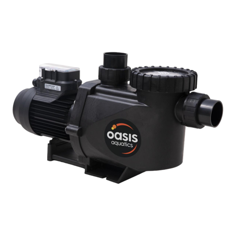
Oasis Aquatics
Oasis Aquatics V Series Installation and operation manual

