Baytex 10m CLIPFRAME GABLE END User manual
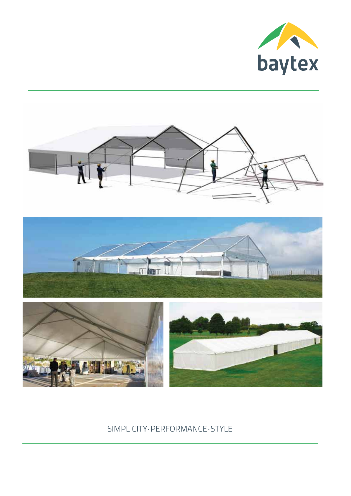
10m CLIPFRAME GABLEEND
Assembly Instructions
New Zealand
52 Newton Street,
PO Box 4370, Mount Maunganui
New Zealand
tel +64 7 579 0190
fax +64 7 579 0194
www.baytex.co.nz
Australia
tel 02 4340 4144
mob 0400 312 314
10m CLIPFRAME GABLEEND
Assembly Instructions
1/15
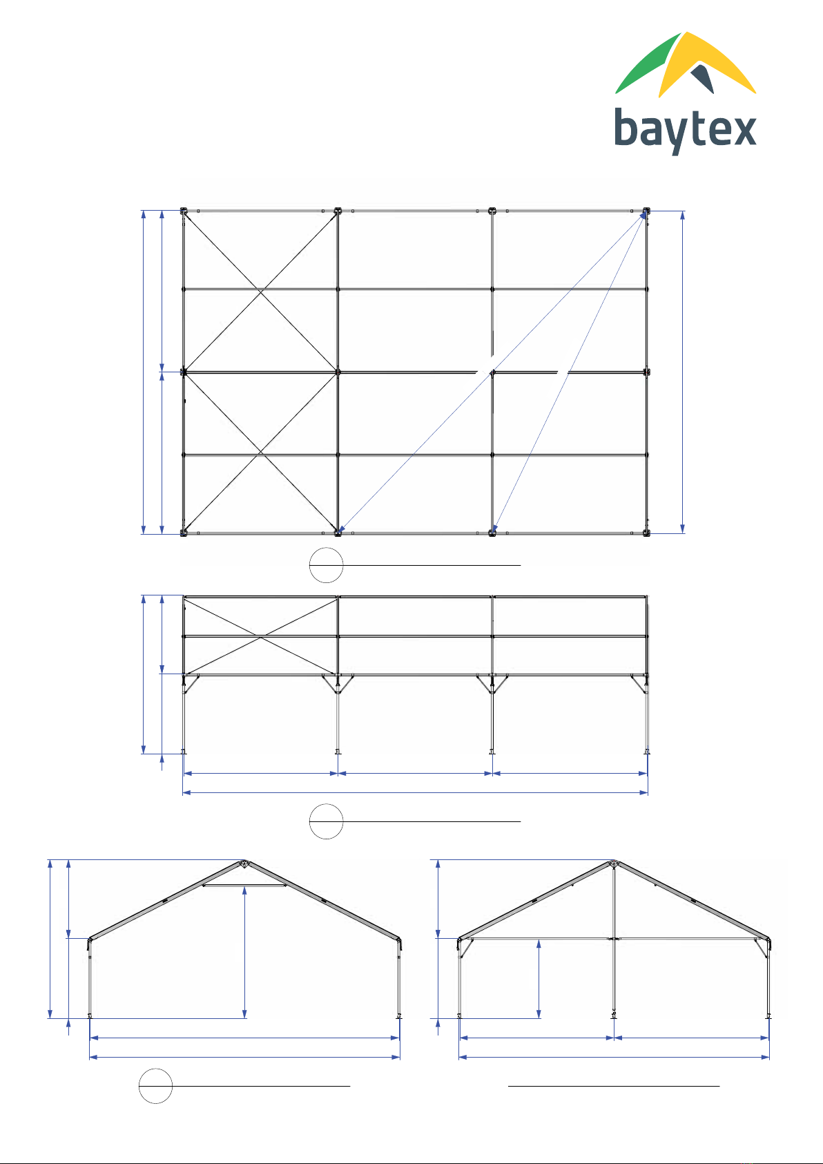
4971
CTRS
4971
CTRS
24362480
Top
of
Eave
4916
Top
of
Apex
14978
Outside
Eaves
Scale 1:85
003/2
-
Side
View
4971
CTRS
5004
to
Outside
Eave
5004
to
Outside
Eave
10007
Outside
Eaves
Scale 1:85
003/1
-
Plan
View
9942
Leg
Ctrs
11115
14060
Leg
Ctrs
Gable
End
Portal
Gable
End
Portal
4971
CTRS
2480
Top
of
Eave
2436
4916
Top
of
Apex
10007
Outside
Eaves
003/4
-
Gable
End
Portal
2444
4971
CTRS
9942
CTRS
2480
Top
of
Eave
2436
4916
Top
of
Apex
10007
Scale 1:85
003/3
-
Mid
Portal
4087

10m CLIPFRAME GABLEEND
Parts List
2/15
Mid
Bay Hardware
List
(Bay
Quantity
=
1)
Ref
.
Part Name
Qty
Number
Part
2
Apex
Connector
Mid
-
Channel
Tube
26˚
1
70
.707
5
Ø65
Shoulder
Connector 26˚
2
70
.840
6
Tensioner
Set
2
a
-
(x1)
16mm
Reid Bar
Nut
-
b
-
(x1)
Tensioner Hook
70
.841
c
-
(x1)
Tensioner Bracket
Hook
Rod
72
.716
7
10m
Side
Rafter
-
Channel
Tube
2
70
.510
.006
8
Ø
65
Ridge
Purlin
5m
1
70
.788
9
Ø
50
Intermediate
Purlin
5m
2
70
.792
10
Ø
65
Eave
Purlin
5m
(2
Way)
2
70
.787
12
Base Rail
-
4.97m
2
70
.785
13
Ø
25
Brace
bar
4
70
.742
14
10m
Apex
Brace
1
70
.510
.016
16
Ø65
Leg -
2
.4m
,
180˚
2
70
.783
18
Ø
65mm
Base
Foot
2
70
.741
19
Roof
Brace
Cable
Set
0
70
.510
.023
Mid
Bay
Fabric
List
A
10m
x
5m
Mid Roof
1
70
.310
.660
C
5m
x
2
.4m
Wall
2
60
.025
End
Bays
Hardware
List
Ref
.
Part Name
Qty
Number
Part
1
Apex
Connector
GE - Channel
Tube
26˚
2
70
.707
2
Apex
Connector
Mid
-
Channel
Tube
26˚
1
70
.707
3
Ø65
Corner
Connector LH
26˚
2
70
.845
4
Ø65
Corner
Connector
RH 26˚
2
70
.846
5
Ø65
Shoulder
Connector 26˚
2
70
.840
6
Tensioner
Set
8
a
-
(x1)
16mm
Reid Bar
Nut
-
b
-
(x1)
Tensioner Hook
70
.841
c
-
(x1)
Tensioner Bracket
Hook
Rod
72
.716
7
10m
Side
Rafter
-
Channel
Tube
6
70
.510
.006
8
Ø
65
Ridge
Purlin
5m
2
70
.788
9
Ø
50
Intermediate
Purlin
5m
4
70
.792
10
Ø
65
Eave
Purlin
5m
(2
Way)
4
70
.787
11
10m
Ø
50
Gable
End
Adjustable
Eave
4
70
.510
.018
12
Base Rail
-
4.97m
8
70
.785
13
Ø
25
Brace
bar
12
70
.742
14
10m
Apex
Brace
1
70
.510
.016
15
Ø65
Leg -
2
.4m
,
90˚
4
70
.782
16
Ø65
Leg -
2
.4m
,
180˚
2
70
.783
17
10m
Gable
End
Upright
Set
-
2
.4m Leg
2
a
-
(x1)
10m Gable Upright Leg
,
and
70
.510
.018
b
-
(x1)
Ø65mm
Adjustable
Leg
Base
,
and
70
.797
c
-
(x1)
Tractor Clip
(AG272)
-
18
Ø
65mm
Base
Foot
8
70
.741
19
Roof
Brace
Cable
Set
1
70
.510
.023
End
Bays
Fabric
List
A
10m
x
5m
Mid Roof
2
70
.310
.660
B
10m
Gable
End
Roof
(4
Pieces)
1
70
.310
.630
C
5m
x
2
.4m
Wall
8
60
.025
7
5
3
18
2
1
12
10
12
11
4
13
15
16
17a
17b
9
14
3
4
11
17c
1
19
10
5
8
End
Bays
7
5
18
2
10
13
16
9
14
19
10
5
8
12
Mid
Bay
6a
6b
6c
17c
C
C
Mid
Bay
C
C
B
B
A
C
B
B
C
A
C
C
C
C
End
Bays
A

10m CLIPFRAME GABLEEND
Parts List
3/15
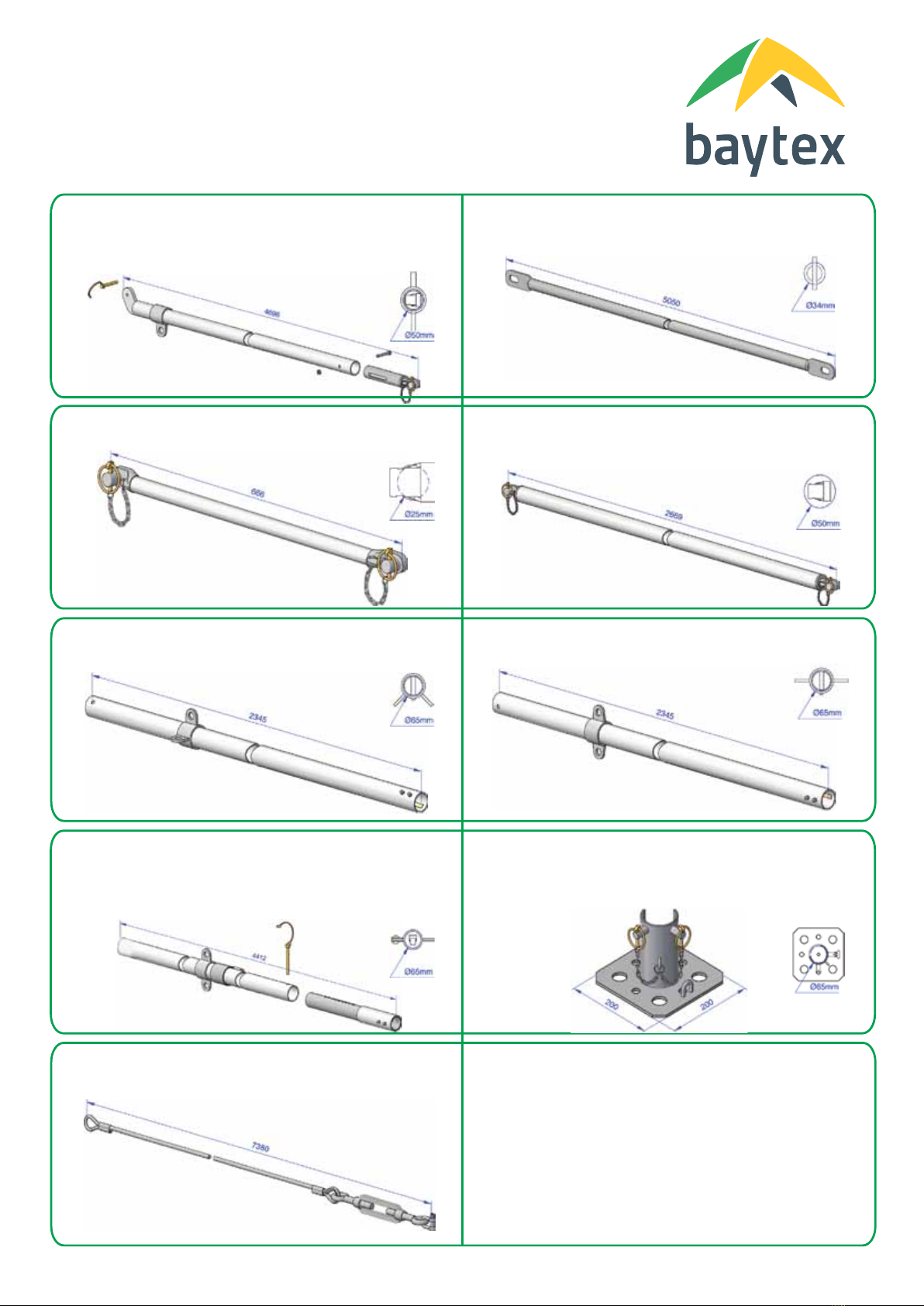
1. Apex Connector GE - Channel Tube 26˚
- To use with Channel Tube rafter
3. Ø65 Gable Connector LH 26˚
- To use with Channel Tube rafter and Ø65mm Leg
5. Ø65 Shoulder Connector 26˚
- To use with Channel Tube rafter and Ø65mm Leg
7. 10m Side Rafter - Channel Tube
2. Apex Connector Mid - Channel Tube 26˚
- To use with Channel Tube rafter
4. Ø65 Gable Connector RH 26˚
- To use with Channel Tube rafter and Ø65mm Leg
6. Tensioner Set
- Includes: (x1) 16mm Reid Bar Nut, (x1) Tensioner Hook
(x1) Tensioner Hook Adjuster
8. Ø 65 Ridge Purlin 5m
- 5m Bay
9. Ø 50 Intermediate Purlin 5m
- 5m Bay
10. Ø 65 Eave Purlin 5m (2 Way)
- - 5m Bay, 2 way Brace Collar
10m CLIPFRAME GABLEEND
Parts List
4/15
11. 10m Ø 50 Gable End Adjustable Eave
- Includes: (x1) Gable End Eave Bar, (x1) Adjustable
Eave Joint, (x1) M8 x 60 Hex Setscrew
(x1) M8 Nyloc Nut, (x1) Lynch Pin, (x1) Tractor Pin
(x1) Key Ring & Chain Set
13. Ø 25 Brace bar
- Includes: (x1) Brace Bar, (x2) Lynch Pin
(x2) Key Ring & Chain Set
15. Ø65 Leg - 2.4m, 90˚
- 90° Brace Collar
17. 10m Gable End Upright Set - 2.4m Leg
- Includes: (x1) Gable Upright Leg, (x1) Adjustable
Leg Base, (x1) Lynch Pin, (x1) Tractor Clip
(x1) Key Ring & Chain Set
- To use with Ø65mm Leg
12. Base Rail - 4.97m
14. 10m Apex Brace
- Includes: (x1) Apex Brace Bar, (x2) Lynch Pin
(x2) Key Ring & Chain Set
16. Ø65 Leg - 2.4m, 180˚
- 180° Brace Collar
18. Ø 65mm Base Foot
- Includes: (x1) Base Fitting, (x2) Lynch Pin, (x1) Key Ring &
Chain Set
- To use with Ø65mm Leg
19. Roof Brace Cable Set
- Includes: (x4) Ø5mm Cable, (x4) Turnbucle
(x4) Shackle

10m CLIPFRAME GABLEEND
Staking / Ballasting Options
5/15
1200 nominal
For
Max
.
Capacity
Pegs
Must
be
Driven
Vertically
A
x2
Pegs
(Ø25x800mm)
per
Base
Foot
B
Ballast 350kg
per
Base
Foot
attach
to
Foot
and Shoulder
Connector
C
x2
Pegs
(Ø25x800mm)
per
Base
Foot
+ Guyed
to
x2
Pegs
A
B
C
0km/h
10km/h
20km/h
30km/h
40km/h
50km/h
60km/h
70km/h
80km/h
90km/h
100km/h
Wind
Speed
Recommended
Staking
Options
.
Based
on
average
Soil Conditions
.
Consider
Location factors
eg:
on Exposed
Hilltop
,
limit
speed
to
50% of above
.
In
poor
soil
use
more
stakes
or
longer
stakes
.
Over
50km/h
-
All
Walling
to
be fitted
and
closed
Over
80km/h
-
All
Fabric
to
be
Removed
from
Frame
Frame
may
be
left
standing
350kg
Ballast
Minimum
Staking
for
each Leg of
typical
10m
x
5m
Bay
Typical
Stake
Capacity
250kg
in
average
soil
conditions
1
stake
250kg
Ballast
500
350kg
Ballast
0
.55m
x
0
.55m
x
0
.5m
Concrete
Block
.
Tied
to
base
with
ground
plate
550
550
Nominal
Stake
Capacity
250kg
.
2
Stakes
per base
.
1
.5
x
safety
factor
.
Nominal
Stake
Capacity
250kg
.
2
Stakes
per base
.
+
2
Stakes
per
outguy
1
.5
x
safety
factor
.
Ballast Tie
(use
non
slip
pad
under
ballast
ties)
engineered engineered engineered
estimated estimated
700kg
Ballast
estimated
Double
up
for
increased
wind
speed
10m CLIPFRAME GABLEEND
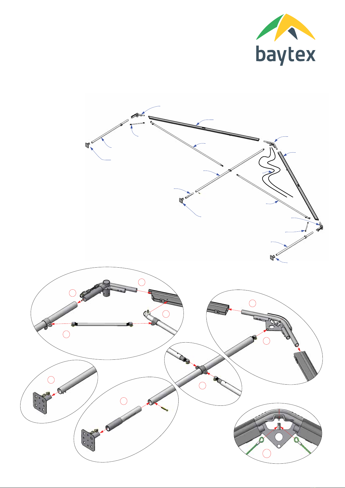
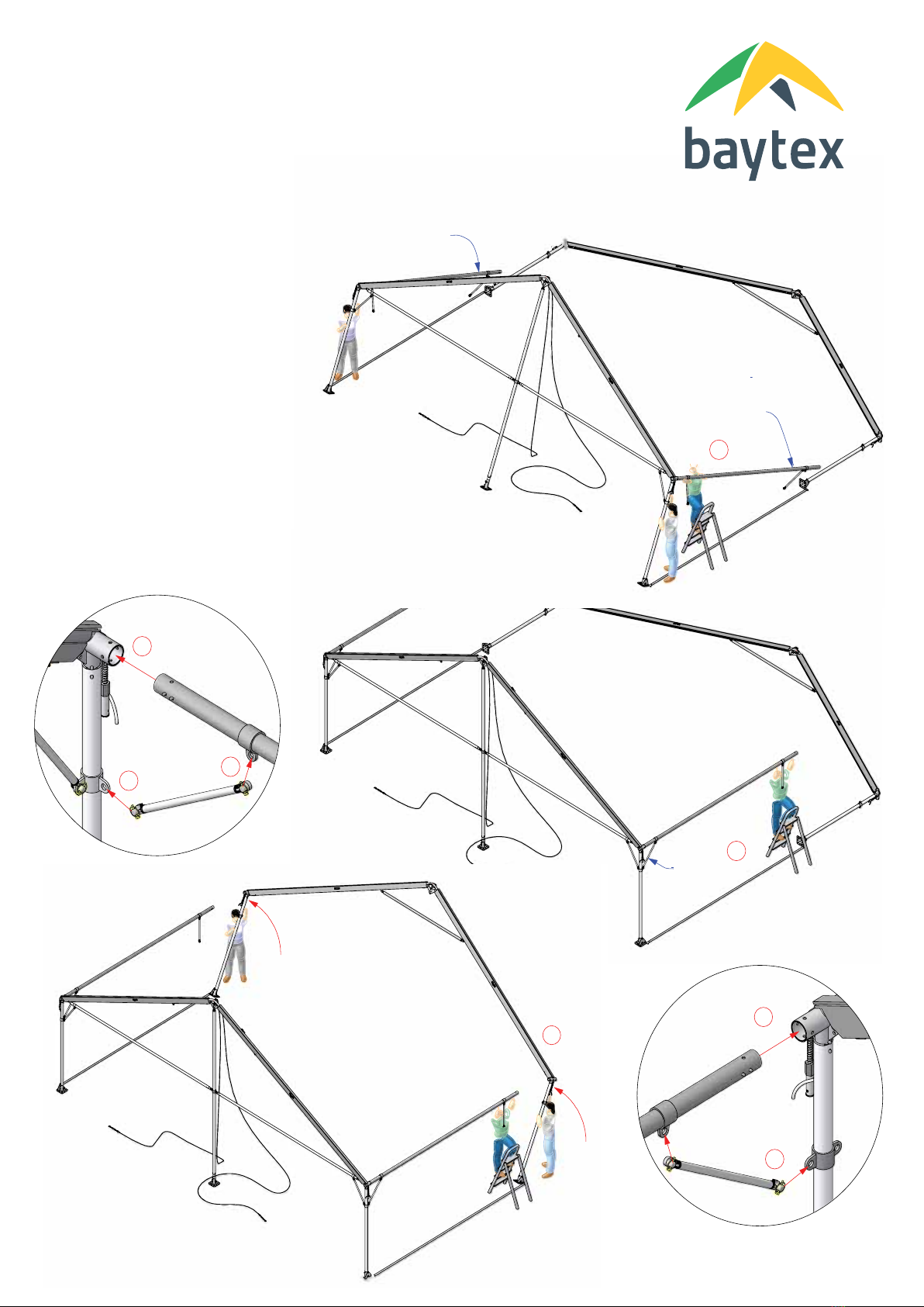
Gable End Frame Portal Assembly
6/15
Assemble
Gable Portal
10m
CF
Rafter
70
.510
.006
Apex
Connector
GE
70
.844
10m
CF
Rafter
70
.510
.006
10m
CF
Gable
End
Eave
70
.510
.018
10m
CF
Gable
End
Eave
70
.510
.018
Ø65mm Leg
-
2
.4m
90º
70
.782
Ø65
Corner
Connector
LH
70
.845
10m
Gable
End
Upright
70
.510
.018
Ø65
Adjustable
Leg
Base
70
.797
Ø65mm
Base
Foot
70
.741
Ø25
Brace
bar
70
.742
Ø65mm
Base
Foot
70
.741
Ø65mm
Base
Foot
70
.741
Ø65mm Leg
-
2
.4m
90º
70
.782
Ø65
Corner
Connector
RH
70
.846
Ø25 Brace Bar
70
.782
Brace
Wires
70
.510
.023
3
.
Join
Rafters
to
Apex
-
Use
Button
Lock
note: Gable
End
Apex
1
.
Join
Shoulder
Connector
to Rafter
-
Use
Button
Lock
note: Left &
Right
Shoulders
for
Gable
Portal
2
.
Join
Leg
to
Shoulder
Connector
-
Use
Button
Lock
note:
corner
leg
has
90º
collar
4
.
Join
Base
Fitting
to
Leg
-
Use
Button
Lock
note: orientate
pins
to
outside
5
.
Join
Gable Upright
to
Apex
-
Use
Lynch
Pin
6
.
Join
Gable
Eave
to
Rafter Near
Eave
-
Use
Tractor
Pin
7
.
Join
Gable
Eave
to
Upright
-
Use
Lynch
Pin
8
.
Join
Base
Plate
& Adjustable
Leg
to Upright
-
Use
Button
Lock &
Tractor
Pin
10
.
Attach
2
Roof
Brace
Cables
to
Apex
9
.
Join
Brace
Bar
to
Leg &
Gable
Eave
-
Use
Lynch
Pin
1
2
3
4
5
6
7
8
9
10

10m CLIPFRAME GABLEEND
Mid Frame Portal Assembly
7/15
Assemble
Mid Portal
10m
CF
Rafter
70
.510
.006
Apex
Connector
Mid
70
.707
10m
CF
Rafter
70
.510
.006
Ø65mm Leg
-
2
.4m
180º
70
.783
Ø65
Shoulder
Connector
70
.840
Ø65mm
Base
Foot
70
.741
Ø65mm
Base
Foot
70
.741
Ø65mm Leg
-
2
.4m
180º
70
.783
Ø65
Shoulder
Connector
70
.840
10m
Apex
Brace
70
.510
.016
3
.
Join
Rafters
to
Apex
-
Use
Button
Lock
note: Mid
Apex
1
.
Join
Shoulder
Connector
to Rafter
-
Use
Button
Lock
2
.
Join
Leg
to
Shoulder
Connector
-
Use
Button
Lock
note:
side
leg
has
180º
collar
4
.
Join
Base
Fitting
to
Leg
-
Use
Button
Lock
note: orientate
pins
to
outside
6
.
Attach
2
Roof
Brace
Cables
to
Apex
Pin
if Portal
is adjacent
to
a
Braced
Bay
1
2
3
4
6
Press
this
button
Engage
lead
button
Press
this
button
Engage
lead
button
Press
this
button
Engage
lead
button
5
.
Join
Apex
Brace
to
Rafters
-
Use
Lynch
Pin
5

Gable
End
Portal
Mid
Portal
Gable
End
Portal
Layout
Bar
Layout
Bar
5m 5m
10m
10m
1
.
Assemble
Portals
on
ground
in
position
ready
for
rotating
up
Base
Fitting
setout
triangle
slides
onto
base
fitting
pin
Base
fitting
lynch
pin
to
secure
triangle
inplace
Layout
bar
pin
slides
into
triangle
fitting
tube
2
.
Attach
Layout
Bar
&
triangles
to
first & second
portals
.
secure
with
lynch
pin
3
.
Gable
Fabric
can
be
Installed
at
this
stage
-
refer
page
13
1
2
4
Keep
Layout
Bars
in
place
untill
bay
is
complete
5m
Layout
Bar
4
.
Rotate
First
Portal
Up
3
10m CLIPFRAME GABLEEND
Portal Layout
8/15
Ø25mm
Brace
Bar
70
.742
4
Ø65mm
Eave
Purlin
5m
(2way)
70
.787
Ø65mm
Eave
Purlin
5m
(2way)
70
.787
1
10m CLIPFRAME GABLEEND
Portal Set Up
9/15
1
.
Join
Eave
Purlins
to
First
Portal
-
Use
Button
Locks
2
.
Join
25mm
Brace
Bars
to
Eave
Purlins
-
Use
Lynch
Pins
3
.
Join
25mm
Brace
Bars
to
Leg
-
Use
Lynch
Pin
4
.
Rotate
First
Portal
to
Vertical
Support
Eave
near
Second
Portal
5
.
Rotate
Second
Portal
to
Vertical
6
.
Join
Second
Portal
to
Eaves
-
Use
Button
Lock
7
.
Join
Brace
Bar
to
Second
Portal
-
Use
Lynch
Pin
70
.110
.500
5
2
1
3
7
6
7

www.baytex.co
.nz
simplicity
- performance - style
10/15
Baytex Manufacturing
Co
Ltd
10m
Gable End Clipframe Marquee
Purlin
&
Brace
Wire
Installation
28
May
2014
70
.110
.500
10m
CF
GE
Erecting
Manual
.vwx
Ø65mm
Ridge
Purlin
5m
70
.788
1
.
Hook
Ridge
Purlin
onto
First
Portal
Apex
note:
curved
hook
2
.
Rotate
Ridge
Purlin
up
to
Second
Portal
Apex
-
Use
Purlin
Fork
.
keep
square
to
purlin
-
twist
Purlin
Fork
to
reduce
sliding
1
3
.
Hook
Ridge
Purlin
into
Second
Portal
Apex
-
Ensure
Engaged
4
.
Install
Intermediate
Purlins
-
same
process
as
Ridge
Purlin
Keep
Layout
Bars
in
place
untill
bay
is
complete
5
.
Attach
Roof
Brace
Wires
to
Shoulders
-
Use
Shackle
-
Do
not
fully
tension
turnbuckle
until
roof fabric
is
in
place
.
2
3
1
Ø50mm
Intermediate
Purlin
5m
70
.792
4
5
2
5
Adjust Brace Wires to
square-up Frame
10m CLIPFRAME GABLEEND
Purlin & Brace Wire Installation
10/15

1
Layout
Bar
Layout
Bar
10m CLIPFRAME GABLEEND
Continued Frame Assembly
1
.
Move
Layout
Bars
to
Next
Bay
-
keep
in
place
until
bay
complete
2
.
Continue
Assembling
Each
Bay
in
same process
as
first
.
Consider
braced
bay
placements
.
-
Assemble
Portal
on
Ground
-
Attach
Layout
bars
-
Attach
Eave
Purlins
&
Brace
Bars
-
Rotate Portal
Up
&
join
to
Eave
Purlins
&
Brace
bars
-
Attach
Ridge
Purlin &
Intermediate
Purlins
-
Fasten
Brace
wires
if
applicable
3
.
Peg
down
Base Feet
-
x2
Marquee
Pegs
per
Foot
-
Use
Mallet
2
Stake or
Ballast
Frame
before
Fabric
Installed
11/15

10m CLIPFRAME GABLEEND
Roof Fabric Installation
12/15
2
4
6a
1
.
Throw
Pull
Over Ropes
Across
2
.
Attach
Pull
Over
Ropes
to
Roof 'D'
-
hook
facing fabric
3
.
Fit
Keder Feeder
in
Rafter end
-
optional
part
-
secure
with
hook
around
leg
5
.
Pull
Panel
Evenly
4
.
Engage
Keder
in
Rafter Extrusion
-
feed
through
Keder Feeder
1
5
3
6
.
Tension
Mid
Panels
6a
.
Mk2 -
Use
Packlocks
6b
.
Mk3
Tension
System
6b
Stake or
Ballast
Frame
before
Fabric
Installed
Optional
Keder
Feeder
4
2

3
10m CLIPFRAME GABLEEND
Gable Fabric Installation
13/15
2
.
Engage
Keder
in
Rafter Extrusion
3
.
Pull
Panel
to
Apex
4
.
Lace
Gable together
1
.
Attach
Pull
Over
Ropes
to
Gable 'D'
5
.
Tension
Gable Panels
5a
.
Mk2 -
Use
Packlocks
5b
.
Mk3
Tension
System
1
24
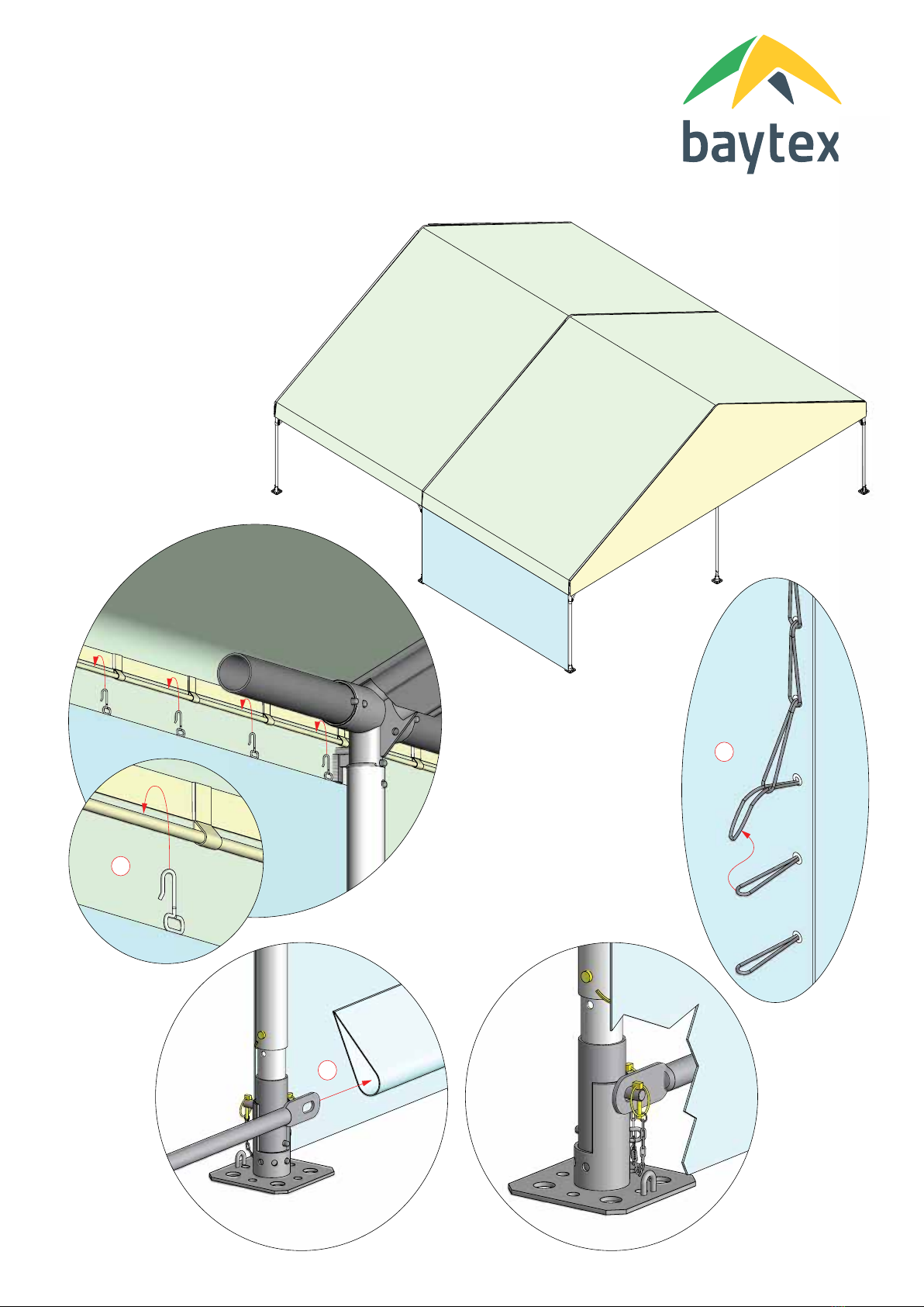
10m CLIPFRAME GABLEEND
Wall Fabric Installation
14/15
2
.
Lace
Walls together
behind
leg
3
.
Insert Base
Rail
in
Pocket
4
.
Attach
Base
Rail
to
Base Foot
-
Use
Lynch
Pin
1
.
Hook
Wall onto
Wall
cord of
Roof
Pockets
to
inside
2
1
3
4

General
Rules
-
Gable end
portal each
e
nd
(
Red
)
-
Mid
portals
in
between
(
Black
)
-
Roof brace
wires
each end
bay
(over
20m)
-
Maximum
4
bays
unbraced
in
succession
.
1
.
Plan
Site
Layout
,
Marquee
Length
and
bays
to
be
braced
5m
Bay
5m
Bay
5m
Bay
Gable
End
Gable
End
10m
5m
Bay
5m
Bay
5m
Bay
5m
Bay
Gable
End
Gable
End
10m
5m
Bay
5m
Bay
5m
Bay
5m
Bay
5m
Bay
Gable
End
Gable
End
10m
5m
Bay
5m
Bay
Gable
End
Gable
End
10m
5m
Bay
5m
Bay
5m
Bay
5m
Bay
5m
Bay
Gable
End
Gable
End
10m
5m
Bay
5m
Bay
5m
Bay
5m
Bay
5m
Bay
Gable
End
Gable
End
10m
5m
Bay
5m
Bay
5m
Bay
Gable
End
Gable
End
10m
10x10
5m
Bay
5m
Bay
5m
Bay
5m
Bay
5m
Bay
Gable
End
Gable
End
10m
5m
Bay
5m
Bay
Gable
End
Gable
End
10m
5m
Bay
5m
Bay
5m
Bay
5m
Bay
5m
Bay
5m
Bay
Gable
End
Gable
End
10m
5m
Bay
5m
Bay
Gable
End
Gable
End
10m
5m
Bay
5m
Bay
10x15
10x20
10x25
10x30
10x35 10x40
10x45
5m
Bay
5m
Bay
5m
Bay
5m
Bay
5m
Bay
Gable
End
Gable
End
10m
5m
Bay
5m
Bay
Gable
End
Gable
End
10m
5m
Bay
5m
Bay
10x50
5m
Bay
5m
Bay
5m
Bay
5m
Bay
5m
Bay
5m
Bay
Gable
End
Gable
End
10m
5m
Bay
5m
Bay
Gable
End
Gable
End
10m
5m
Bay
5m
Bay
10x55
5m
Bay
5m
Bay
5m
Bay
5m
Bay
5m
Bay
5m
Bay
5m
Bay
Gable
End
Gable
End
10m
5m
Bay
5m
Bay
Gable
End
Gable
End
10m
5m
Bay
5m
Bay
10x60
5m
Bay
5m
Bay
5m
Bay
5m
Bay
5m
Bay
5m
Bay
5m
Bay
5m
Bay
Gable
End
Gable
End
10m
5m
Bay
5m
Bay
Gable
End
Gable
End
10m
5m
Bay
5m
Bay
10x65
5m
Bay
5m
Bay
5m
Bay
5m
Bay
5m
Bay
5m
Bay
5m
Bay
5m
Bay
5m
Bay
Gable
End
Gable
End
10m
5m
Bay
5m
Bay
Gable
End
Gable
End
10m
5m
Bay
5m
Bay
10x90
5m
Bay
5m
Bay
5m
Bay
5m
Bay
5m
Bay
5m
Bay
5m
Bay
5m
Bay
5m
Bay
5m
Bay
Gable
End
Portal
Mid
Portal
Unbraced
Bay
Braced
Bay
10m CLIPFRAME GABLEEND
Gable End Layout Examples
15/15
Table of contents
Other Baytex Tent manuals


Popular Tent manuals by other brands

DREMCOR
DREMCOR Titan Series Instructions and owner's manual

Outbound
Outbound CTC161007 owner's manual

skandika outdoor
skandika outdoor TRONDHEIM 5 Setup Instruction

Alaska Tent & Tarp
Alaska Tent & Tarp Prospector & Miner Framed Wall Tent Setup instructions

Hesperide
Hesperide ROSARIO 149887 manual

Hobbytec
Hobbytec PJR Series Assembling manual


