manuals.online logo
Brands
  1. Home
  2. •
  3. Brands
  4. •
  5. BBC Bircher
  6. •
  7. Security Sensor
  8. •
  9. BBC Bircher AirMission 2.W2 User manual

BBC Bircher AirMission 2.W2 User manual

1
12 3 4 5
ON
80 45
121
162
178
AirMission 2.W2
56
95
73
Ø 3
31
45
70.5
10
Ø 4.5
57.6
1 7. 0
15.5
65.7
Wireless signal transmission system with integrated pressure-wave- and wicket-door-switch
Translation of the original operating instruction
General
1Safety instructions
2Common application
2.1 Industrial door with wicket door
ENGLISH
347973E
02/20
• Read these operating instructions thoroughly before putting the device into
operation and keep them for future reference.
• The assembly, commissioning, modications and extensions may only be comple-
ted by an experienced electrician!
• Before commencing work, remove the power supply from the device/installations!
• During the operation of electrical components
– e. g. in the case of a short circuit hot and ionised gases can be
– emitted
– protection covers must not to be removed!
• Pay attention to all local relevant electrical safety regulations!
• Disregard of the safety regulations can cause death, severe injuries or extensive
damage!
• Devices that are classied as Category 2 according to EN ISO 13849-1 must be
tested regularly – at least once per cycle.
• It is the responsibility of the equipment manufacturer to carry out a risk assess-
ment and to install both the detector and the equipment in compliance with
DIP switch 5 ON
applicable national and international regulations and safety standards, as well as
the Machinery Directive 2006/42/EC, should this apply.
Before commencing the installation or assembly complete the following safety
precautions:
• Check the voltage data on the label of the switching device.
• Ensure that the device/installations can not be switched on!
• Determine that the power supply is disconnected!
• Protect the device with a housing against contamination or aggressive
environments!
• Connect all operating and switching voltages to the same fuse.
• Connect the operating voltage to the same circuit as the industrial door controller.
• Disconnect device from mains in the event of a fault.
Limited protection against accidental contact!
i
It is recommended to change the batteries every year.
i
Transmitter 1 Transmitter 2 Receiver
Receiver Transmitter 1 input 1 corresponds to receiver output 1
Transmitter 2 input 1 corresponds to receiver output 2
Transmitter 1
Receiver
Pressure wave safety edge Magnet
Transmitter 2
Drilling template enclosed
2
3 4 5 6 7 8
8K28K2
3 4 5 6 7 8
8K28K2
1 2 3 4 5
ON
ON
3 4 5 6 7 8
➔
➔
➔
3
2x
➔
➔
➔
Klick
OK?
3V
LITHIUM
CR 2032
+
3V
LITHIUM
CR 2032
+
i
+
3V
LITHIUM
CR 2032
+
3V
LITHIUM
CR 2032
+
< 5 mm
OK?
+/~ –/~
12/24V
AC/DC
1 2 3 4 5 6 7 8 9 10 11 12
VCC1
VCC2
COM1
OUT1
SOUT1
COM2
OUT2
SOUT2
TST1
COM.T1
TST2
COM.T2
Relay contacts are shown unpowered
3.2 Wiring: Outputs and control
3.3 DIP switches
3Receiver
4Installation
Gate control with
NC input
Gate control with
8.2 kOhm input
Gate control with
NO input
Remove jumper(s)
3.1 Wiring: Power supply and test inputs
1 2 3 4 5
ON *Safety application
Standard
according to EN ISO 13849-1
1 2 3 4 5
ON Inactive ➔ no safety function
(Radio connection is not monitored)
12 3 4 5
ON Transmission frequency
869.85 MHz:
Set DIP-switch before pairing trans-
mitter – receiver
12 3 4 5
ON * 868.95 MHz:
Set DIP-switch before pairing trans-
mitter – receiver
12 34 5
ON Test input type
NC
activated = contact open
12 34 5
ON * NO
activated = contact closed
12 3 45
ON Automatic frequency adjustment
Active
Used only in case of severe radio disturbance
12 3 45
ON * Inactive
12 3 4 5
ON *Programming (2 transmitters)
Transmitter 1 corresponds to output 1
Transmitter 2 corresponds to output 2
12 3 4 5
ON Programming (for 2-channel transmitter)
Not for this application
*= factory setting
1.
Receiver:
Check DIP switch
settings
8.
Programming (Chapter 5.1):
Pair both transmitters with
receiver
3.
Receiver:
Turn on power supply
2.
Install and wire
receiver,
see 3
14.
Mount trans-
mitter 2 and
magnet
15.
Note: Distance magnet /
transmitter when doors are
closed
16.
System test:
Open and close wicket
door
4.
Transmitter 1
Open
5.
Carefully pull
out PCB
6.
Insert both batteries
(front/back)
7.
Transmitter 2
Insert
batteries
12.
Connect safety edge with
transmitter (rubber hose)
13.
System test:
Activate safety edge
9.
Transmitter 1
Slide PCB back into
housing
10.
Install
transmitter
11.
Close
Click
The distance between the trans-
mitter and receiver and additional
transmitters must be at least 1 m
correctly
positioned
Wicket
door
Test Common
3
i
12 3 4 5
ON
2x
2x
2x
12345
ON SAB
SELECT
REL 1 REL21
R2R1
1 2
12345
ON SAB
SELECT
REL 1 REL21
R2R1
1 2
4x
5.1 Pair transmitter with receiver
5Programming
2.
On the trans-
mitter 1
On the receiver
On the receiver
Press and
release button
Beep Wait 2 beeps
10 sec.
4.
On the trans-
mitter 2
Press and release button Beep Wait
10 sec.
3.
On the receiver
Beep BeepRelease button Release buttonLED lights up LED ashesPress button
> 1.5 sec.
> 1.5 sec.
Press
button
> 1.5 sec.
1.
On the receiver
Press button Beep
> 1.5 sec.
> 1.5 sec.
LED lights up
Release button
The distance between the transmit-
ter and receiver and additional
transmitters must be at least 1 m
2 beeps
Code saved
LED goes out
Code saved
LED goes out
Beep
Beep
BeepBeep
BeepBeep
Beep
6Operation
6.1 Receiver LED indicators
6.2 Warning indicator for low battery voltage
Object
detected
LED off
Wicket doors
open
LED off
LED 1 LED 2
Signal sounds each time a transmitter is activated
Safety OK Wicket doors
closed
LED on LED on
Low Battery
Beep
Channel 1:
Channel 2:
On the receiver
Press button Hold down button Short beeps Beep WaitRelease button 2x beeps
Memory cleared
on all transmitters
Beep 10 sec.
> 1.5 sec.
Beep
> 3 sec.
Beep Beep Beep
10 sec.
5.2 Transmitter reset (clear pairing between transmitters and receiver)
5.3 Memory full
Beep
4
OK?
➔
➔
2x 2x
3V
LITHIUM
CR 2032
+
3V
LITHIUM
CR 2032
+
3V
LITHIUM
CR 2032
+
3V
LITHIUM
CR 2032
+
BBC Bircher Smart Access, BBC Bircher AG, Wiesengasse 20, CH-8222 Beringen, www.bircher.com
Designed in Switzerland / Made in Switzerland
9Technical data
10 Standards EN ISO 13856-2 and EN ISO 13849-1
11 EC-Declaration of Conformity
13 Contact
System
Frequency bands 868.95 MHz & 869.85 MHz
Range Under optimum conditions up to 100 m
Pollution degree 2
Working temperature -20 °C to +55 °C
Transmitter 1
Battery power 2 x Lithium 3 V Type CR2032
Power consumption Transmitting: 17 mA, standby: 16 µA
Protection class IEC 60529 IP54
The AirMission 2.W2 system itself is not able to check the function of the
sensor in response to a pressure pulse. In accordance with D 3.5 of
EN ISO 13856-2, a pressure wave system according to category 2 of
EN ISO 13849-1 can be designed by checking the pressure wave system
Receiver
Supply voltage 12/24 V ACDC
Transmitter memory 7 + 7
Output 2 relays 24 V, 0.5 A; micro-disconnection 1B
Power consumption 0.5 W @ 12 V; 1.2 W @ 24 V
Test signal input 12/24 VACDC
Protection class IEC 60529 IP55
Transmitter 2
Battery power 2x Lithium 3 V type CR2032
Power consumption Transmitting: 17 mA, standby: 16 µA
Protection class IEC 60529 IP65
at every machine cycle. On the doors and gates the door/gate control
must assure this function in order to satisfy category 2. (➔ Figure A.4 of
EN ISO 13856-2).
7Battery change
1.
Open
2.
Carefully pull out
PCB
3.
Replace both
batteries
(front/back)
4.
Slide PCB back into
housing
5.
Close
6.
System test:
Activate safety edge
Click
7.2 Transmitter 2
7.1 Transmitter 1
8Alternative installation with double sided tape (not supplied)
Caution!
Ensure surfaces are clean, dry and free of dust and grease.
Double-sided
adhesive tape
View of transmitter 2
(bottom)
See attachment
Devices with this symbol must be treated separately during
disposal. This must be done in accordance with the laws of
the respective countries for environmentally sound disposal,
processing and recycling of electrical and electronic equip-
ment.
12 WEEE

Other BBC Bircher Security Sensor manuals
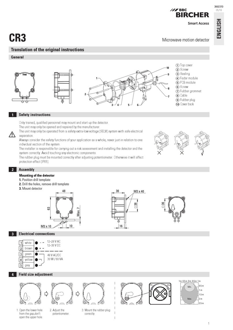
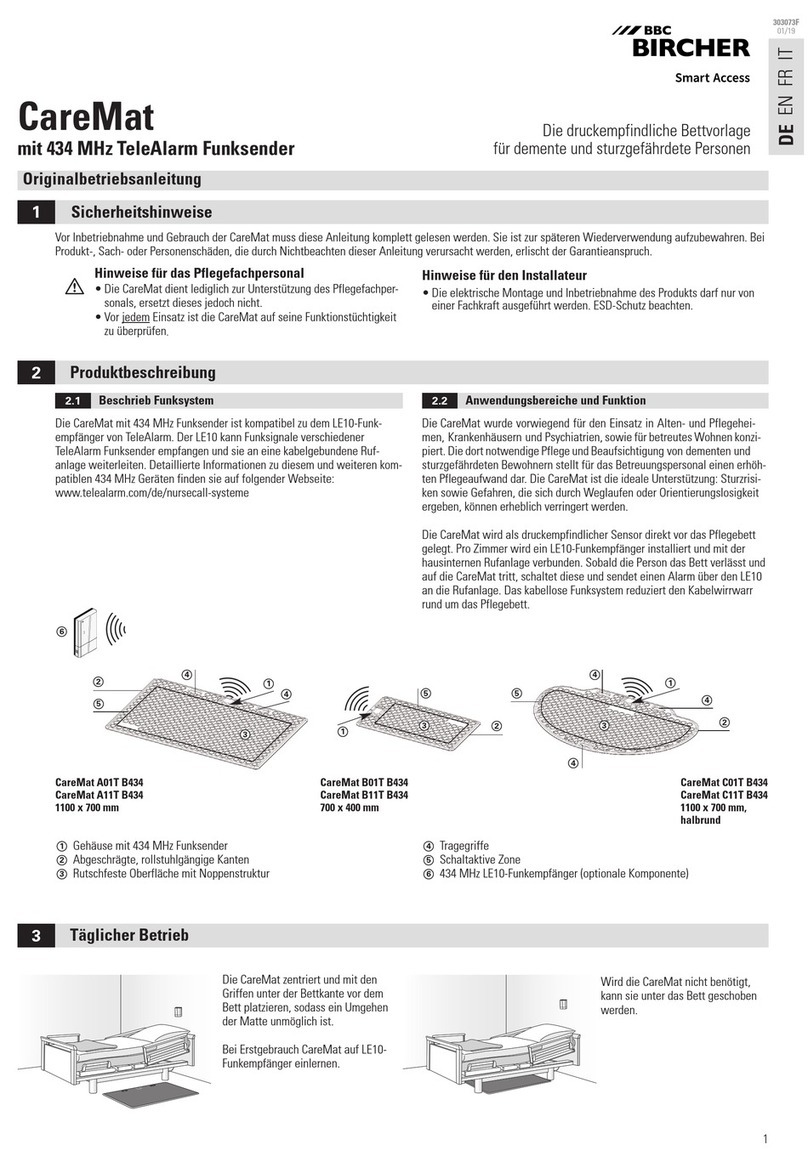
BBC Bircher CareMat User manual

BBC Bircher

BBC Bircher CareMat User manual

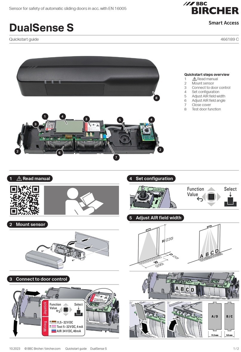
BBC Bircher DualSense S User manual

BBC Bircher

BBC Bircher DualSense S User manual

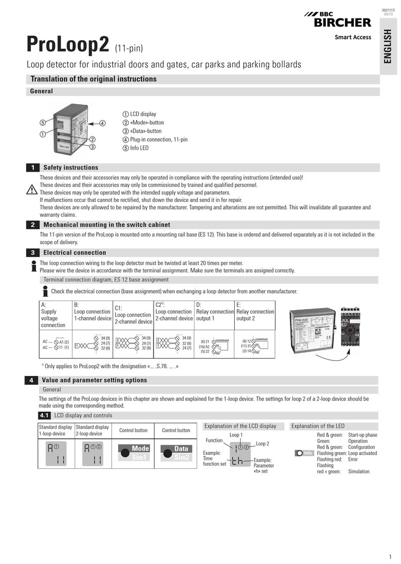
BBC Bircher ProLoop2 User manual

BBC Bircher

BBC Bircher ProLoop2 User manual

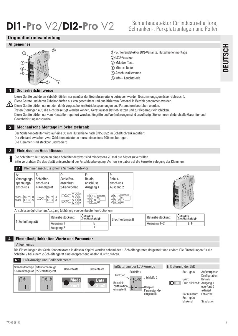
BBC Bircher DI1-Pro V2 User manual

BBC Bircher

BBC Bircher DI1-Pro V2 User manual

BBC Bircher ProLoop Lite 1.S User manual

BBC Bircher

BBC Bircher ProLoop Lite 1.S User manual

BBC Bircher ArtMotion 2 User manual

BBC Bircher

BBC Bircher ArtMotion 2 User manual

BBC Bircher CR3 User manual

BBC Bircher

BBC Bircher CR3 User manual

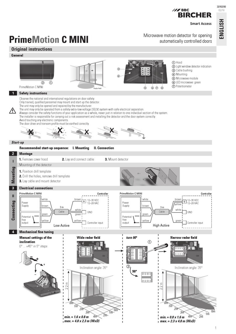
BBC Bircher PrimeMotion C MINI User manual

BBC Bircher

BBC Bircher PrimeMotion C MINI User manual

BBC Bircher TopScan G3 User manual

BBC Bircher

BBC Bircher TopScan G3 User manual
Popular Security Sensor manuals by other brands

Lutron Electronics FC-2601 Operation manual

Lutron Electronics

Lutron Electronics FC-2601 Operation manual

Macurco GD-2A operating instructions

Macurco

Macurco GD-2A operating instructions

Me MERCURY D-45U user manual

Me

Me MERCURY D-45U user manual

Trotec LD6000 operating manual

Trotec

Trotec LD6000 operating manual

Woodpecker WP-632AM instruction manual

Woodpecker

Woodpecker WP-632AM instruction manual

Sperian MILLER 1006320 L General Instructions for Use

Sperian

Sperian MILLER 1006320 L General Instructions for Use

Bosch TriTech installation manual

Bosch

Bosch TriTech installation manual

Dors 60 user manual

Dors

Dors 60 user manual

Etlin-Daniels SENPIR-CM-02 installation manual

Etlin-Daniels

Etlin-Daniels SENPIR-CM-02 installation manual

Bosch DS915 installation instructions

Bosch

Bosch DS915 installation instructions

TanGO TX1 product manual

TanGO

TanGO TX1 product manual

TAG Heuer HL3 Series user manual

TAG Heuer

TAG Heuer HL3 Series user manual

Wiseup WBD100 user guide

Wiseup

Wiseup WBD100 user guide

Satel APMD-150 manual

Satel

Satel APMD-150 manual

North American Rescue Talon 60-0027 Instrcutions for use

North American Rescue

North American Rescue Talon 60-0027 Instrcutions for use

Potter PAD100-RB installation manual

Potter

Potter PAD100-RB installation manual

STEINEL Professional IR Quattro HD-2 COM1 manual

STEINEL

STEINEL Professional IR Quattro HD-2 COM1 manual

General Photonics BPD-002-OEM-400-15 Instructions Note

General Photonics

General Photonics BPD-002-OEM-400-15 Instructions Note

manuals.online logo
manuals.online logoBrands
  • About & Mission
  • Contact us
  • Privacy Policy
  • Terms and Conditions

Copyright 2025 Manuals.Online. All Rights Reserved.