manuals.online logo
Brands
  1. Home
  2. •
  3. Brands
  4. •
  5. MSI
  6. •
  7. Motherboard
  8. •
  9. MSI ATX IR1 User manual

MSI ATX IR1 User manual

CHAPTER 1 INTRODUCTION
1-1
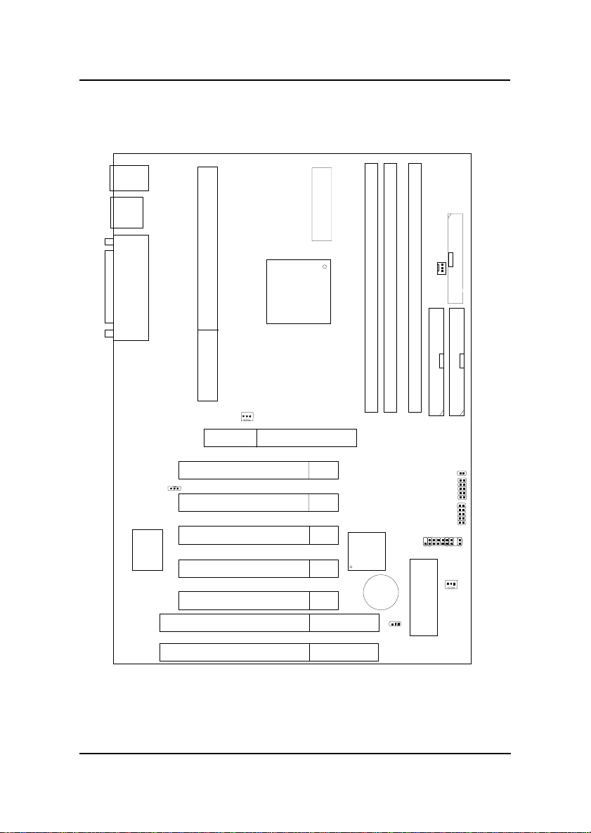
The ATX IR1 mainboard is a high-performance personal computer
mainboard based on the AMD®AthlonTM processor with 3DNOWTM. The
AMD®AthlonTM processor is the newest microprocessor in the AMD K86TM
family of microprocessors.
The mainboard uses the highly integrated AMD®751 system controller and
AMD®756 peripheral controller. The AMD®751 system controller features:
the S2k system interface supports a 100Mhz clock and double-data rate
(DDR) transfers, the 33MHz 32-bit PCI bus interface supports up to five
masters, the 66MHz AGP 1.0 compliant interface supports 2x data transfer
mode, and High Speed memory designed to support a 100MHz SDRAM (PC-
100-compatible-DIMM) with serial presence detect(PSD). The AMD®756
peripheral bus controllers feature an integrated ISA bus controller, an
enhanced IDE controller with Ultra DMA-66 support, and a keyboard/mouse
controller.
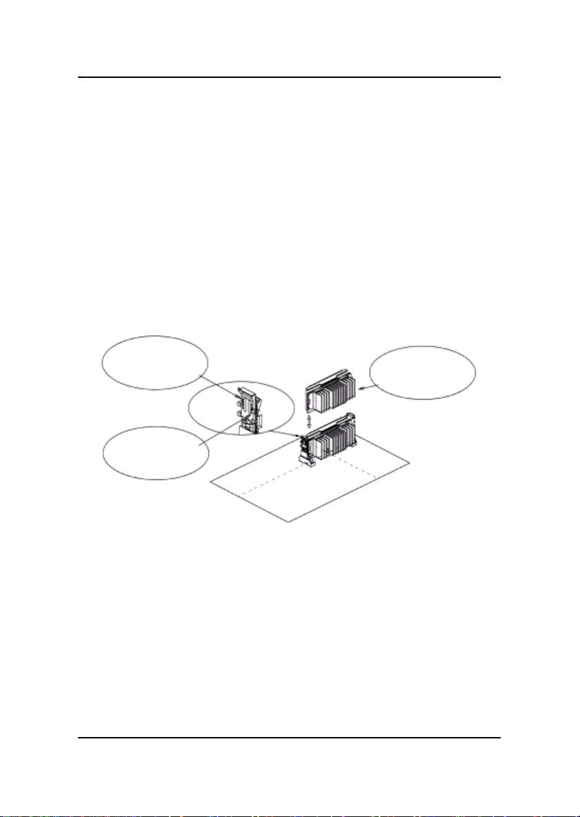
The ATX IR1 mainboard is our first system board to implement the AMD®
750 chipset (AMD®751 and AMD®756), which supports a single Slot A for
AMD®AthlonTM processor.
Chapter 1
INTRODUCTION
CHAPTER 1 INTRODUCTION
1-2
1.1 Mainboard Features
CPU
lSlot A for AMD®AthlonTM processor.
lSupport500MHz,550MHz,600MHz,orhigherprocessor
Chipset
lAMD®IrongateTM chipset. (Northbridge)
-200MHzEV6SystemInterfacespeed
-100MHzSDRAM
-1x/2xAGp
- Status - Silicon currently in bring-up
lAMD®756TM(Viper) chipset. (Southbridge)
-OHCIUSB
-APIC
- ACPI Power Management
FrontSideBus(FSB)
l100MHz clock is supported.
MainMemory
lSupports three memory banks using three 168-pin unbuffered DIMM
sockets.
lSupportsamaximum memory size of768MBforSDRAM.
lSupports 3.3vPC100SDRAMDIMM.
Slots
lOne AGP (Accelerated Graphics Port) slot.
- AGP specification compliant
- AGP66/133MHz 3.3v device support
lFive 32-bit Master PCI Bus slots and two 16-bit ISA bus slots (wherein
one PCI/ISA is shared)
lSupports 3.3v/5v PCI bus Interface.
CHAPTER 1 INTRODUCTION
1-3
On-BoardIDE
lAn IDE controller on the AMD®756TM Viper chipset provides IDE HDD/
CD-ROMwith PIOand Ultra DMA/66 operation modes.
lCan connect up to four IDE devices.
On-BoardPeripherals
lOn-BoardPeripherals include:
-1 floppy port supports 2 FDD with 360K, 720K,1.2M, 1.44M and
2.88Mbytes.
-2 serial ports (COMA + COMB)
- 1 parallel port supports SPP/EPP/ECP mode
- 4 USB ports
- 1 IrDA connector for SIR.
BIOS
lThe mainboard BIOS provides “Plug & Play” BIOS which detects the
peripheral devices and expansion cards of the board automatically.
lThe mainboard provides a Desktop Management Interface(DMI) function
which records your mainboard specifications.
Dimension
lATXForm Factor: 20.9cmx 30.5cm
Mounting
l8 mounting holes.
CHAPTER 1 INTRODUCTION
1-4
1.2 Mainboard Layout
MS-6167 ATX IR1 Mainboard
FDD
IDE2
IDE1
DIMM 1
DIMM 2
DIMM 3
Top: mouse
Top: Port1
USB
Bottom:
Port2
Top: LPT
Bottom:
COMA
COMB
ATX
Power Supply
J9: CPUFAN
PCI SLOT 3
PCI SLOT 2
PCI SlOT 1
SLOT A
AGP Slot
PCI SLOT 4
ISA SLOT 2
BATT
+
BIOS
J6: SYSFAN
AMD-756
chipset JFP1
AMD-751
chipset
JWOL
Bottom:
keyboard
ISA SLOT 1
PCI SLOT 5
USB
Front
Header
IR
Winbond
W83977ATF-AW
J12:
PSFAN
JSLP1
JBAT1
CHAPTER 2 HARDWARE INSTALLATION
2-1
Chapter 2
HARDWARE INSTALLATION
2.1 Central Processing Unit: CPU
Step 1: Install the Retention Mechanism.
Attach the Retention Mechanism to the Mainboard. Push the Plastic
lock to secure the Retention Mechanism into the mainboard.
Secure the processor by
pulling up the Retention
Mechanism Processor
Lock
Insert the processor
like inserting a PCI or
an ISA card
To release the
processor, push the
Retention Mechanism
Processor lock down
Step 2: Install the Processor.
Insert the Processor like inserting a PCI or an ISA card.
Step 3: Lock the Processor.
Lock the processor by pulling up the Retention Mechanism proces-
sor lock shown above.
2.1-1 Processor Installation Procedure
CHAPTER 2 HARDWARE INSTALLATION
2-2
2.1-2 CPU Core Speed Derivation Procedure
The Mainboard can auto-detect the processor speed. Just insert the
AMD Athlon processor into Slot A.
If CPUClock = 100MHz
Core/Bus ratio = 5
then CPU core speed = Host Clock x Core/Busratio
= 100MHz x5
= 500MHz
CHAPTER 2 HARDWARE INSTALLATION
2-3
2.1-4 Fan Power Connectors: J9, J12, & J6
These connectors support system cooling fan with + 12V. It supports three
pin head connector. When connecting the wire to the connector, always
take note that the red wire is the positive and should be connected to the
+12V, the black wire is Ground and should be connected to GND. If your
mainboard has System Hardware Monitor chipset on-board, you must use a
specially designed fan with speed sensor to take advantage of this function.
For fans with fan speed sensor, every rotation of the fan will send out 2
pulses. System Hardware Monitor will count and report the fan rotation
speed.
Note: 1. Always consult vendor for proper CPU cooling fan.
2. CPU FAN supports the FAN control. You can install PC Alert
utility. This will automatically control the CPU FAN Speed according
to the actual CPU temperature.
J9
J9: Processor Fan
J12: Power Supply Fan
J6: System Fan
+12VGND SENSOR
GND
+12V
Sensor
J12
J6
+12VGND SENSOR
CHAPTER 2 HARDWARE INSTALLATION
2-4
2.2 Clear CMOS Jumper: JBAT1
A battery must be used to retain the mainboard configuration in CMOS
RAM. Short 1-2 pins of JBAT1 to store the CMOS data.
Keep Data Clear Data
11
3
3
Note: You can clear CMOS by shorting 2-3 pin, while the system is off.
Then, return to 1-2 pin position. Avoid clearing the CMOS while
the system is on, it will damage the mainboard. Always unplug
the power cord from the wall socket.
22
JBAT1
1
3
CHAPTER 2 HARDWARE INSTALLATION
2-5
2.3 Memory Installation
2.3-1 Memory Bank Configuration
Themainboardsupportsa maximum memory size of 768MB for SDRAM: It
provides three 168-pin unbufferedDIMMs (Double In-Line Memory Mod-
ule) sockets. It supports 8 MB to 256 Mbytes DIMM memory module.
DIMM3(Bank0+Bank1)
DIMM2(Bank2+Bank3)
DIMM1Bank4+Bank5)
CHAPTER 2 HARDWARE INSTALLATION
2-6
A. HowtoinstallaDIMMModule
1. The DIMM slot has 2 Notch Keys “VOLT and DRAM”, so the
DIMM memory module can only fit in one direction.
2. Insert the DIMM memory module vertically into the DIMM slot.
Then push it in.
3. The plastic clip at the side of the DIMM slot will automatically
close.
Single Sided DIMM
Double Sided DIMM
VOLTDRAM
2.3-2 Memory Installation Procedures
CHAPTER 2 HARDWARE INSTALLATION
2-7
1. Supports only PC100 SDRAM DIMM.
2. To operate properly, at least one 168-pin DIMM module must be in-
stalled.
3. This mainboard supports Table Free memory, so memory can be installed
on DIMM1, DIMM 2, or DIMM 3 in any order.
4. Supports 3.3 volt DIMM.
5. The DRAM addressing and the size supported by the mainboard is
shown below:
2.3-3 Memory Population Rules
Table 2.3-1 SDRAM Memory Addressing
16M 1Mx16 ASYM 11 8 8MBx4 16MBx8
2Mx8 ASYM 11 9 16MBx8 32MBx16
64M 2Mx32 ASYM 11 9 32MBx2 64MBx4
2Mx32 ASYM 12 8 16MBx2 32MBx4
4Mx16 ASYM 11 10 32MB 64MB
4Mx16 ASYM 13 8 32MB 64MB
8Mx8 ASYM 13 9 64MB 128MB
64M 2Mx32 ASYM 11 8 16MB 32MB
4Mx16 ASYM 12 8 --- ---
8Mx8 ASYM 12 9 --- ---
DRAM
Tech.
DRAM
Density &
Width
DRAM
Addressing Address Size MB/DIMM
Row Column Single
Side(S) Double
Side(D)
no.
pcs. no.
pcs.
CHAPTER 2 HARDWARE INSTALLATION
2-8
2.4 Case Connector: JFP1
TheKeylock, Power Switch, Reset Switch, Power LED, Speaker, and HDD
LED are all connected to the JFP1 connector block.
JFP1
Power
Switch
Power LED
+
Reset
Switch
HDD
LED
+
Speaker Buzzer
(short
pin)
14
15
Keylock
Dual
Color
LED
Single
Color
LED
CHAPTER 2 HARDWARE INSTALLATION
2-9
2.4-1 Power Switch
Connect to a 2-pin push button switch. This switch has the same feature
withJRMS1.
2.4-2 Reset Switch
Reset switch is used to reboot the system rather than turning the power ON/
OFF. Avoid rebooting while the HDD LED is lit. You can connect the Reset
switch from the system case to this pin.
2.4-3 Power LED
The Power LED is lit while the system power is on. Connect the Power LED
from the system case to this pin. There are two types of LED that you can
use:3-pin single color LED or 2-pin dual color LED(ACPIrequest).
a. 3 pin single color LED connect to pin 4, 5, & 6. This LED will lit
when the system is on.
b. 2 pin dual color LED connect to pin 5 & 6.
GREENColor: Indicate the system is in full on mode.
ORANGEColor: Indicate the system is in suspend mode.
2.4-4 Speaker
Speaker from the system case is connected to this pin.
Ifon-board Buzzer is available:
Shortpin14-15: On-boardBuzzer Enabled.
Openpin14-15: On-board Buzzer Disabled.
2.4-5 HDD LED
HDD LED shows the activity of a hard disk drive. Avoid turning the power
off while the HDD led is lit. You can connect the HDD LED from the system
case to this pin.
2.4-6 Keylock
Keylock allows you to disable the keyboard for security purposes. You can
connect the keylock to this pin.
CHAPTER 2 HARDWARE INSTALLATION
2-10
2.5 Floppy Disk Connector: FDD
The mainboard also provides a standard floppy disk connector FDD that
supports 360K, 720K, 1.2M, 1.44M and 2.88M floppy disk types. This
connector supports the provided floppy drive ribbon cables.
FDD
1
CHAPTER 2 HARDWARE INSTALLATION
2-11
2.6 Hard Disk Connectors: IDE1 & IDE2
The mainboard has a 32-bit Enhanced PCI IDE and Ultra DMA/66 (ICH)/
Ultra DMA/33(ICH0) Controller that provides PIO mode 0~4, Bus Master,
and Ultra DMA/33 function. It has two HDD connectors IDE1 (primary) and
IDE2 (secondary). You can connect up to four hard disk drives, CD-ROM,
120MB Floppy (reserved for future BIOS) and other devices to IDE1 and
IDE2. These connectors support the provided IDE hard disk cable.
IDE1(PrimaryIDEConnector)
The first hard drive should always be connected to IDE1. IDE1 can
connect a Master and a Slave drive. You must configure second hard
drive to Slave mode by setting the jumper accordingly.
IDE2(SecondaryIDEConnector)
IDE2 can also connect a Master and a Slave drive.
Primary IDE Connector
Secondary IDE Connector
11
CHAPTER 2 HARDWARE INSTALLATION
2-12
2.7 Power Supply
2.7-1 ATX 20-pin Power Connector: JPWR1
This connector supports the power button on-board. Using the ATX power
supply, functions such as Modem Ring Wake-Up and Soft Power Off are
supported by this mainboard. This power connector supports instant power
on function which means that system will boot up instantly when the power
connector is inserted on the board.
PIN SIGNAL
11 3.3V
12 -12V
13 GND
14 PS_ON
15 GND
16 GND
17 GND
18 -5V
19 5V
20 5V
PIN SIGNAL
1 3.3V
2 3.3V
3 GND
45V
5 GND
65V
7 GND
8 PW_OK
9 5V_SB
10 12V
PINDEFINITION
Warning: Since the mainboard has the instant power on function, make
sure that all components are installed properly before inserting the power
connector to ensure that no damage will be done.
ATX
Power Connector
11
20
10
1
CHAPTER 2 HARDWARE INSTALLATION
2-13
2.8 IrDA Infrared Module Connector: IR
The mainboard provides one infrared (IR) connector for IR modules. This
connector is for optional wireless transmitting and receiving infrared module.
You must configure the setting through the BIOS setup to use the IR
function.
VCC
NC
IRRX
GND
IRTX
1
IR
CHAPTER 2 HARDWARE INSTALLATION
2-14
2.9 Serial Port Connectors: COM A and COM B
The mainboard provides two 9-pin male DIN connector for serial port COM
A and COM B. These port are 16550A high speed communication port that
send/receive 16 bytes FIFOs. You can attach a mouse or a modem cable
directly into this connector.
PIN SIGNAL
1DCD(Data Carry Detect)
2SIN(Serial In or Receive Data)
3SOUT(Serial Out or Transmit Data)
4DTR(DataTerminal Ready)
5GND
6DSR(Data Set Ready)
7RTS(Request To Send)
8CTS(Clear To Send)
9RI(RingIndicate)
PIN DEFINITION
1 2 3 4 5
6 7 8 9
COM A
Serial Port (9-pin Male)
COM B
CHAPTER 2 HARDWARE INSTALLATION
2-15
2.10 Parallel Port Connector: LPT1
The mainboard provides a 25 pin female centronic connector for LPT. A
parallel port is a standard printer port that also supports Enhanced Parallel
Port(EPP) and Extended capabilities Parallel Port(ECP). See connector and
pin definition below:
PIN SIGNAL PIN SIGNAL
1 STROBE 14 AUTOFEED#
2 DATA0 15 ERR#
3 DATA1 16 INIT#
4 DATA2 17 SLIN#
5 DATA3 18 GND
6 DATA4 19 GND
7 DATA5 20 GND
8 DATA6 21 GND
9 DATA7 22 GND
10 ACK# 23 GND
11 BUSY 24 GND
12 PE 25 GND
13 SELECT
PIN DEFINITION
LPT 1
13
Parallel Port (25-pin Female)
1
25 14
CHAPTER 2 HARDWARE INSTALLATION
2-16
2.11 Mouse Connector: JKBMS1
The mainboard provides a standard PS/2®mouse mini DIN connector for
attaching a PS/2®mouse. You can plug a PS/2®mouse directly into this
connector. The connector location and pin definition are shown below:
2.12 Keyboard Connector: JKBMS1
The mainboard provides a standard PS/2®keyboard mini DIN connector for
attaching a keyboard. You can plug a keyboard cable directly to this
connector.
PS/2 Mouse (6-pin Female)
PS/2 Keyboard (6-pin Female)
Pin1
Mouse DATA
Pin6
NC
Pin2
NC
Pin4
VCC
Pin3
GND
Pin5
Mouse Clock
Pin1
KBD DATA
Pin6
NC
Pin2
NC Pin3
GND
Pin5
KBD Clock
Pin4
VCC

Other MSI Motherboard manuals

MSI MEG X570S UNIFY-X MAX User manual

MSI

MSI MEG X570S UNIFY-X MAX User manual

MSI 785GTM-E45 - Motherboard - Micro ATX User manual

MSI

MSI 785GTM-E45 - Motherboard - Micro ATX User manual

MSI PRO Series User manual

MSI

MSI PRO Series User manual

MSI MS-7666 User manual

MSI

MSI MS-7666 User manual

MSI A88X-G45 GAMING User manual

MSI

MSI A88X-G45 GAMING User manual

MSI MAG X670E TOMAHAWK WIFI User manual

MSI

MSI MAG X670E TOMAHAWK WIFI User manual

MSI Z590 PRO Wi-Fi User manual

MSI

MSI Z590 PRO Wi-Fi User manual

MSI C236M WORKSTATION User manual

MSI

MSI C236M WORKSTATION User manual

MSI MS-6799 User manual

MSI

MSI MS-6799 User manual

MSI PRO B760-P WIFI User manual

MSI

MSI PRO B760-P WIFI User manual

MSI 760GM-P43 Series User manual

MSI

MSI 760GM-P43 Series User manual

MSI MAG B650 TOMAHAWK WIFI User manual

MSI

MSI MAG B650 TOMAHAWK WIFI User manual

MSI MS-6507 User manual

MSI

MSI MS-6507 User manual

MSI X299-A PRO User manual

MSI

MSI X299-A PRO User manual

MSI G45TM-E53 Series User manual

MSI

MSI G45TM-E53 Series User manual

MSI MS-6390 User manual

MSI

MSI MS-6390 User manual

MSI Z87-GD65 GAMING User manual

MSI

MSI Z87-GD65 GAMING User manual

MSI 945GCM5 Series User manual

MSI

MSI 945GCM5 Series User manual

MSI Z390-A PRO User manual

MSI

MSI Z390-A PRO User manual

MSI MEG X570 GODLIKE User manual

MSI

MSI MEG X570 GODLIKE User manual

MSI MS-7298 User manual

MSI

MSI MS-7298 User manual

MSI 970A GAMING PRO CARBON User manual

MSI

MSI 970A GAMING PRO CARBON User manual

MSI MPG Z690 CARBON WIFI User manual

MSI

MSI MPG Z690 CARBON WIFI User manual

MSI MICRO ATX AL12 User manual

MSI

MSI MICRO ATX AL12 User manual

Popular Motherboard manuals by other brands

Asus Prime X670-P manual

Asus

Asus Prime X670-P manual

VMIC VMIVME-1160A product manual

VMIC

VMIC VMIVME-1160A product manual

Supermicro X11SCQ-L user manual

Supermicro

Supermicro X11SCQ-L user manual

ECS H110M4-C3V user guide

ECS

ECS H110M4-C3V user guide

ASROCK QC5000-ITX/WiFi user manual

ASROCK

ASROCK QC5000-ITX/WiFi user manual

IEI Technology eKINO-945GSE user manual

IEI Technology

IEI Technology eKINO-945GSE user manual

TYAN Tempest i5000VS S5372-LC user manual

TYAN

TYAN Tempest i5000VS S5372-LC user manual

Gigabyte MZ71-CE1 user manual

Gigabyte

Gigabyte MZ71-CE1 user manual

Sony BKP-5090 Installation and maintenance manual

Sony

Sony BKP-5090 Installation and maintenance manual

ASROCK Rack EP2C612D16NM installation guide

ASROCK Rack

ASROCK Rack EP2C612D16NM installation guide

IWILL DVD266u-RN manual

IWILL

IWILL DVD266u-RN manual

Asus M4a785t-M - 785G Am3 Max-16Gb Ddr3 Uatx Pcie16 1Pcie... user manual

Asus

Asus M4a785t-M - 785G Am3 Max-16Gb Ddr3 Uatx Pcie16 1Pcie... user manual

Asus M3N-H/HDMI manual

Asus

Asus M3N-H/HDMI manual

Acer AcerPower Flex4000 Series user guide

Acer

Acer AcerPower Flex4000 Series user guide

Espressif Systems ESP8266 Series Hardware Design Guidelines

Espressif Systems

Espressif Systems ESP8266 Series Hardware Design Guidelines

Renesas US082-FS1015EVZ manual

Renesas

Renesas US082-FS1015EVZ manual

RAKwireless RAK4600 quick start guide

RAKwireless

RAKwireless RAK4600 quick start guide

Rohm BD9E202FP4-Z user guide

Rohm

Rohm BD9E202FP4-Z user guide

manuals.online logo
manuals.online logoBrands
  • About & Mission
  • Contact us
  • Privacy Policy
  • Terms and Conditions

Copyright 2025 Manuals.Online. All Rights Reserved.