MiTAC PH14ADI User manual

PH14ADI
Version 1.0
Copyright
Copyright © 2022 MITAC COMPUTING TECHNOLOGY CORPORATION. All rights
reserved. No part of this manual may be reproduced or translated without prior
written consent from MITAC COMPUTING TECHNOLOGY CORPORATION.
Trademark
All registered and unregistered trademarks and company names contained in this
manual are property of their respective owners including, but not limited to the
following.
Intel® is a trademark of Intel® Corporation.
AMI, AMI BIOS are trademarks of AMI Technologies.
Microsoft®, Windows® are trademarks of Microsoft Corporation.
Nuvoton® is a trademark of Nuvoton Technology Corporation.
Notice
Information contained in this document is furnished by MITAC COMPUTING
TECHNOLOGY CORPORATION and has been reviewed for accuracy and reliability
prior to printing. MiTAC assumes no liability whatsoever, and disclaims any express
or implied warranty, relating to sale and/or use of MiTAC products including liability
or warranties relating to fitness for a particular purpose or merchantability. MiTAC
retains the right to make changes to product descriptions and/or specifications at
any time, without notice. In no event will MiTAC be held liable for any direct or
indirect, incidental or consequential damage, loss of use, loss of data or other
malady resulting from errors or inaccuracies of information contained in this
document.

2
Contents
Before you begin… ....................................................................................3
Chapter 1:
Instruction
.................................................................................. 4
1.1 Congratulations..................................................................................4
1.2 Hardware Specifications ....................................................................4
1.3 Software Specifications......................................................................6
Chapter 2: Board
Installation
......................................................................7
2.1 Board Image ......................................................................................8
2.2 Block Diagram....................................................................................9
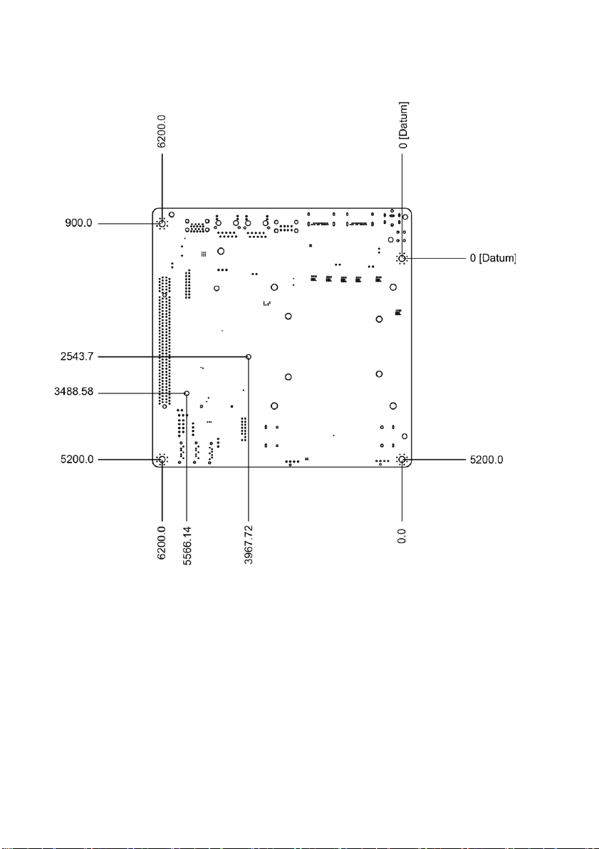
2.3 Mainboard Mechanical Drawing.......................................................10
2.4 Board Parts, Jumpers and Connectors............................................11
2.5 Installing the Processor and Heat sink.............................................23
2.6 Thermal Interface Material...............................................................28
2.7 Tips on Installing Motherboard in Chassis.......................................29
2.8 Installing the Memory.......................................................................31
2.9 Attaching Drive
Cables
.....................................................................34
2.10 Installing Add-In Cards..................................................................... 35
2.11 Connecting External Devices...........................................................36
2.12 Installing the AC/DC
Adaptor
............................................................38
2.13 Finishing Up.....................................................................................38
Chapter 3: BIOS Setup.............................................................................. 39
3.1 About the BIOS................................................................................39
3.2 Main
Menu
........................................................................................41
3.3 Advanced Menu...............................................................................43
3.3 Security............................................................................................ 58
3.4 Boot.................................................................................................. 65
3.5 Save & Exit ......................................................................................67
3.6 Event
Logs
........................................................................................68
Chapter 4: Diagnostics............................................................................. 72
4.1 Flash Utility ...................................................................................... 72
4.2 AMIBIOS Post Code
(Aptio)
.............................................................73
Appendix I: How to recover UEFI BIOS...................................................80
Appendix II: Fan and Temp Sensors.......................................................82

3
Before you begin…
Check the box contents!
The retail motherboard package should contain the following:
1 x PH14ADI Motherboard
1 x SATA Cable
1 x SATA Power Cable
1 x Rear IO Full height Shield
1 x Rear IO half height Shield
IMPORTANT NOTE:
Sales sample may not come with the accessory listed above.
Please contact your sales representative to help order accessory for your
evaluation.

4
Chapter 1: Instruction
1.1 Congratulations
You have purchased the powerful PH14ADI motherboard, based on the Intel®
H610 Chipset. The PH14ADI is designed to support single Intel® 12th Gen. Core
i9/i7/i5/i3 Processor, and up to 64GB of SO-DIMM DDR4 3200 memory.
Leveraging advanced technology from Intel®, the PH14ADI is capable of offering
scalable 32 and 64-bit computing, high-bandwidth memory design, and lightning-
fast PCI-E bus implementation.
The PH14ADI not only empowers you in today’s demanding IT environment but
also offers a smooth path for future application upgradeability. All of these rich
feature sets provides the PH14ADI with the power and flexibility to meet demanding
requirements for today’s IT environments.
Remember to visit the MITACwebsite at https://www.mitacmct.com/. There you
can find all the information on all MITAC products as well as all the supporting
documentation, FAQs, Drivers and BIOS upgrades.
1.2 Hardware Specifications
MITAC PH14ADI
Processor
Q'ty / Socket Type
(1) LGA1700
Supported CPU Series
Intel Core i9/i7/i5/i3 Processors / 12 Gen.
Thermal Design Power
Wattage
Max up to 65W (TDP)
Chipset
PCH
Intel H610
Super I/O
NCT6126D
Memory
Supported DIMM Qty
(2) DIMM slots
DIMM Type / Speed
DDR4 SO-DIMM 3200
Capacity
Up to 64GB
Memory channel
2 Channels per CPU
Memory voltage
1.2V
Expansion
Slots
PCIe
(1) PCIe Gen.4 x16 slot
LAN
Q'ty / Port
(1) GbE + (1) 2.5GbE
Controller
Intel I219-LM (Intel AMT support) / Intel
I225V
Storage
SATA
Connector
(1) SATA-DOM / (2) SATA
Controller
Intel H610
Speed
6Gb/s
Storage
Connector (M.2)
(1) 2280 (by PCIe 4 interface)

5
NVMe
Storage VROC Support
(Optional)
No
Graphic
DisplayPort
Connectortype
(2) Display ports 1.4
Resolution
Up to 4096X2304 @60Hz
Chipset
Intel H610
Input
/Output
USB
(2) USB2.0 ports (via cable) / (2) USB2.0
ports (@ rear) / (2) USB3.2 Gen.1 ports
(via cable) / (2) USB3.2 Gen.2 ports
(@rear)
COM
(2) headers
RJ-
45
(1) GbE port + (1) 2.5GbE port
SATA
(2) SATA-III connectors / (1) SATA-DOM
connectors
Power
DC12V / ATX 4-pin
Displayport
(2) Display ports 1.4
TPM
(Optional)
TPM Support
Please refer to our TPM supported list.
Interface
SPI
System
Monitoring
Chipset
NCT6126D
Fan
Total (2) 4-pin headers
Temperature
Monitors temperature for CPU & system
environment
Voltage
Monitors voltage for CPU, memory, chipset
& power supply
LED
Processor fail LED indicator
AMT Feature
Support Power on/ Power off/ Restart at
remote side
Others
Watchdog timer support
BIOS
Brand / ROM size
AMI / 32MB
Feature
Hardware Monitor / Console Redirection /
User Configurable FAN PWM Duty Cycle /
SMBIOS 3.0/PnP/Wake on LAN / ACPI 6.1
/ ACPI sleeping states S5
Physical
Dimension
Form Factor
Thin Mini-ITX
Board Dimension
6.69" x 6.69" (170 x 170mm)
Regulation
FCC (SDoC)
Class B
CE (DoC)
Class B
Operating
Operating Temp.
0°C ~ 60°C (32°F~ 140°F)
Non-operating Temp.
- 40°C ~ 85°C (-40°F ~ 185°F)
Environment
In/Non-operating
Humidity
90%, non-condensing at 35°C
RoHS RoHS 6/6 Compliant
Yes
Operating
System
OS supported list
Ubuntu 22.04 / Windows® 10 64bit, / Linux
(support by request)

6
Package
Contains
Motherboard
(1) PH14ADI Motherboard
Manual
(1) Quick Installation Guide
I/O Shield
(2) I/O Shield (Full height and Half height)
Cable SATA
(1) SATA power cable / (1) SATA signal
cables
1.3 Software Specifications
For OS (operation system) support, please check with MITAC support for latest
information.

7
Chapter 2: Board Installation
You are now ready to install your motherboard.
How to install our products right… the first time
The first thing you should do is reading this user’s manual. It contains important
information that will make configuration and setup much easier. Here are some
precautions you should take when installing your motherboard:
(1) Ground yourself properly before removing your motherboard from the
antistatic bag. Unplug the power from your computer power supply and then
touch a safely grounded object to release static charge (i.e. power supply
case). For the safest conditions, MITAC recommends wearing a static safety
wrist strap.
(2) Hold the motherboard by its edges and donot touch the bottom of the board,
or flex the board in any way.
(3) Avoid touching the motherboard components, IC chips, connectors, memory
modules, and leads.
(4) Place the motherboard on a grounded antistatic surface or on the antistatic
bag that the board was shipped in.
(5) Inspect the board for damage.
The following pages include details on how to install your motherboard into your
chassis, as well as installing the processor, memory, disk drives and cables.
Caution!
1.
To avoid damaging the motherboard and associated
components, use torque force within the range
5~7
kgf/cm (4.35 ~ 6.09 lb/in)
on each mounting screw for
motherboard installation.
2.
Do not apply power to the board if it has been
damaged.

8
2.1 Board Image
PH14ADI
This picture is representative of the latest board revision available at the time of
publishing. The board you receive may not look exactly like the above picture.

9
2.2 Block Diagram
PH14ADI Block Diagram

10
2.3 Mainboard Mechanical Drawing

11
2.4 Board Parts, Jumpers and Connectors
This diagram is representative of the latest board revision available at the time of
publishing. The board you receive may not look exactly like the above diagram. But
for the DIMM number please refer to the above placement for memory installation.
For the latest board revision, please visit our web site at
https://www.mitacmct.com/.

12
Jumpers & Connectors
Connector
1 USB3.2 Gen1 Header (USB3_HR1)
13 SYS_FAN Header (SYS_FAN1)
2 USB2.0 Header (USB2_HR1)
14 ATX Power INPUT (ATX4P)
3 INTRUDER Header (INTRUD1)
15 DC_12V INPUT (DC12IN1)
4 Front IO_PANEL Header
(FIO_PANEL1)
16 Display port_2 (DP_J2)
5 SATA Header (SATA2)
17 Display port_1 (DP_J1)
6 SATA POWER Header (SATAPWR1)
18 USB2.0 Rear Port (USB2_J1)
7 SATA Header (SATA1)
19 RJ45_2.5G (LAN225_J1)
8 SATA DOM Header (SATADOM1)
20 RTC Battery Header (XBT1)
9 COM1 Header_RS232 (COM1)
21 RJ45_1.0G (LAN219_J1)
10 COM2 Header_RS232 (COM2)
22 USB3.2 Gen2 Rear Port
(USB3_J1)
11 P2398 Card_Header (DEBUG1)
23 TPM Card Header (TPM1)
12 CPU_FAN Header (CPU_FAN1)
Jumpers
Slots
a CMOS Clear Header (CMOS1)
A PCIEX16 Header (PCIEX16_1)
b AT/ATX Select Header (AT1)
B M.2 Key_M Header (M2M)
c PEX8_16 Select Header (PEX8_16)
Jumper Legend
OPEN - Jumper OFF
Without jumper cover
CLOSED - Jumper ON
With jumper cover

13
ATX4P: ATX Power Input Header
Pin
Signal
Pin
Signal
1
GND
2
DC12V_IN
3
GND
4
DC12V_IN
SATADOM1: SATA DOM Header
Pin
Signal
MT1
GND
1
GND
2
TX+
3
TX-
4
GND
5
RX-
6
RX+
7
GND
MT2
VCC
SATA1/SATA2: SATA Header
Pin
Signal
MT1
GND
1
GND
2
TX+
3
TX-
4
GND
5
RX-
6
RX+
7
GND
MT2
GND
M2M: M.2 key-M Header (Slot)
Signal
Pin
Pin
Signal
GND
1
2
3.3V
GND
3
4
3.3V
PERN3
5
6
N/C

14
PERP3
7
8
N/C
GND
9
10
LED
PETN3
11
12
3.3V
PETP3
13
14
3.3V
GND
15
16
3.3V
PERN2
17
18
3.3V
PERP2
19
20
N/C
GND
21
22
N/C
PETN2
23
24
N/C
PETP2
25
26
N/C
GND
27
28
N/C
PERN1
29
30
N/C
PERP1
31
32
N/C
GND
33
34
N/C
PETN1
35
36
N/C
PETP1
37
38
M2_DEVSLP
GND
39
40
N/C
PERN0 / SATA-B+
41
42
N/C
PERP0 / SATA-B-
43
44
N/C
GND
45
46
N/C
PETN0 / SATA-A-
47
48
N/C
PETP0 / SATA-A+
49
50
M2_PERST#
GND
51
52
CLKREQ5#
PE_CLK_N
53
54
M2_PE WAKE#
PE_CLK_P
55
56
N/C
GND
57
58
N/C
59
60
61
62

15
63
64
65
66
NC
67
68
SUSCLK
PEDER_OC-PCIE/GND-SATA
69
70
3.3V
GND
71
72
3.3V
GND
73
74
3.3V
GND
75
PCIEX16_1: PCIEX16 Header (Slot)
Signal
Pin
Pin
Signal
12V
B1
A1
PRSNT1#
12V
B2
A2
12V
12V
B3
A3
12V
GND
B4
A4
GND
SMCLK
B5
A5
JTAG2
SMDAT
B6
A6
JTAG3
GND
B7
A7
JTAG4
3V3
B8
A8
JTAG5
JTAG1
B9
A9
3V3
V3AUX
B10
A10
3V3
WAKE#
B11
A11
PERST#
RSVD_1
B12
A12
GND
GND
B13
A13
REFCLK+
PETp0
B14
A14
REFCLK-
PETn0
B15
A15
GND

16
GND
B16
A16
PERp0
PRSNT2#
B17
A17
PERn0
GND
B18
A18
GND
PETp1
B19
A19
RSVD_4
PETn1
B20
A20
GND
GND
B21
A21
PERp1
GND
B22
A22
PERn1
PETp2
B23
A23
GND
PETn2
B24
A24
GND
GND
B25
A25
PERp2
GND
B26
A26
PERn2
PETp3
B27
A27
GND
PETn3
B28
A28
GND
GND
B29
A29
PERp3
RSVD_2
B30
A30
PERn3
PRSNT2#_2
B31
A31
GND
GND
B32
A32
RSVD_5
PETp4
B33
A33
RSVD_6
PETn4
B34
A34
GND
GND
B35
A35
PERp4
GND
B36
A36
PERn4
PETp5
B37
A37
GND
PETn5
B38
A38
GND
GND
B39
A39
PERp5
GND
B40
A40
PERn5
PETp6
B41
A41
GND

17
PETn6
B42
A42
GND
GND
B43
A43
PERp6
GND
B44
A44
PERn6
PETp7
B45
A45
GND
PETn7
B46
A46
GND
GND
B47
A47
PERp7
PRSNT2#_3
B48
A48
PERn7
GND
B49
A49
GND
PETp8
B50
A50
RSVD_7
PETn8
B51
A51
GND
GND
B52
A52
PERp8
GND
B53
A53
PERn8
PETp9
B54
A54
GND
PETn9
B55
A55
GND
GND
B56
A56
PERp9
GND
B57
A57
PERn9
PETp10
B58
A58
GND
PETn10
B59
A59
GND
GND
B60
A60
PERp10
GND
B61
A61
PERn10
PETp11
B62
A62
GND
PETn11
B63
A63
GND
GND
B64
A64
PERp11
GND
B65
A65
PERn11
PETp12
B66
A66
GND
PETn12
B67
A67
GND
GND
B68
A68
PERp12

18
GND
B69
A69
PERn12
PETp13
B70
A70
GND
PETn13
B71
A71
GND
GND
B72
A72
PERp13
GND
B73
A73
PERn13
PETp14
B74
A74
GND
PETn14
B75
A75
GND
GND
B76
A76
PERp14
GND
B77
A77
PERn14
PETp15
B78
A78
GND
PETn15
B79
A79
GND
GND
B80
A80
PERp15
PRSNT2#_4
B81
A81
PERn15
RSVD_3
B82
A82
GND
TPM1: TPM Card Header
Signal
Pin
Pin
Signal
SPI_CLK
1
7
3VSB
PLTRST_N
2
8
TPM_DET
SPI_MOSI
3
9
TPM_PIRQ_N
SPI_MISO
4
10
VCC3_TPM
SPI_CS2_N
5
11
GND
NC
6
SYS_FAN1/CPU_FAN1: System FAN Header, CPU FAN Header
Pin
Signal
1
GND
2
12V
3
FAN TACH
4
FAN Control (PWM)

19
COM1/COM2: RS-232 COM Port Header
Signal
Pin
Pin
Signal
DCD (Data Carrier Detect)
1
2
RXD# (Receive Data)
TXD# (Transmit Data)
3
4
DTR (Data Terminal
Ready)
GND
5
6
DSR (Data Set Ready)
RTS (Request To Send)
7
8
CTS (Clear To Send)
RI (Ring Indicator)
9
10
Key (no pin)
DEBUG1: P2398 Card Header
Signal Name
Pin
Pin
Signal Name
GND
1
2
VCC (5V)
Power Button
3
X
KEY
PORT80_A
5
6
3VSB
PORT80_B
7
8
PORT80_E
PORT80_C
9
10
PORT80_F
PORT80_D
11
12
PORT80_G
PORT80_DGH
13
14
PORT80_DGL
Dip switch_GPIO42
15
16
Dip switch_GPIO43
AT1: AT/ATX Mode Selection Header
The Jumper setting is to select Normal power
button on, or always power on while DC-IN.
Pin
Signal Name
1
AT1_RSMRST
2
AT1_PWRBT_N
3
NC
Pins 1&2: jumper position for AT mode (always power on)
Pins 2&3: jumper position for Normal mode (Default)

20
SATAPWR1: SATA POWER Header
Pin
Signal Name
1
12V
2
GND
3
GND
4
VCC(5V)
FIO_PANEL1: Front IO Panel Header
Pin
Signal
Description
Pin
Signal
Description
1
HDD_POWER_LED
Pull-up resistor (510Ω) to
+5V
2
POWER_LED_MAIN
[Out] Front panel LED
(main color)
3
HDD_LED#
[Out] Hard disk activity
LED
4
POWER_LED_ALT
[Out] Front panel LED
(alt color)
5
GROUND
Ground
6
POWER_SWITCH#
[In] Power switch
7
RESET_SWITCH#
[In] Reset switch
8
GROUND
Ground
9
VCC(+5V)
Power
10
KEY
No pin
XBT1: RTC Battery Header
Pin
Signal Name
1
Battery Anode
2
GND
INTRUD1: INTRUDER Header
Pin
Signal
1
INTRUDER_N
3
GND
Table of contents
Other MiTAC Motherboard manuals

MiTAC
MiTAC PH11SI User manual

MiTAC
MiTAC 6515WU User manual

MiTAC
MiTAC TYAN S5555 Series User manual

MiTAC
MiTAC PH10LU User manual

MiTAC
MiTAC PD10TI User manual

MiTAC
MiTAC 6513VX Service manual

MiTAC
MiTAC TYAN S7103 User manual

MiTAC
MiTAC TYAN S5557 User manual

MiTAC
MiTAC PD10BI User manual

MiTAC
MiTAC TYAN S5539 User manual

MiTAC
MiTAC TYAN S5565 User manual

MiTAC
MiTAC Tyan S5542 User manual

MiTAC
MiTAC TYAN S5545 User manual

MiTAC
MiTAC PD10AI User manual

MiTAC
MiTAC 5114VU Service manual

MiTAC
MiTAC PH10CMU User manual

MiTAC
MiTAC 6010Eu/va Service manual

MiTAC
MiTAC PD11KS User manual

MiTAC
MiTAC TYAN S5502 User manual

MiTAC
MiTAC 8575 User manual