BCM MX56N User manual

MX56N
AMD G-Series APU with A55E Controller Hub (FCH) Mini ITX Motherboard
User’s Manual Ver. 1.0
BCM Advanced Research, An Industrial Leader Since 1990 in Industrial Motherboards & Systems
11 Chrysler, Irvine, CA 92618 USA | www.bcmcom.com | (PH)949.470.1888 | (FAX)949.470.0971
For Tech Support, please visit www.bcmcom.com/bcm_support_legacyProductSupport.htm or contact
BCMTechSupport@bcmcom.com

Contents
FCC Statement ......................................................................................................................3
Notice.....................................................................................................................................3
Copyright Notice ....................................................................................................................3
Trademark Acknowledgement...............................................................................................3
Disclaimer ..............................................................................................................................3
Life Support Policy.................................................................................................................4
BCM Customer Services........................................................................................................4
Product Warranty...................................................................................................................5
Manual Objectives .................................................................................................................5
Safety Precautions.................................................................................................................5
Document Amendment History..............................................................................................6
Chapter 1 .............................................................................................................................14
1.1 Before you Proceed ..................................................................................................15
1.2 Motherboard Overview..............................................................................................16
1.2.1 Placement Direction..................................................................................................................... 16
1.2.2 Screw Holes ................................................................................................................................ 16
1.3 Motherboard Layout..................................................................................................17
1.4 Central Processing Unit (CPU).................................................................................19
1.5 System Memory........................................................................................................21
1.6 Expansion Slots ........................................................................................................24
1.7 Jumpers ....................................................................................................................26
1.8 Connectors................................................................................................................28
Chapter 2 .............................................................................................................................39
2.1 BIOS Setup Program................................................................................................40
2.1.1 Legend Box ................................................................................................................................. 41
2.1.2 List Box........................................................................................................................................ 41
2.1.3 Sub-menu.................................................................................................................................... 41
2.2 BIOS Menu Screen...................................................................................................42
Save Changes and Exit .......................................................................................................61
Discard Changes and Exit ...................................................................................................61
Restore Defaults ..................................................................................................................61

FCC Statement
THIS DEVICE SUPPORTS PART 15 FCC RULES. OPERATION IS SUBJECT TO THE
FOLLOWING TWO CONDITIONS:
(1) THIS DEVICE MAY NOT CAUSE HARMFUL INTERFERENCE.
(2) THIS DEVICE MUST ACCEPT ANY INTERFERENCE RECEIVED INCLUDING
INTERFERENCE THAT MAY CAUSE UNDESIRED OPERATION.
THIS EQUIPMENT HAS BEEN TESTED AND FOUND TO COMPLY WITH THE LIMITS FOR A CLASS "A"
DIGITAL DEVICE, PURSUANT TO PART 15 OF THE FCC RULES.
THESE LIMITS ARE DESIGNED TO PROVIDE REASONABLE PROTECTION AGAINST HARMFUL
INTERFERENCE WHEN THE EQUIPMENT IS OPERATED IN A COMMERCIAL ENVIRONMENT. THIS
EQUIPMENT GENERATES, USES, AND CAN RADIATE RADIO FREQUENCY ENERGY AND, IF NOT
INSTATLLED AND USED IN ACCORDANCE WITH THE INSTRUCTION MANUAL, MAY CAUSE HARMFUL
INTERFERENCE TO RADIO COMMUNICATIONS.
OPERATION OF THIS EQUIPMENT IN A RESIDENTIAL AREA IS LIKELY TO CAUSE HARMFUL
INTERFERENCE IN WHICH CASE THE USER WILL BE REQUIRED TO CORRECT THE INTERFERENCE
AT HIS OWN EXPENSE.
Notice
This guide is designed for experienced users to setup the system within the shortest time.
For detailed information, please always refer to the electronic user's manual.
Copyright Notice
Copyright © 2010 BCM Advanced Research, ALL RIGHTS RESERVED.
No part of this document may be reproduced, copied, translated, or transmitted in any form or by any means,
electronic or mechanical, for any purpose, without the prior written permission of the original manufacturer.
Trademark Acknowledgement
Brand and product names are trademarks or registered trademarks of their respective owners.
Intel®and Pentium®are registered trademarks of Intel Corporation.
AMD, Athlon™, Athlon™ XP, Thoroughbred™, and Duron™ are registered trademarks of AMD
Corporation.
NVIDIA, the NVIDIA logo, DualNet, and nForce are registered trademarks or trade-marks of NVIDIA
Corporation in the United States and/or other countries.
PS/2 and OS®are registered trademarks of International Business Machines Corporation.
Windows®98/2000/NT/XP/Vista are registered trademarks of Microsoft Corporation.
Netware®is a registered trademark of Novell, Inc.
Award®is a registered trademark of Phoenix Technologies Ltd.
AMI®is a registered trademark of American Megatrends Inc.
Disclaimer
BCM Advanced Research reserves the right to make changes, without notice, to any product, including
circuits and/or software described or contained in this manual in order to improve design and/or performance.

BCM Advanced Research assumes no responsibility or liability for the use of the described product(s),
conveys no license or title under any patent, copyright, or masks work rights to these products, and makes no
representations or warranties that these products are free from patent, copyright, or mask work right
infringement, unless otherwise specified. Applications that are described in this manual are for illustration
purposes only. BCM Advanced Research makes no representation or warranty that such application will be
suitable for the specified use without further testing or modification.
Life Support Policy
BCM Advanced Research PRODUCTS ARE NOT FOR USE AS CRITICAL COMPONENTS IN LIFE
SUPPORT DEVICES OR SYSTEMS WITHOUT THE PRIOR WRITTEN APPROVAL OF BCM Advanced
Research.
As used herein:
1. Life support devices or systems are devices or systems which, (a) are intended for surgical implant into
body, or (b) support or sustain life and whose failure to perform, when properly used in accordance with
instructions for use provided in the labeling, can be reasonably expected to result in significant injury to the
user.
2. A critical component is any component of a life support device or system whose failure to perform can be
reasonably expected to cause the failure of the life support device or system, or to affect its safety or
effectiveness.
BCM Customer Services
Each and every BCM product is built to the most exacting specifications to ensure reliable performance in the
harsh and demanding conditions typical of industrial environments. Whether your new BCM device is
destined for the laboratory or the factory floor, you can be assured that your product will provide the reliability
and ease of operation for which the name BCM has come to be known.
Your satisfaction is our primary concern. Here is a guide to BCM customer services. To ensure you get the full
benefit of our services, please follow the instructions below carefully.
We want you to get the maximum performance from your products. So if you run into technical difficulties, we
are here to help. For the most frequently asked questions, you can easily find answers in your product
documentation. These answers are normally a lot more detailed than the ones we can give over the phone.
So please consult the user’s manual first.
To receive the latest version of the user’s manual; please visit our Web site at www.bcmcom.com.
If you still cannot find the answer, gather all the information or questions that apply to your problem, and with
the product close at hand, call your dealer. Our dealers are well trained and ready to give you the support you
need to get the most from your BCM products. In fact, most problems reported are minor and are able to be
easily solved over the phone.
In addition, free technical support is available from BCM engineers every business day. We are always ready
to give advice on application requirements or specific information on the installation and operation of any of
our products. Please do not hesitate to call or e-mail us.
BCM Advanced Research
11 Chrysler
Irvine, CA, 92618 USA
Phone: +1-949-470-1888
Fax: +1-949-470-0971
Website: www.bcmcom.com
E-mail: [email protected]

Product Warranty
BCM warrants to you, the original purchaser, that each of its products will be free from defects in materials
and workmanship for two years from the date of purchase.
This warranty does not apply to any products which have been repaired or altered by persons other than
repair personnel authorized by BCM, or which have been to misuse, abuse, accident or improper installation.
BCM assumes no liability under the terms of this warranty as a consequence of such events.
Because of BCM high quality-control standards and rigorous testing, most of our customers never need to
use our repair service. If any of BCM products is defective, it will be repaired or replaced at no charge during
the warranty period. For out-of-warranty repairs, you will be billed according to the cost of replacement
materials, service time, and freight. Please consult your dealer for more details. If you think you have a
defective product, follow these steps:
1. Collect all the information about the problem encountered. (For example, CPU type and speed, BCM
products model name, hardware & BIOS revision number, other hardware and software used, etc.)
Note anything abnormal and list any on-screen messages you get when the problem occurs.
2. Call your dealer and describe the problem. Please have your manual, product, and any helpful
information available.
3. If your product is diagnosed as defective, obtain an RMA (return material authorization) number from
your dealer. This allows us to process your good return more quickly.
4. Carefully pack the defective product, a complete Repair and Replacement Order Card and a
photocopy proof of purchase date (such as your sales receipt) in a shippable container. A product
returned without proof of the purchase date is not eligible for warranty service.
Write the RMA number visibly on the outside of the package and ship it prepaid to your dealer.
Manual Objectives
This manual describes in detail the BCM MX510D Mini ITX motherboard.
We strongly recommend that you study this manual carefully before attempting to interface with RX45Q or
change the standard configurations. Whilst all the necessary information is available in this manual we would
recommend that unless you are confident, you contact your supplier for guidance.
Please be aware that it is possible to create configurations within the CMOS RAM that make booting
impossible. If this should happen, clear the CMOS settings, (see the description of the Jumper Settings for
details).
If you have any suggestions or find any errors concerning this manual and want to inform us of these, please
contact our Customer Service department with the relevant details.
Safety Precautions
Always completely disconnect the power cord from your chassis whenever you work
with the hardware. Do not make connections while the power is on. Sensitive
electronic components can be damaged by sudden power surges. Only experienced
electronics personnel should open the PC chassis.
Always ground yourself to remove any static charge before touching the motherboard.
Modern electronic devices are very sensitive to static electric charges. As a safety

precaution, use a grounding wrist strap at all times. Place all electronic components in
a static-dissipative surface or static-shielded bag when they are not in the chassis.
Document Amendment History
Revision Revision History Date
V 1.0 First release for PCB 1.1 2011/05/10

Specifications Summary
APUG‐Series
APUType
AMDG‐SeriesT56N1.6GHzDC/T48N1.4GHzDC/T40N1.0GHz
DC/T40E1.0GHzDC(Optional)/T44R1.2GHzSC/T40R1.0GHz
SC(Optional)
ProcessorFamilyAMDG‐Series
LongLifeProcessorListTDP5~18W,Tshutdown125℃
PackageFT1(BGA)413ballsp=0.8mm,19x19mm
L2CacheL1:32KB+32KBpercore,L2:512KBcachepercore
UMI4‐Lane(x4)PCIegen2
PowerManagementC6supported
PCIE4‐Lane(x4)PCIegen2
CPUProcess40nm
Memory
SystemMemory
MemoryTypeOneDDR31066SODIMM
DIMM#1xSODIMM204Pin/SingleChannel
Max.Capacity 4GB
Chipset
FCH
FusionControllerHubAMDA55EControllerHub(Hudson‐E1)
PCIex4Gen2
USB8USB2.0(4Rear,4Internal)
SMBusYes
LPCYes
SATA5SATA3.0(OnesupportSATADOM)
HDAudiosupport4channel,PowerSaving,4codec
ClockGen.Integrated
PackageFCBGA23x23mm,605balls
EnvironmentTDP2.7~5.7W,Tcase105℃
Display
IntegratedGraphicController
AMDRadeonHD6320(T56N)/AMDRadeonHD
6310(T48N)/AMDRadeonHD6290(T40N)/AMDRadeonHD
6250(T40E/T44R/T40R)
HWdecoder/3DfeatureDirectX11,OpenGL4.0,dedicatedHW(UVD3.0)forH.264,VC‐1,
MPEG‐2,DivXdecode

LVDS1,18bpp(SinglelinkLVDSupto1400x1050)
VGAT56N/T48N(18W)supportsupto2560x1600
T40N/T44R(9W)supportsupto1920x1200
HDMI1supportHDMI1.3a&1080pupto1920x1080
DualDisplayVGA+LVDS,VGA+HDMI,HDMI+LVDS
GigabitEthernet
ChipsetLAN1RTL8111DLGigabitLAN
LAN2RTL8111DLGigabitLAN
Left:Link(Off)/Active(FlashYellow)
LANLED
Right:1Gbps(Green)/100Mbps(Orange)/10Mbps(Off)
DisableLANthroughBIOSYes
WOLYes
BootfromLANYes
ASFN/A
Audio
Codec7.1ChannelHDAudio
ChipsetRealtekALC892
AudiooutputheaderYes,FrontAudioPinHeader
FrontIOConnectorStackPhoneJack(MicIn,Line‐out,Line‐in)
SPDI/FYes
AmplifierTITPA3005
RS232COM
LPCtoCOM2COMforRearI/OD‐Sub
2COMwithheaders
SuperI/O
ChipsetWinbondW83627DHG‐P
Fanspeedmonitor&controlFANSpeedControlbyThermalSensor
TemperatureYes
Voltage+3.3V,+5V,5Vsb,+12V,‐12V
Buzzer
OnboardbuzzerYes
WDT
WatchdogTimerProgrammable1~255sec/min
TPM
TPMOnboardTPM1.1/1.2ByInfineonSLB9635(Optional)

BIOS
BIOSCore
BIOSCoreAMIEFI
BIOSFlash
BIOSFlash16MbSPI
SWRAID
SWRAIDNone
BootupDevice
SerialATA Yes(CFast)
IDEdeviceN/A
USBdeviceYes
BootfromLANYes
PowerManagement
ACPIACPI3.0
APMNA
SleepStateS3,S4,S5
OtherFeature
PCHealthYES
CMOSbackupBIOSCMOSautomaticbackupandrestoresetupdata
SmartFANCPU,SYSFAN,SmartFanIII+
GraphicsmemorymodeSharedMemoryupto2GB
PowerPlay380,200MHz,configurePowerto2.7~5.7W
SATASupportSATAIII(6Gbps)
InternalConnector
DebugPort
CPUHDTheader
SPI1
Display
LVDS1
eDP1,(optional)
Inverter
LVDSINV3.3V
Audio
FrontPanel1
Amplifier1
SPDI/F1
USB
USB4

Serial
COM2
IDE
IDENA
SATA
SATA 5(SATAIII6Gb/s)
SATApowerNA
Fanconnector
Systemfanconnector1systemfan(3pinforsystemwithsmartfancontrol)
CPUfanconnector1CPUfan(3pinforsystemwithsmartfancontrol)
GPIO
General8bit
FrontI/O
Display
HDMI1
VGA1,co‐layoutwithheader
DVINA
Ethernet
RJ‐452,stackwithUSB
USB
USB4(USB2.0port)
COM
Serialport2*RS‐232
PS/2
KB/MS2,co‐laysingleDIN
Audio
PhoneJack
1Line‐in
1Line‐out
1MIC
co‐lay1jackconnector
Power
PowerConnector
PowerTypeAT/ATX
PowerRequirement+3.3V,+5V,+12V,‐12V,5Vsb
LEDIndicator
LED
HDDStatus4;alive,green;dead,red
4;access,flashyellow

PoweronrearIO1;Blue
ExpansionSlot
ExpansionSlot
Mini‐PCIExpress1
PCIex41
PCBPhysicalFeature
Dimension170x170mm
Layer6Layer
PowerConsumption<45W
OperatingTemperature0℃‐60℃
HeatSinkCoolerFAN
StorageTemperature‐20℃~80℃
Vibration(nonOP)3.0Grms,heatsinkbackplaneTBD
PCBPrinting
ModelnameinsilkscreenNone
RevisioninsilkscreenNo
PCBColorBlue
CEmarkonPCBYes
WEEEYes
BCMPCBpartnumberYes
VersionNo
FCCmarkonPCBYes
Cert.Compliance
CEPre‐scanforClassB,EN‐55022/24
FCCPre‐scanforFCCPART15,ClassB
IEC‐60601 compliance
Accessory
AccessoryList
FP_USBcableNone
SATAcableKit1dataand1power
SerialPort2
I/OShield1
DriverCD1
StartupManual1
FP_Powerbutton,powerLED,HDD
LEDkitNone

AVL
OSSupportListWindowsXPSP3,Windows7Pro,LinuxFedora14

Block Diagram

Chapter 1
This chapter describes the motherboard features and the new technologies it supports.
Product Introduction

Production Introduction
1.1 Before you Proceed
Take note of the following precautions before you install motherboard components or
change any motherboard settings.
Unplug the power cord from the wall socket before touching any
component.
Use a grounded wrist strap or touch a safely grounded object or a
metal object, such as the power supply case, before handling
components to avoid damaging them due to static electricity
Hold components by the edges to avoid touching the ICs on
them.
Whenever you uninstall any component, place it on a grounded
antistatic pad or in the bag that came with the component.
Before you install or remove any component, ensure that the ATX
power supply is switched off or the power cord is detached from
the power supply. Failure to do so may cause severe damage to
the motherboard, peripherals, and/or components.

1.2 Motherboard Overview
Before you install the motherboard, study the configuration of your chassis to ensure that
the motherboard fits into it. Refer to the chassis documentation before installing the
motherboard.
Make sure to unplug the power cord before installing or removing the
motherboard. Failure to do so can cause you physical injury and
damage motherboard components.
1.2.1 Placement Direction
When installing the motherboard, make sure that you place it into the chassis in the correct
orientation. The edge with external ports goes to the rear part of the chassis as indicated in
the image below.
1.2.2 Screw Holes
Place four (4) screws into the holes indicated by circles to secure the motherboard to the
chassis.
Do not over tighten the screws! Doing so can damage the
motherboard.
Place this side towards the rear of the
chassis

1.3 Motherboard Layout

Layout Content List
Slots
Label Function Note
CFast Compact Flash socket Rear side
MINI_PCIE Mini PCI-E slot 52PIN
PCIE PCI Eslot 64PIN
SODIMM_A1 204-PIN SODIMM slot 1 204-PIN
Jumpers
Label Function Note
CLRTC Clear CMOS 3 x 1 header, pitch 2.54mm
JCOMPWR1 COM1 RI/+5V/+12V Selection 3 x 2 header, pitch 2.0mm
JCOMPWR2 COM2 RI/+5V/+12V Selection 3 x 2 header, pitch 2.0mm
Rear IO
Label Function Note
KBMS PS/2 keyboard and mouse 6-pin Mini-Din
COM12 Serial Port Connector D-sub 9-pin, male
VGA_DVI VGA Connector D-sub 15-pin, female
USB3,4,5,6 USB Connector x 4 2 x 5 Header, pitch 2.54mm
LAN1,2 RJ-45 Ethernet Connector x 2
AUDIO Line-in Port, Line-out Port,
Microphone Port, 7.1 Channel Audio I/O (3 jacks)

1.4 Central Processing Unit (CPU)
1.4.1 Connect the CPU Fan cable to the CPU_FAN connector on the motherboard.
Do not forget to connect the CPU Fan connector! Hardware monitoring errors can occur if
you fail to plug this connector.
After installation, make sure to plug-in the ATX power cable to the
motherboard.
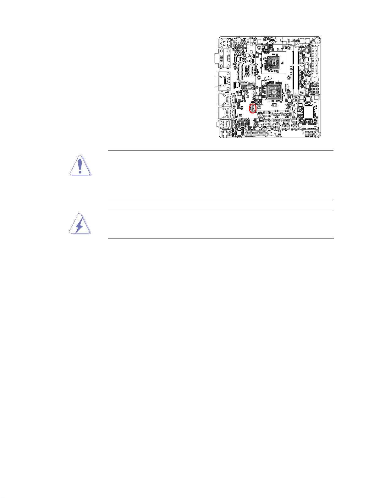
1.4.2 Connect the CPU fan cable to the
CPU_FAN connector on the
motherboard.
Do not forget to connect the fan cables to the fan connectors.
Insufficient air flow inside the system may damage the
motherboard components, and hardware monitoring errors can
occur if you fail to plug this connector.
These are not jumpers! DO NOT place jumper caps on the fan
connectors.
After installation, make sure to plug-in the ATX power cable to the
motherboard.
Other manuals for MX56N
1
Table of contents
Other BCM Motherboard manuals


