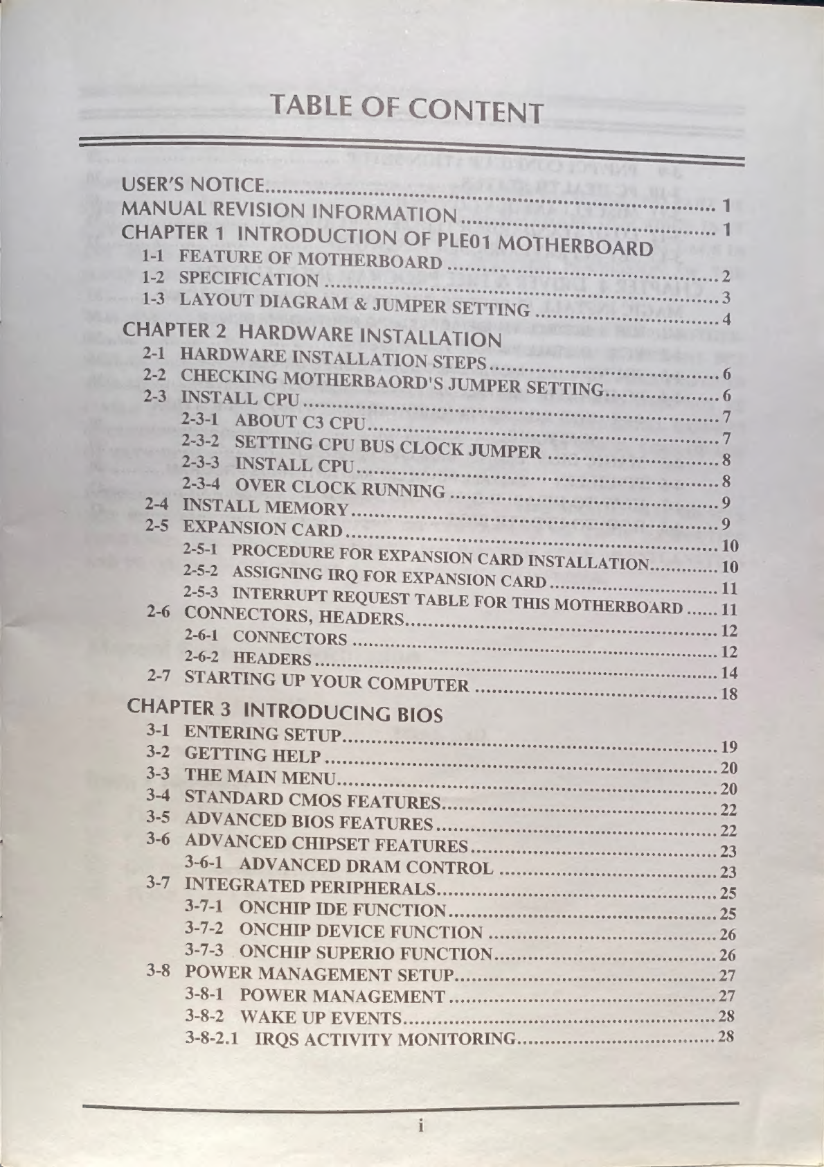
JETWAY PLE01 User manual

_
PLEO!
USER'S
MANUAL

@
Trademark:
_
™
”
rademar
a
*
Specifications
and
Information
contained
in
this
documentation
are
furnished
for
information
use
only,
and
are
subject
to
change
at
any
time
without
notice,
and
should
not
be
construed
as
a
commitment
by
manufacturer.

TABLE
OF
CONTENT
+
USER’S
NOTICE
Sin
we
MOR
CS
OCR
eS
CESS
CU
eRaeseeescenesece
ssasseraresracttacaceties
ith
PAD
1
Dre
aeccy
SON
INEQRMATION.
coer
aaa
iain
dis
os
1
CHAPTER
1
INTRODUCTION
OF
PLEO1
MOTHERBOARD
Rete
MOTHERBOARD...
7h,
CR
Ol
2
DOME
ee
arn
incrersetereitete
eee
Ie
&
STORE
©
3
Boe,
LAGRAM
&
SUMPER
SETTING...)
Nf00
Sead
4
CHAPTER
2
HARDWARE
INSTALLATION
Ree
AEE
INSTALLATION
STEPS
1.12...
eee
6
5,
CHECKING
MOTHERBAORD'S
JUMPER
SETTING...
6
MM
as
CEU
sseesent
crete
stay
iestegusnseerrecrsso
ee
eT
Fi
“SELON
O
4
IR
MR
Eig
7
52.
SETTING-CPU
BUS
CLOCK
JUMPER
........
cn
8
IOP
rovcssreeessosensanits
ra..ccen
ghey
8
Been’
2
CLOCKRUNNING
5c...5c0:-sssssiag
ort
eee
9
Ree
MEMORY...
nec
cdo
a
ee
9
ee
SON
CARD
oe
ereeeessccsiaee
nt
ne
10
2-5-1
PROCEDURE
FOR
EXPANSION
CARD
INSTALLATION.............
10
Bi
~LSIGNING
TRO
FOR
EXPANSION
CARD
tian
ot
u
2-5-3.
INTERRUPT
REQUEST
TABLE
FOR
THIS
MOTHERBOARD
......
11
eee
2
SECTORS,
HEADERS...
0s,
12
RECTORS
csscnnss
conse.
tite
a
ee
12
Fee
TA
DER
S
tert.
ot
ttt.
n3.
igi
cds
ee
14
ge
SLR
TING
UP
YOUR
COMPUTER
«..:..0.<..
18
CHAPTER
3
INTRODUCING
BIOS
Ba
te
NURING
SETUP......;.
Dee
aeRO
oo
Se
eee
ea
19
SCE
LLING
HELP
5.
..sie;.:.sn12s
ee
en
te
20
RRMGEMIAIN
MENU.......05i05../00.00.0ssec
eee
20
Samoa
NDARD
CMOS
FEATURESS=)
0
en
oe
22
poe
VANCED
BIOS
FEATURES..«::i:,.
eee
22
Es
DVANCED|CHIPSET
FEATURES...
ae
eee
23
3-6-1
“ADVANCED
DRAM
CONTROL
..css.,s
tee
23
sig
UNTEGRATED
PERIPHERALS,,....1,.:))sn
teen
ae
25
3-7-1
ONCHIP
IDE
FUNCTION........ateeee
25
3-7-2,
ONCHIP
DEVICE
FUNCTION
..imiass
see
Zz
3-7-3.
ONCHIP
SUPERIO
FUNCTION
.zassssescte
ee
ee
a6
3-8
POWER
MANAGEMENT
SETUP......:sscecssssesssssssessncsececsecessnsens
2
3-8-1
POWER
MANAGEMENT
afta
aa
3-8-2.
WAKE
UP
EVENTS.
sissies
re
3-8-2.1
IRQS
ACTIVITY
MONITORING.
........0scs:sssecsesessesess

-*
PNP/PCI
CONFIGURATION
SETUP
...s.csesssesssecsesssesssssovecsoseceses
29
a
Pc
HEALTH
STATUS
GhbasO
Ne
Genes
cesececescesensevesstpeaaeves
exkae
kanes
tpeusaeds
Oe
mt
MISCELLANEOUS
CONTROL,....sssescerssessseresprssreenssesserssseseasees
BO
AD
STANDARD/OPTIMIZED
DEFAULTS
ERVISOR/USER
PASSWORD
......
sates
Hee
tee
broeeas
|
INSTALLATION,
WINDOWS
95
3898SEINT,1200
3
Wctd
aan
oe
CUES:
4
wl
31
sssserseeee
D2
mun
Al
FWY
tat)
ee
ky
Oe
ee
ee
eet
iances-ss
Se
CET
Sia
eetines
eh
ALS
BT)
ae
PA
ATT
RFD
wey
2
oss.
2..
Oe
TLATe
SM
GW
ie,
asm
Sa
ATS
TAT)
ete
Yue
>
es
a)
OF
|
tf
AYO
i

i
La,
USER’S
NOTICE
COPYRIGHT
OF
THIS
MANUAL
BELONGS
TO
THE
THIS
MANUAL,
INCLUDING
ANY
FORM
OR
BY
ANY
PERMISSION
OF
THE
MANUFACTURER.
OF
DATA,
INTERRUPTION
OF
BUSINESS
AND
THE
LIKE),
PRODUCTS
AND
CORPORATE
NAMES
APPEARING
IN
THIS
MANUAL
MAY
OR
MAY
RKS
OR
COPYRIGHTS
OF
THEIR
RESPECTIVE
D
ONLY
FOR
IDENTIFICATION
OR
EXPLANATION
AND
TO
THE
OWNER’S
BENEFIT,
WITHOUT
INTENT
TO
INFRINGE,
Manual
Revision
Information
Reversion
Revision
History
Date
5.0
Sth
Edition
March
2002
Item
Checklist
Vi
PLEO!
Motherboard
Vl
Cable
for
IDE/Floppy
VI
CD
for
motherboard
utilities
V1
PLEO!
User’s
Manual

SS
...—d«_,s
ee
Chapter
1
Introduction
of
PLEO1
Motherboard
1-1
Feature
of
motherboard
The
PLEO1
motherboard
is
design
for
use
VIA’s
processors,
which
utilize
the
Socket
370
design
and
the
memory
size
expandable
to
1GB
(using
256Mb
technology).
This
motherboard
integrated
VGA,
Audio,
and
PC
Health
Function
with
Micro
ATX
form
factor
to
support
total
solution
for
today’s
computer
market.
This
motherboard
using
VIA
Apollo
PLE133
VT8601A
and
VT82C686B
chipset,
whose
133MHz
front
side
bus
delivers
a
clear
upgrade
path
to
the
future
generation
of
133MHz
processors
and
PC-100/PC-133
SDRAM.
The
PLEO1
motherboard
offers
ULTRA
DMA
66/100
(ATA
100)
to
provide
speedier
HDD
throughout
that
boosts
overall
system
performance.
The
PLEO1
also
has
an
integrated
AC’97
2.1
CODEC
on
board
which
is
fully
compatible
with
Sound
Blaster
Pro®
that
gives
you
the
best
sound
quality
and
compatibility.
VIA
VT8601A
chipset
also
includes
integrated
3D
Graphic
Acceleration
to
provide
a
lower
cost
video
display
solution.
With
USB
control
as
well
as
capability
of
expanding
to
4
USB
connectors
support
it
has
built-in
four
USB
devices,
the
PLEO1
meet
future
USB
demand.
Moreover,
!
hardware
monitor
function
to
monitor
and
protect
your
computer.
This
motherboard
provides
high
performance
&
meets
future
specification
demand,
It
is
really
wise
choice
for
your
computer.

1-2
Specification
Support
66/100/133MHz
system
Bus
Clock
(CPU
Bus
Clock)
Support
100/133
MHz
System
memory
clock
Support
33MHz
PCI
Bus
clock
CPU
Socket
*
Support
66,
100
and
133MHz
CPU
Bus
clock
*
Support
VIA
C3
series
processors
Memory
Socket
|
«
168-pin
DIMM
socket
x2
*
PC-100/PC-133
SDRAM
*
Expandable
to
1GB
*
Support
3.3V
SDRAM
DIMM
*
32-bit
PCI
slot
x3
*
AMR
slot
x1
*
ISA
slot
x1
*
64-bit
Signal
Cycle
2D/3D
Graphic
Engine
*
Support
2
t
©
8
Mbytes
of
Frame
Buffer
Integrate
IDE
[+
9
channel
of
Bus
Master
IDE
port
supporting
ULTRA
DMA
33/66/100
mode
devices
Expansion
Slot
&
Headers
Integrate
VGA
*
AC’97
Digital
Audio
controller
integrated
*
AC’97
Audio
CODEC
on
board
*
Audio
driver
and
utili
included
48108
[Award
2M
Flash
ROM
Multi
/O
*
PS/2
keyboard
and
PS/2
mouse
connectors
*
Floppy
disk
drive
connector
x1
*
Parallel
port
x1
*
Serial
port
x2
*
USB
connector
x2,
USB
header
x2
*
Audio
connector
(Line-in,
Line-out/MIC
&
Game
Port)

1-3.
Layout
Diagram
&
Jumper
Setting
PRINT
GAME/MIDI
PORT
PS/2
K/B/Mouse
(JMP1)
USB
Port
CPU
F.S.B.
Clock
COM2
Connector
CPU
FAN
PC99
Back
Panel
Floppy
Connector
VIA
8601A
Chip
ATX
Power
‘a
titer
i
-
ATA
100
IDE
“@
i
%
pune
;
Connector
Connector
CD
Audio
AMR
Slot
(JBAT1)
Clear
CMOS
Front
Panel
Audio
VIA
VT82C686B
Chi
PCI
Slot
2M
Flash
ROM
Front
Panel
Connector
BIOS
USB2
Port
IR
Connector
Wake
On
Modem
SYS
TEM
FAN
Wake
On
LAN
ISA
Slot

Jumpers
JMP1
|Description
_|
Page
|
[2x4-pin
Block
_|
p.6
_|
[Description
_|
Page
|
USB
Port
Connector
4-pin
Connector
pI
Audio/Game
Connector
3
phone
jack+
15-pin
p.1
Connector
Floppy
Driver
Connector
34-pin
Block
:
CPU
Front
Side
Bus
Frequency
Settin
CMOS
RAM
Clear
Connectors
>
|
*
>
J
~
ie]
°
=
oO
ca
@)
°
=]
j=]
Qo
fel
°
La}
nN
i)
tN
=
N
N
N
—
—
Ww
IDE1
Primary
IDE
Connector
40-pin
Block
p.13
|
Secondary
IDE
Connector
40-pin
Block
p14
Mueeade
=
=|
Sos
Name”
|Description=)
Pagel
COM2 COM2
Headers
9-pi
USB2
USB
Port
Headers
9-pin
Block
HDLED
IDE
activity
LED
2-pin
Block
=
zs,
a
a
nin
|
I
TPWRIN
|
Powerswitch
|
2-pin
Block
|
p15
|
[IR
infrared
module
Headers
‘|
S-pin
Block_|
p16
|
1
i
CDIN,
CDIN-2
CD
Audio-In
Headers
4-pin
Block
ell
ae
Nn
|[n
ele
nin
=
fon
=
fo
en
oy
—
~
WOLI
Wake
On
LAN
Connector
3-pin
Block
apt
7"|
WOMI1
Wake
On
Modem
Connector
3-pin
Block
Expansion
Sockets
Socke/Slot.|._Name
|
___—_—_—Description
___|
Page
|
ZIF
Socket
370
CPU
Socket
370-pin
FC-PGA/PPGA
CPU
Socket__|_p.8_|
DIMM1,
DIMM2
DIMM
Module
Socket
__|
168-pin
DIMM
Module
Socket
PCI1,
PCI2,
PCI3
PCI
Slot
32-bit
PCI
Local
Bus
Expansion
slots
AMR
Slot
Support
Audio
Modem
Riser
Card
wn

—_————————_.0—0—0
————_RO
Chapter
2
Hardware
installation
9-1
Hardware
installation
Steps
Before
using
your
computer,
you
had
better
complete
the
following
steps:
1.
Check
motherboard
jumper
setting
2.
Install
CPU
and
Fan
3.
Install
System
Memory
(DIMM)
4.
Install
Expansion
cards
5.
Connect
IDE
and
Floppy
cables,
Front
Panel
/Back
Panel
cable
6.
Connect
ATX
Power
cable
7.
Power-On
and
Load
Standard
Default
8.
Reboot
9.
Install
Operating
System
10.
Install
Driver
and
Utility
9-2
Checking
Motherboard’s
Jumper
Setting
(1)
CPU
F.S.B.
Clock
setting:
JMP1
The
motherboard’s
CPU
Front
Side
Bus
clock
adjusted
through
jumper
JPM1.
This
motherboard
is
jumper-less
design.
When
you
set
JMP1
to
AUTO,
no
jumper
or
switch
are
needed,
you
can
then
set
CPU
Frequency
through
the
BIOS
setup.
BIOS
Setup
>
Miscellaneous
Control
>
Host
clock
at
Next Boot
is
Table
as
below:
*
Default
JMP1
JMP1
JMP1
1
mo
iO
Cm;
+
AUTO
66MHz
100MHz
133MHz
4
4
CPU
F.S.B.
Clock
Setting
6

SE
,
—————————
——————
eee
naisasiessnsnssnaeans
(2)
CMOS
RAM
Clear
(3-pin):
JBATI1
A
battery
must
be
used
to
retain
the
motherboard
configuration
in
CMOS
RAM
short
1-2
pins
of
JBAT1
to
store
the
CMOS
data.
To
clear
the
CMOS,
follow
the
procedure
below:
Turn
off
the
system
and
unplug
the
AC
power
Remove
ATX
power
cable
from
ATX
power
connector
Locate
JBAT1
and
short
pins
2-3
for
a
few
seconds
Return
JBAT1
to
its
normal
setting
by
shorting
pins
1-2
Connect
ATX
power
cable
back
to
ATX
power
connector
Sl
gO
RNS
tie
Note:
When
should
clear
CMOS
I.
Troubleshooting
2.
Forget
password
3.
After
over
clocking
system
boot
fail
JBAT1
1/0
3
1-2
closed
Normal
2-3closed
Clear
CMOS
CMOS
RAM
Clear
Setting
2-3
Install
CPU
2-3-1
About
C3
CPU
This
motherboard
supports
VIA
C3
CPU.
(<3
Processor
(si
7
1
ais
REQUIRED

2-3-2
Setting
CPU
Bus
Clock
Jumper
Setting
the
CPU
Front
Side
Bus
Frequency
The
motherboard
uses
jumper
JMP1
for
the
front
side
bus
frequency
setting
as
shown
from
the
table
below:
|
78
|
66
MHz
OFF
OFF
|
100
MHz
133
MHz
*
Default
Example:
Using
a
C3
CPU
with
front
side
bus
frequency
of
133MHz
and
PC-133
SDRAM
module,
the
setting
of
JPMI1
will
be
all
OFF.
Will
form
CPU
BUS
CLOCK
be
133MHz.
For
experience
user
looking
for
over
clocking,
please
refer
to
sec
2-3-4
2-3-3
Install
CPU
This
motherboard
provides
a
ZIF
socket
370.
The
CPU
that
comes
with
the
motherboard
should
have
a
cooling
FAN
attached
to
prevent
overheating.
If
this
is
not
the
case,
then
purchase
a
correct
cooling
FAN
before
gon
turn
on
your
system.
WARNING!
Be
sure
that
there
is
sufficient
air
circul
mn
act
heatsink
and
CPU
cooling
FAN
is
working
‘cor
may
cause
the
processor
and
motherboard
overheat
and
damage,
you
may
install
an
auxiliary
cooling
FAN,
if
necessary.
To
install
a
CPU,
first
turn
off
your
system
and
remove
its
cover.
Locate
the
ZIF
socket
and
open
it
by
first
pulling
the
level
sideways
away
from
the
socket
then
upward
to
a
90-degree
angle.
Insert
the
CPU
with
the
correct
orientation
as
shown
below.
The
notched
corner
should
point
toward
the
end
of
the
level.
Because
the
CPU
has
a
corner
pin
for
two
of
the
four
corners,
the
CPU
will
only
fit
in
the
orientation
as
shown.
Socket
370
When
you
put
the
CPU
into
the
ZIF
socket.
No
forces
require
to
insert
of
the
CPU,
then
press
the
level
to
locate
position
slightly
without
any
extra
force.
8

ee
Ce
te
Neen
en
ee
erent
einige
ieee
eae
Cee
2-3-4
Over
clock
Running
WARNING!
This
section
is
for
experienced
motherboard
installer
only.
Over
clocking
can
result
in
system
instability
or
even
shortening
life
of
the
processor.
After
setting
the
Jumper
JMP1
you
can
choose
over
clock
running
by
BIOS
CMOS
SETUP
UTILITY.
When
you
entered
CMOS
SETUP
UTILITY,
choose
“Miscellaneous
Control”
you
will
see
the
screen
as
below
then.
You
can
choose
the
situation
you
want
to
try.
CMOS
Setup
Utility
-
Copyright(C)
1984-2001
Award
Software
Miscellaneous
Control
CyrixIII
Clock
Ratio
Default
Item
Help
Auto
Detect
DIMM/PCI
Clock
Enabled
Spread
Spectrum
Disabled
**
Current
Host
Clock
is
66MHz
**
Menu
Level
>
Host
Clock
at
Next
Boot
is
[66MHz/33MHz]
**
Current
DRAM
Clock
is
66Mhz
**
DRAM
Clock
at
Next
Boot
is
[66]MHz
t
|—-=<:Move
Enter:Select
+/-/PU/PD:Value
F10:Save
ESC:Exit
F1:General
Help
F5:Previous
Values
F6:Optimized
Defaults
F7:Standard
Defaults
In
“Host
Clock
at
Next
Boot
is”
item
you
can
step
by
step
change
CPU
Host
Clock
to
approach
over
clocking.
2-4
Install
Memory
This
motherboard
provides
two
168-pin
DUAL
INLINE
MEMORY
MODULES
(DIMM)
sites
for
memory
expansion
available
from
minimum
memory
size
over
32MB
to
maximum
memory
size
of
1GB
SDRAM.
Valid
Memory
Configurations
|
Ds/ss_|
DS/SS
32MB~512MB
Paar
a
ele
DIS
32MB-512MB
DS/SS
DS/SS
32MB~1GB
DS
:
Double
Sided
DIMM
SS
:
Single
Sided
DIMM
NOTE!
Make
sure
the
total
installed
memory
does
not
exceeds
1GB,
otherwise
the
system
may
hang
during
startup.

Generally,
installing
SDRAM
modules
to
your
motherboard
is
very
easy,
you
can
refer
to
figure
2-4
to
see
what
a
168-Pin
PC100
&
PC133
SDRAM
module
looks
like.
ue
lives.
DIMM1
(BANK0+BANK1)
2-5-1
Procedure
For
Expansion
Card
Installation
1.
Read
the
documentation
for
your
expansion
card
and
make
any
necessary
hardware
or
software
setting
for
your
expansion
card
such
as
jumpers.
Remove
your
computer’s
cover
and
the
bracket
plate
on
the
slot
you
intend
to
use.
Align
the
card’s
connectors
and
press
firmly.
Secure
the
card
on
the
slot
with
the
screen
you
remove
above,
Replace
the
computer
system’s
cover.
Set
up
the
BIOS
if
necessary.
Install
the
necessary
software
driver
for
your
expansion
card,
mene
as)
I
ee
10

2-5-2
Assigning
IRQs
For
Expansion
Card
Some
expansion
cards
need
an
IRQ
to
operate.
Generally,
an
IRQ
must
exclusively
assign
to
one
use.
In
a
standard
design,
there
are
16
IRQs
available
but
most
of
them
are
already
in
use.
Standard
Interrupt
Assignments
Keyboard
Controller
rogrammable
Interrupt
loppy
Disk
Controller
Printer
Port
(LPT
1)
System
CMOS/Real
Time
Clock
5
IRQ
Holder
for
PCI
Steering
IRQ
Holder
for
PCI
Steering
7
PS/2
Compatible
Mouse
Port
Numeric
Data
Processor
rimary
IDE
Channel
Secondary
IDE
Channel
*
These
IRQs
are
usually
available
for
ISA
or
PCI
devices.
2-5-3
Interrupt
Request
Table
For
This
Motherboard
Interrupt
request
are
shared
as
shown
the
table
below:
8
Sj
ose)
INT
A.
|
ne
oa
[
PCTstotl
“Not
Shared
|e]
eee
[PCI
sled
ea
POI
Slot
ere
ee
et
[
Onboard
CAN
|
|
are
[Onboard
VGA
Se
a
ee
PES
Rs
ans
nmi
end
ieee
is
ill
ina
ro

a
—
——
EE
2-6
Connectors,
Headers
2-6-1
Connectors
(1)
(2)
(3)
(4)
(5)
(6)
Power
Connector
(20-pin
block)
:
ATX
ATX
Power
Supply
connector.
This
is
a
new
defined
20-pins
connector
that
usually
comes
with
ATX
case.
The
ATX
Power
Supply
allows
to
use
soft
power
on
momentary
switch
that
connect
from
the
front
panel
switch
to
2-pins
Power
On
jumper
pole
on
the
motherboard.
When
the
power
switch
on
the
back
of
the
ATX
power
supply
turned
on,
the
full
power
will
not
come
into
the
system
board
until
the
front
panel
switch
is
momentarily
pressed.
Press
this
switch
again
will
turn
off
the
power
to
the
system
board.
aw
3
z
oooooooo00o00
ping
>[S@OoGoooooon
PS/2
Mouse
&
PS/2
Keyboard
Connector:
PS1
If
you
are
using
a
PS/2
mouse,
you
must
purchase
an
optional
PS/2
mouse
set
which
connects
to
the
5-pins
block
and
mounts
to
an
open
slot
on
your
computer’s
case.
USB
Port
connector:
USB1
The
connectors
are
4-pins
connector
that
connect
USB
devices
to
the
system
board.
Parallel
Port
Connector
(25-pin
female):
PRINT
Parallel
Port
connector
is
a
25-pin
D-Subminiature
Receptacle
connector.
The
On-board
Parallel
Port
can
be
disabled
through
the
BIOS
SETUP.
Please
refer
to
Chapter
3
“INTEGRATED
PERIPHERALS
SETUP”
section
for
more
detail
information.
VGA
Connector
(15-pin
female):
VGA
This
connector
is
for
on
board
VGA
display
connection
only.
If
you
insert
any
external
VGA
card
in
PCI
slot,
you
should
have
the
connection
to
your
VGA
card’s
connector.
And
you
have
to
set
“Init
Display
First”
to
PCI
under
Integrated
Peripherals
option
in
BIOS
Setup
Utility
to
get
display
from
PCI
VGA
card.
Audio
and
Game
Connector:
AGC
This
Connector
are
3
phone
Jack
for
LINE-OUT,
LINE-IN,
MIC
and
a
15-pin
D-Subminiature
Receptacle
Connector
for
joystick/MIDI
Device.
Line-out
:
Audio
output
to
speaker
Line-in
:
Audio
input
to
sound
chip
MIC
:
Microphone
Connector
Game/MIDI:
For
joystick
or
MID!
Device
12

ne
Ss
nn
nn
aaooso\om
(7)
Serial
Port
COM1:
COM1
COM1
is
the
9-pin
D-Subminiature
mail
connector.
The
On-board
serial
port
can
be
disabled
through
BIOS
SETUP.
Please
refer
to
Chapter
3
“INTEGRATED
PERIPHERALS
SETUP”
section
for
more
detail
information.
PS/2
MOUSE
PRINT
GAME/MIDI
PORT
Vv
PS/2
Keyboard
Ca
USB
LINE-IN
LINE-OUT
(8)
Floppy
Drive
Connector
(34-pin
block):
FDD
This
connector
supports
the
provided
floppy
drive
ribbon
cable.
After
connecting
the
single
plug
end
to
motherboard,
connect
the
two
plugs
at
other
end
to
the
floppy
drives.
Pint
~#—|™0000000000000000
aes
“=
Floppy
Drive
Connector
(9)
Primary
IDE
Connector
(40-pin
block):
IDE1
This
connector
supports
the
provided
IDE
hard
disk
ribbon
cable.
After
connecting
the
single
plug
end
to
motherboard,
connect
the
two
plugs
at
other
end
to
your
hard
disk(s).
If
you
install
two
hard
disks,
you
must
configure
the
second
drive
to
Slave
mode
by
setting
its
jumpers
accordingly.
Please
refer
to
the
documentation
of
your
hard
disk
for the
jumper
settings.
re
Primary
IDE
Connector
60000000000000000000
Phiww’
BocCooooooaCC0000000

(10)
Secondary
IDE
Connector
(40-pin
block):
IDE2
This
connector
connects
to
the
next
set
of
Master
and
Slave
hard
disks.
Follow
the
same
procedure
described
for the
primary
IDE
connector.
You
may
also
configure
two
hard
disks
to
be
both
Masters
using
one
ribbon
cable
on
the
primary
IDE
connector
and
another
ribbon
cable
on
the
secondary
IDE
connector.
000000000000
9900000000000
Ee
00000000000000000
000
Pin1
<—
[m0000000000000000000
Secondary
IDE
Connector
e
Two
hard
disks
can
be
connected
to
each
connector.
The
first
HDD
is
referred
to
as
the
“Master”
and
the
second
HDD
is
referred
to
as
the
“Slave”.
e
For
performance
issues,
we
strongly
suggest
you
don’t
install
a
CD-ROM
or
DVD-
ROM
drive
on
the
same
IDE
channel
as
a
hard
disk.
Otherwise,
the
system
performance
on
this
channel
may
drop.
2-6-2
Headers
(1)
COM2
Headers
(9-pin
header)
:
COM2
This
board
has
another
serial
port
COM2,
it
come
with
cable
providing
serial
port
COM2.
—
com2
Pin1
0000
Note:
Orient
the
red
marking
on
the
COM2
ribbon
cable
to
pin
1
(2)
USB
Port
Headers
(9-pin
header):
USB2
These
headers
are
used
for
connecting
the
additional
USB
port
plug.
By
attaching
an
option
USB
cable,
your
can
be
provided
with
two
additional
USB
plugs
affixed
to
the
back
panel.
14

(3)
(4)
(5)
(6)
(7)
(8)
USB2
Pin
4
vce
mo
vec
-DATA
lomme)
=DATA
+DATA
foie)
4+DATA
GND
°°
GND
NC
fe)
NC
USB
Port
Headers
IDE
Activity
LED:
HDLED
This
connector
connects
to
the
hard
disk
activity
indicator
light
on
the
case.
Turbo
LED
switch:
TRBLED
Since
the
motherboard’s
turbo
function
is
always
on.
The
turbo
LED
will
remain
constantly
on
while
the
system
power
is
on.
You
may
wish
to
connect
the
Power
LED
from
the
system
case
to
this
lead.
See
the
figure
below.
Reset
switch
lead:
RESET
This
2-pin
connector
connects
to
the
case-mounted
reset
switch
for
rebooting
your
computer
without
having
to
turn
off
your
power
switch.
This
is
a
preferred
method
of
rebooting
in
order
to
prolong
the
lift
of
the
system’s
power
supply.
See
the
figure
below.
Speaker
connector:
SPKE
This
4-pin
connector
connects
to
the
case-mounted
speaker.
See
the
figure
below.
Power
LED:
PW
LED
The
Power
LED
is
light
on
while
the
system
power
is
on.
Connect
the
Power
LED
from
the
system
case
to
this
pin.
Power
switch:
PWRIN
This
2-pin
connector
connects
to
the
case-mounted
power
switch
to
power
ON/OFF
the
system.

Se
(9)
FAN
Speed
Headers
(3-pin)
:
JFANI,
FAN2
These
connectors
support
cooling
fans
of
350mA
(4.2
Watts)
or
less,
depending
on
the
fan
manufacturer,
the
wire
and
plug
may
be
different.
The
red
wire
should
be
positive,
while
the
black
should
be
ground.
Connect
the
fan’s
plug
to
the
board
taking
into
consideration
the
polarity
of
connector.
——
3
1
JFAN1
(10)
IR
infrared
module
Headers
(10-pin)
:
J1
This
connector
supports
the
optional
wireless
transmitting
and
receiving
infrared
module.
You
must
configure
the
setting
through
the
BIOS
setup
to
use
the
IR
function.
Jt;
vec
IRRX
GND
5
IRTX
Infrared
Module
Headers
(11)
CD
Audio-In
Headers
(4-pin)
:
CDIN,
CDIN-2
CDIN
and
CDIN-2
are
the
connectors
for
CD-Audio
Input
signal.
Please
connect
it
to
CD-ROM
CD-Audio
output
connector.
®
4
1
4
1
CD
Audio-In
Headers
16
Table of contents
Other JETWAY Motherboard manuals

JETWAY
JETWAY NF9A-Q67 User manual

JETWAY
JETWAY NF835F Series User manual

JETWAY
JETWAY 845EDAR1A User manual

JETWAY
JETWAY 867ASR2A User manual

JETWAY
JETWAY J-791A User manual

JETWAY
JETWAY J-Mark J-530CF User manual

JETWAY
JETWAY 635CSR1A User manual

JETWAY
JETWAY P4X400DMR2A User manual

JETWAY
JETWAY NC84 User manual

JETWAY
JETWAY BX2000 User manual

JETWAY
JETWAY G03-NF9C-F User manual

JETWAY
JETWAY NF9G-QM77 User manual

JETWAY
JETWAY P4XFCR2A User manual

JETWAY
JETWAY 920BFR3A User manual

JETWAY
JETWAY NF835 Series User manual

JETWAY
JETWAY G03-7F2WE-F User manual

JETWAY
JETWAY 830CN User manual

JETWAY
JETWAY 754EXPR208 User manual

JETWAY
JETWAY MI215 Series User manual

JETWAY
JETWAY G03-TI70MG-F User manual