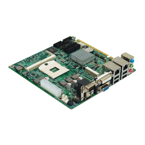
Norco MITX-6910 User manual

2
MITX-6910
Mini-ITXIndustrial Motherboard
USER ManualV1.0

Content
Chapter1.ProductIntroduction ................................................................................................1
1.1Overview...........................................................................................................................1
1.2Product Specification........................................................................................................1
Chapter2. Installation Instruction .............................................................................................4
2.1InterfaceLocationandDimension Diagram....................................................................4
2.2InstallationSteps...............................................................................................................4
2.3CPU&MemoryInstallation..............................................................................................5
2.4JumperSetting..................................................................................................................5
2.4.1CMOSContentClearance/HoldSetting JCC).................................................5
2.4.2Anti-virusBIOSWrite-protect JumperSetting JAV).........................................6
2.4.3COM2JumperSetting J5, J6, J7)....................................................................7
2.4.5LVDSVoltageSelectionJumperSetting JP3, J2)..............................................8
2.5InterfaceSpecification......................................................................................................9
2.5.1SATA&SATAPWRInterface SATA1, SATA2)...............................................10
2.5.2CF CardSocket Compact Flash)....................................................................10
2.5.3Serial Ports COM1,COM2, COM3-6, J5,J6)..................................................11
2.5.4DisplayInterface VGA, DVI, HDMI,LVDS)....................................................13
2.5.5LVDSPanelBacklight Control J3)..................................................................15
2.5.6USB_NetworkInterface USB_LAN1, USB_LAN2, USB1,USB2).................16
2.5.7GPIOPort GPIO1/2).......................................................................................17
2.5.8AudioInterface AUDIO, JAUDIO, JAMP).......................................................18
2.5.9Keyboard&MouseConnector KBMS)...........................................................19
2.5.10FANConnector...................................................................................................20
2.5.11MiniPCIEPort MINI_PCIE, J4)........................................................................21
2.5.12Expansion Interface...........................................................................................22
2.5.13Infrared Interface IRDA)................................................................................22
2.5.14PowerConnector(ATX).....................................................................................24
2.5.15Front Panel Connector JFP).........................................................................24
Chapter3.BIOSSetup...............................................................................................................27
BIOSUpgrading....................................................................................................................27
BIOSParameterConfiguration.............................................................................................27
BIOSFunction Setup............................................................................................................27
3.1MainMenu......................................................................................................................28
3.2Advanced Menu..............................................................................................................29
3.2.1ACPIConfiguration...............................................................................................29
3.2.2CPUConfiguration...............................................................................................30
3.2.3SATAConfiguration..............................................................................................31
3.2.4USB Configuration................................................................................................32
3.2.5SupperIOConfiguration......................................................................................33
3.2.6H/WMonitor..........................................................................................................33
3.2.7AMT Configuration................................................................................................34
3.2.8Serial Port ConsoleRedirection...........................................................................35
3.3ChipsetMenu..................................................................................................................36
3.3.1NorthBridge.........................................................................................................36
3.3.2SouthBridge.........................................................................................................37
3.4BootMenu.......................................................................................................................39
3.5SecurityMenu.................................................................................................................40
3.6Save&ExitMenu.............................................................................................................40
Appendix.......................................................................................................................................42
Appendix1. Watchdog ProgrammingGuide.......................................................................42
Appendix2. Glossary............................................................................................................44

Chapter1
ProductIntroduction

MITX-6910 Mini-ITXMotherboardBasedonIntelQM57
1
Chapter1.ProductIntroduction
1.1Overview
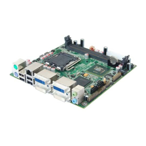
MITX-6910isatypeofMINI-ITXmotherboardbased on Intel QM57chipset, supportingIntel
processorCorei7/Corei5/CeleronP4500series.Boardprovides2*240pinSODIMMsockets
supportingDDRIII-800/1066MHzmemoryupto8G;2*SATA,1*50pin CFsocket;8*USB,
including2*doublelayerstandardUSBportsand2*2×5Headerinterfaces. IntermsofDisplay,
itadoptsIntelQM57integratedgraphiccontroller,providingVGA,DVI, HDMIandLVDSports
andVGA+LVDSdual independentdisplaysupported;IntermsofNetwork,boardadoptsIntel
82574L+Intel 82577chip,providing2*100/1000MbpsRJ45networkinterfaceandAMT6.0
supported.Besides,MITX-6910isalsofeatured byrichI/O,including6*COM,2*MINIPCIE
and1*PCI.
Boardalsoprovidesotheradvanced functions,suchas16BitGPIO,WatchdogTimer,
1*Infraredtransmission moduleand anti-viruswrite-protectBIOSfunction.
1.2ProductSpecification
StructureStandard
●LowpowerMini-ITXmotherboard
Dimension
●170mm X170mm L×W)
Processor
●Support Intel Corei7, Corei5, Celeron P4500CPU
Chipset
●Intel QM57
SystemMemory
●2*DDR3SO-DIMMsockets
●Support DDR3800/1066MHzmemoryupto8GB
Storage

MITX-6910 Mini-ITXMotherboardBasedonIntelQM57
2
●2*SATAadopt 7+15PINconnector
●CompactFlash:50PinSocket
●1*Mini-PCIESSD
Display
●Controller: Intel QM57 integrated graphiccontroller
●VGA:1*standardDB15
●DVI: 1*DVI-I (DVI-DorDVI-Aoptional )
●HDMI: 1*standardHDMI
●LVDS:dualchannel24bit LVDS
LAN
●AdoptIntel82574L+Intel 82577chip
●100/1000Mbps. 2*standardRJ45interface,AMT6.0supported
Audio
●1*triplelayerAudiointerfaceon therearpanel adoptsALC888,providingSpeak-out, Mic-in,
Line-INfunctions
●1*2x5PIN2.0mm
●1*1x4PINSpeak-OUT,6Waudioamplifier
USB
●8*USB2.0withESDprotection
●2*doublelayerUSB portson therearpanel,4*standardUSB ports
●2*2x5Header, abletobeconvertedto4*standardUSBports
I/O
●AdoptWinbondW83627HFI/Ochip
●1*2×4PINkeyboard&mouseinterface
●2*GPIO
●6*COMwithCOM1supportingRS232andCOM2supportingRS232/422/485
●1*5PINIRDA

MITX-6910 Mini-ITXMotherboardBasedonIntelQM57
3
Expansion Interface
●2*Mini-PCIE 1*Mini-PCIEsupportsSSD)
●1*PCIEX4,1*PCI
PowerSupply
●StandardATXpowersupply
Watchdog Timer
●Support HDDreset function
BIOS
●64MBSPIFlashBIOS
Environment
●OperatingTemperature: 0-60 32℉-140℉)
●StorageTemperature:-40 -80 -40℉-176℉)
●OperatingHumidity: 5%-90%relativehumidity,non-condensing.

Chapter2
Installation Instruction

MITX-6910 Mini-ITXMotherboardBasedonIntelQM57
4
Chapter2InstallationInstruction
2.1Interface Location and Dimension Diagram
FollowingpictureistheinterfaceindexforMITX-6910, whenyou installyourdevices,
pleaseconsult itandread thefollowing guide. Duringinstallationpleasecarefor
somedevices. Improperinstallationwilllead tosystemmalfunctions.
Note:During installation,inordertoprotect thepartsof theboard, pleaseputon
antistaticgloves.
MITX-6910InterfaceLocation andDimension Diagram
2.2Installation Steps
Pleaserefertothefollowingstepstoinstallyourcomputer:
1:AdjustallJumpersonMITX-6910accordingtothemanual.
2.InstallCPUandmemory
3.Installotherexpansion cards
4.Connectall thesignallines,cable, panel-controlcircuitryandpowersupply
5. FinishBIOSsetup

MITX-6910 Mini-ITXMotherboardBasedonIntelQM57
5
KeycomponentsofthismotherboardareIntegratedcircuit,andthese
componentswillbeeasilydamagedbyelectrostaticinfluence.So,before
installingthemotherboard,you shouldalwayskeepthefollowingprecautions
inmind:
1. Holdtheboardbytheedges; don'ttouchanycomponentsorpinsontheboard
2.Useaanti-staticwriststraporwearanti-staticgloveswhilegettingintouchwith
integratedcircuitcomponents(suchasCPU, RAM).
3.Placecomponentsinagroundedantistaticbag/pad whenthesecomponentsare
uninstalled.
4.Pleasemakesurethepowerswitchisdisconnectedbeforeinserting thepower
plug.
2.3CPU&MemoryInstallation
PleasefollowthestepsbelowtoinstallCPU:
1.PleasechooseaproperCPUthatmeetsthespecificationrequirementsandensurethe
installation isinplace.
2.MakesurethatthecoolingfinofCPUFANismatchingwellwiththeCPU
Boardprovidesonesystemmemorysocket. Wheninstallingmemorybank,pleasepay
attention tothefollowingtwopoints:
1.Whenfixing,makesurethenotchmatchsSO-DIMMsocketandthen insertmemorybank
intothesocket. Press it downtotight theconnection.
2. Choosethepropermemorybankthat supportsmotherboardspecification
2.4JumperSetting
Pleasesetupthejumpersaccordinglybeforeinstalling hardwaredevices.
Note: HowtoidentifyjumperandPIN1ofinterface
Pleaseobservethewordmarkofplugsocket,itwill use “1”orboldlineortriangularsymbols;
andpleaselookatthebackofPCB,eachweldspothasasquarpoint, thatisPIN1;Usually
thereisawithearrowbesidePIN1.
2.4.1CMOSContentClearance/HoldSetting JCC)
CMOSpowered byonboardbutton battery. CleanCMOSwill leadtoapermanent
eliminationoftheprevioussystemsettingandbacktotheoriginal(default setting)system

MITX-6910 Mini-ITXMotherboardBasedonIntelQM57
6
settings.
Steps: 1)Turnoffthecomputer,disconnect thepowersupply
2)Usejumpercap shortJCC Pin1andPin2for5~6sec,Thenrestorethedefault
setting ofPin2 andPin3.;
3)Turnon thecomputer,thenpress DELkeyintotheBIOSsettingandreloadthe
optimized defaults.
4)Saveandexit setting.
Setting JCC
1-2 ClearCMOS(BIOSrenew toinitialization)
2-3 Nomalstatus(default)
DonotclearCMOSwhenpoweron,otherwiseitwilldamage themotherboard.
2.4.2Anti-virusBIOSWrite-protectJumperSetting JAV)
The BIOSoftheboardiscontained intheFlashROM. If thejumperJAVissetasclosed,you
willbeunabletoflashtheBIOSandthesystemBIOSisalsoprotectedfrombeing attackedby
seriousvirussuchasCIHvirus. If youwanttoflashtheBIOS, pleasestethisjumperopen.

MITX-6910 Mini-ITXMotherboardBasedonIntelQM57
7
Setting JAV
Close DisabletoflashBIOS(default)
Open EnabletoflashBIOS
2.4.3COM2JumperSetting J5,J6,J7)
COM2canbeconfigured tooperatein RS-232, RS-422, orRS-485mode(RS232fordefault.).
ThisisdoneviaJ5,J6andJ7.

MITX-6910 Mini-ITXMotherboardBasedonIntelQM57
8
2.4.5LVDSVoltageSelectionJumperSetting JP3,J2)
BeforeusingLCDdevice,pleasemakesurethepowersupplyisadjustedaccordingly.To
adjust thepowersupply&voltage,pleaseconfig thejumperofJ2andJP3.
COM2RS232 Default)COM2RS422 COM2RS485
J5 3-54-6 J5 1-32-4 J5 1-32-4
J6 3-54-6 J6 1-32-4 J6 1-32-4
J7 1-2 J7 3-4 J7 5-67-8
J6/J5
J7

MITX-6910 Mini-ITXMotherboardBasedonIntelQM57
9
Setting JP3
1-2 +5V
2-3 +3.3V
2.5Interface Specification
Pleasereadthismanualfirst beforeconnectingexternalconnectorsincaseofanydamage
tothemotherboard.

MITX-6910 Mini-ITXMotherboardBasedonIntelQM57
10
2.5.1SATA&SATAHDDPWRInterface SATA1, SATA2)
SATA1, SATA2:
Pin SignalName Pin SignalName
1 GND P4 GND
2 TX+ P5 GND
3 TX- P6 GND
4 GND P7 VCC
5 RX- P8 VCC
6 RX+ P9 VCC
7 GND P10 GND
8 NC P11 GND
9 GND P12 GND
10 NC P13 +12V
P1 VCC3 P14 +12V
P2 VCC3 P15 +12V
P3 VCC3
2.5.2CFCardSocket CompactFlash)
Rearpanel providesone50Pin standardCFcardsocket

MITX-6910 Mini-ITXMotherboardBasedonIntelQM57
11
2.5.3SerialPort COM1, COM2, COM3-6,J5,J6)
Boardprovides6*Serial Ports. COM1adoptsDB9interface. COM2-6needtoconverttoDB9
interfacetoconnectexternal devices.Userscan choosetoopen orcloseortheIRQ&I/O
address viaBIOSconfiguration.
COM1&COM2support RS232.COM2alsosupportsRS422/485. Usercan select
transmissionmodeforCOM2viaJumperSetting.DetailsrefertoChapter2.4.3 “COM2Jumper
Setting”
COM1:
Pin SignalName
1 DCD
2 RXD
3 TXD
4 DTR
5 GND
6 DSR
7 RTS
8 CTS
COM2

MITX-6910 Mini-ITXMotherboardBasedonIntelQM57
12
9 RI
COM2:
SignalName Pin SignalName
DCD 1 2 DSR
RX 3 4 RTS
TX 5 6 CTS
DTR 7 8 RI
GND 9 10 GND
COM3-6:
SignalName Pin SignalName
HDCD#3 1 2 HDSR#3
HSIN3 3 4 HRTS#3
HSOUT3 5 6 HCTS#3
HDTR#3 7 8 HRT#3
GND 9 10 GND
HDCD#4 11 12 HDSR#4
HSIN4 13 14 HRTS#4
HSOUT4 15 16 HCTS#4
HDTR#4 17 18 HRT#4
GND 19 20 GND
HDCD#5 21 22 HDSR#5
HSIN5 23 24 HRTS#5
HSOUT5 25 26 HCTS#5
HDTR#5 27 28 HRT#5
GND 29 30 GND
HDCD#6 31 32 HDSR#6
HSIN6 33 34 HRTS#6
HSOUT6 35 36 HCTS#6
HDTR#6 37 38 HRT#6
GND 39 40 GND

MITX-6910 Mini-ITXMotherboardBasedonIntelQM57
13
2.5.4DisplayInterface VGA, DVI, HDMI, LVDS)
VGA:
Pin SignalName Pin SignalName Pin SignalName
1 RED 6 GND 11 NC
2 GREEN 7 GND 12 SDA_R
3 BLUE 8 GND 13 HS_R
4 NC 9 VCC 14 VS_R
5 GND 10 GND 15 SCL_R
DVI:
SignalName Pin SignalName
TDC2# 1 2 TDC2
GND 3 4 NC
NC 5 6 SC-DDC
SD-DDC 7 8 NC
TDC1# 9 10 TDC1
GND 11 12 NC
NC 13 14 VCC
GND 15 16 HP-DETECT

MITX-6910 Mini-ITXMotherboardBasedonIntelQM57
14
TDC0# 17 18 TDC0
GND 19 20 NC
NC 21 22 GND
TLC 23 24 TLC#
GND 25 26 GND
NC 27 28 NC
HDMI:
SignalName Pin SignalName
D2+ 1 2 D2Shield
D2- 3 4 D1+
D1Shield 5 6 D1-
D0+ 7 8 D0Shield
D0- 9 10 CK+
CKShield 11 12 CK-
CERemote 13 14 NC
DDC CLK 15 16 DDC DATA
GND 17 18 +5V
HPDET 19 20 SHELL0
SHELL1 21 22 SHELL2
SHELL3 23 24 SHELL4
SHELL5 25 26 SHELL6
SHELL7 27 28 SHELL8
SHELL9 29 30 SHELL10
SHELL11 31
LVDS:
SignalName Pin SignalName
VDD_PANEL 1 2 VDD_PANEL
GND 3 4 GND
LVDSA_DATA0# 5 6 LVDSB_DATA0#
LVDSA_DATA0 7 8 LVDSB_DATA0
GND 9 10 GND
LVDSA_DATA1# 11 12 LVDSB_DATA1#
LVDSA_DATA1 13 14 LVDSB_DATA1

MITX-6910 Mini-ITXMotherboardBasedonIntelQM57
15
GND 15 16 GND
LVDSA_DATA2# 17 18 LVDSB_DATA2#
LVDSA_DATA2 19 20 LVDSB_DATA2
GND 21 22 GND
LVDSA_CLK# 23 24 LVDSB_CLK#
LVDSA_CLK 25 26 LVDSB_CLK
GND 27 28 GND
LVDS_DDV_DATA 29 30 LVDS_DDC_CLK
GND 31 32 GND
LVDSA_DATA3# 33 34 LVDSB_DATA3#
LVDSA_DATA3 35 36 LVDSB_DATA3
VCC3 37 38 GND
NC 39 40 NC
2.5.5LVDSPanelBacklightControl J3)
J3isused toadjustLVDSbacklightbrightness.
J3:
Pin SignalName
1 +12V
15
Table of contents
Other Norco Motherboard manuals

Norco
Norco MITX-6854 User manual

Norco
Norco POS-7893 User manual

Norco
Norco MITX-6922 User manual

Norco
Norco MITX-6892 User manual

Norco
Norco EMB-4850 User manual

Norco
Norco MITX-6891 User manual

Norco
Norco EMB-3503 User manual

Norco
Norco BPC-7936 User manual

Norco
Norco EMB-3682 User manual

Norco
Norco MITX-6973 User manual

Norco
Norco MITX-6934 User manual

Norco
Norco MITX-6930 User manual

Norco
Norco MITX-6946 User manual

Norco
Norco FWMB-7550 User manual

Norco
Norco EMB-7540 User manual

Norco
Norco SOM-6503 User manual

Norco
Norco BPC-7934 User manual

Norco
Norco MITX-6854 User manual

Norco
Norco SOMB-073 User manual

Norco
Norco SOM-6670 User manual