BCS BF 80/175 User manual

MANUALE D’USO E MANUTENZIONE Codice 90103089 Edizione
OWNER’S MANUAL Code 90103089 Edition
MANUEL D’ENTRETIEN Code 90103089 Edition 03.10
MANUAL DE USO Y MANTENIMIENTO Codigo 90103089 Edición
WARTUNGSANLEITUNG Kodezahl 90103089 Ausgabe
BCS S.p.A.
BCS S.p.A.BCS S.p.A.
BCS S.p.A. –
––
– V.le Mazzini, 161
V.le Mazzini, 161V.le Mazzini, 161
V.le Mazzini, 161 –
––
– 20081 ABBIATEGRASSO
20081 ABBIATEGRASSO20081 ABBIATEGRASSO
20081 ABBIATEGRASSO –
––
– MI
MIMI
MI –
––
– Italia
ItaliaItalia
Italia
FERRARI
FERRARIFERRARI
FERRARI –
––
–
Div. della BCS S.p.A.
PASQUALI
PASQUALIPASQUALI
PASQUALI –
––
–
Div. della BCS S.p.A.
BARRA FALCIANTE
CUTTER BAR
BARRE DE COUPE
BARRA DE CORTE
MÄHBALKEN
•MODELLO
•MODEL
•MODELE
•MODELO
•MODELL
BF 80 / 175
BF 80 / 175BF 80 / 175
BF 80 / 175
BF 80 laterale
BF 80 lateraleBF 80 laterale
BF 80 laterale
BF 80 lateral
BF 80 lateralBF 80 lateral
BF 80 lateral
BF 80 latérale
BF 80 latéraleBF 80 latérale
BF 80 latérale
BF 80 lateral
BF 80 lateralBF 80 lateral
BF 80 lateral
seitlicher BF 80
seitlicher BF 80seitlicher BF 80
seitlicher BF 80

2
INDICE
I
INTRODUZIONE
MONTAGGIO
NORME DI SICUREZZA
PROVA DI FUNZIONAMENTO
MANUTENZIONE
REGOLAZIONE PREMILAMA
REGOLAZIONE LAMA
SOSTITUZIONE LAMA
SOSTITUZIONE PERNO DI TRASCINAMENTO
MONTAGGIO PIASTRINE DUPLEX
pag. 3
" 4
" 11
" 13
" 14
" 16
" 18
" 18
" 20
" 21
GARANZIA
MODALITA' DI VENDITA DEI RICAMBI
pag. 22
" 23
INDE
X
GB
INTRODUCTION
ASSEMBLY
SAFETY PRECAUTIONS
OPERATION TEST
MAINTENANCE
BLADE HOLDER ADJUSTMENT
BLADE ADJUSTMENT
BLADE REPLACEMENT
REPLACEMENT OF TRACTION PIN
DOUBLE MOUNTING PLATES
page 3
" 4
" 11
" 13
" 14
" 16
" 18
" 18
" 20
" 21
GUARANTEE
ORDERING SPARE PARTS
page 22
" 23
CONTENU
F
INTRODUCTION
MONTAGE
REGLES DE SÉCURITÉ
ESSAIS DE FONCTIONNEMENT
ENTRETIEN
REGLAGE DES PRESSE-LAMES
REGULATION DE LA LAME
REPLACEMENT DE LA LAME
SUBSTIT. DU GOUJON DE TRAINEMENT
MONTAGE PLATINES DUPLEX
page 3
" 4
" 11
" 13
" 14
" 16
" 18
" 18
" 20
" 21
GARANTIE
MODALITÉ DE VENTE DES PIECES DE
RECHANGE
page 22
" 23
INDICE
E
INTRODUCCIÓN
MONTAJE
NORMAS DE SEGURIDAD
PRUEBAS DE FUNCIONAMIENTO
MANTENIMIENTO
REGULACIÓN DE LA GUIA-CUCHILLAS
REGULACIÓN DE LA CUCHILLA
SUSTITUCIÓN DE CUCHILLA
CAMBIO DEL PERNO DE ARRASTRE
MONTAJE PLACAS DUPLEX
pag. 3
" 4
" 11
" 13
" 14
" 16
" 18
" 18
" 20
" 21
GARANTIA
SOLICITUD DE RICAMBIOS
pag. 22
" 23
INHALT
D
ENLEITUNG
MONTAGE
SICHERHEITSHINWEIS
BETRIEBSPRÜFUNG
WARTUNG
EINSTELLUNG DES MESSERHALTERS
MESSERREINSTELLUNG
MESSERERSATZ
AUSWECHSELN DES ZUGZAPFENS
MONTAGE DER DUPLEX-PLÄTTCHEN
Seite 3
" 4
" 11
" 13
" 14
" 16
" 18
" 18
" 20
" 21
GARANTIE
VERKAUF DER ERSATZTEILE
Seite 22
" 23

3
INTRODUZIONE
I
Le macchine comprese in questo manuale sono
costruite in accordo con la Direttiva Macchine
Europea e sue modificazioni.
Il Costruttore si complimenta con Voi per la scelta di un
nostro prodotto garantendoVi il massimo dell'assistenza e
della collaborazione che da sempre contraddistinguono il
nostro marchio.
Questa pubblicazione Vi aiuterà a conoscere meglio la
Vostra macchina. Se verrà usata seguendo queste istru-
zioni Vi durerà molti anni e Vi sarà di prezioso aiuto per
svolgere i Vostri lavori agricoli.
Vi raccomandiamo pertanto di leggere attentamente que-
ste pagine e di seguire sempre i consigli.
INTRODUCTION
GB
The machines described in this manual are
built in accordance with the European
Machines Directive and its modifications.
The Manufacturer congratulates with You on Your purcha-
sing a machine from our range. We will grant the assistan-
ce and cooperation which have always been a feature of
our products.
If used in accordance with the instructions contained in
your owners manual, your machine will last many years
and will prove to be of an invaluable assistance to you.
We therefore recommend that You read the manual care-
fully and follow the advice given.
INTRODUCTION
F
Les machines décrites dans ce manuel sont
construites en accord avec la Directive
Européenne des Machines et ses modifications.
Le Constructeur Vous félicite pour le choix d’un de nos
produits en Vous assurant le maximum de notre assistan-
ce et collaboration qui on toujours distingué notre marque.
Cette publication Vous aidera à mieux connaître Votre ma-
chine. Si Vous l'utilisez conformément aux instructions
contenues dans ces manuel, il durera de nombreuses an-
nées et sera pour Vous une aide précieuse pour Vos tra-
vaux agricoles.
Nous Vous recommendons, par conséquent, de lire ces
pages avec attention et de suivre scrupuleusement les
conseils.
INTRODUCCION
E
Las máquinas incluidas en este manual
están construidas según la Directriz Europea
de las Máquinas y sus enmiendas.
El Constructor se alegra con Usted por haber escogido
nuestro producto y puede asegurar la maxima asistencia y
collaboración que siempre han caracterizado nuestra mar-
ca.
Este libro le ayudará a conocer mejor su máquina. Si la
usa siguiendo estas instrucciones le durerà muchos años y
la será de gran ayuda para desarrollar sus trabajo agríco-
las.
Le recomendamos pues, leer atentamente estas páginas y
seguir siempre los consejos que en ellas encontrarà.
ENLEITUNG
D
Die in dem vorliegenden Handbuch
beschriebenen Maschinen sind der
Europäische Richtlinie über Maschinen und
ihren Abänderungen gemäß gebaut worden.
Die Hersteller erfreut sich um Ihre Wahl. Unsere Firma wird
zweifellos Ihnen seine beste Wartung und Zusammenar-
beit bieten, die seit immer Produkte kenn zeichen.
Wenn Sie in diesem Handbuch erteilten Anleitungen be-
herzigen, wird Ihre Maschine über lange Zeit eine wertvol-
le Hilfe sein.
Bitte lesen Sie daher die vorliegende Bedienungsanleitung
aufmerksam durch und befolgen Sie die erteilten Ratschlä-
ge.

4
MONTAGGIO
I
Una volta aperta la scatola, procedere al montaggio come
segue.
ATTENZIONE !
Prima di togliere i bulloni, osservare bene come sono
montati perché in fase di preparazione sono stati pre-
disposti come serviranno nel montaggio.
Montare la protezione superiore A(fig.1) sul gruppo co-
mando Be SERRARE.
Utilizzare una delle varie possibilità di fissaggio della prote-
zione (fig.2-3) in funzione del tipo di gruppo di comando e
del modello di macchina.
ATTENZIONE !
LE LAME TAGLIANO. USARE GUANTI ROBUSTI (fig.4).
ASSEMBLY
GB
Open the box and assemble the cutter bar in the following
manner.
WARNING !
Before removing any bolts, make note of their location
so that they may be reinstalled in the hole from which
they are removed.
Secure the control unit hood A(fig.1) to the control group
B. TIGHTEN the bolts securely!
Use one of the various safety guard fastening possibilities
(fig.2-3) in relation to the type of drive unit and machine
model.
WARNING !
THE BLADES ARE VERY SHARP, SO WEAR GLOVES
(fig.4) TO PROTECT YOUR HANDS FROM CUTS !
MONTAGE
F
Après avoir ouvert le boîte, effectuer le montage comme
suit:
ATTENTION !
Avant de démonter les boulons, bien observer comme ils
sont montés, car pendant leur préparation ils sont
disposés dans la manière qui servira pour leur montage.
Monter la protection supérieur A(fig.1) sur le groupe de
commande B.
SERRER !
Utiliser une des diverses possibilités de fixage de la pro-
tection (fig.2-3) selon le type de groupe de commande et
du modèle de la machine.
ATTENTION !
LES LAMES COUPENT. METTEZ DES GANTS RO-
BUSTES (fig.4).
MONTAJE
E
Una vez aberta la caja proceder al montaje come sigue:
ATENCIÓN !
Antes de desmontar los bulones observar bien como
van montados porque víenen predispuestos para su
uso en el montaje.
Montar la protección superior A(fig.1) en el grupo mando B.
ATORNILLAR !
Utilizar una de las varias posibilidades de sujeción de la
protección (fig. 2-3) en función del tipo de grupo de mando
y del modelo de máquina.
ATENCIÓN !
LAS CUCHILLAS CORTAN ES PREFERIBLE USAR
GUANTES ROBUSTOS (fig.4).
MONTAGE
D
Den Karton öffnen und die Montage wie folgt vornehmen:
ACHTUNG !
Vor der Demontage der Bolzen gut bemerken, wie sie
montiert sind. Sie werden tatsächlich in der für die
Montage nötigen Weise vorbereitet.
Vorderen Schutz A(Bild 1) auf Antriebsgruppe B montieren.
VERSCHRAUBEN !
Die verschiedenen Befestigungsmöglichkeiten der Ab-
deckung (Bilder 2-3) nach der Art des Steueraggregats
und dem Maschinenmodell verwenden.
ACHTUNG !
MESSER SCHNEIDEN.
STARKE HANDSCHUHE ZIEHEN (Bild 4).

5

6
MONTAGGIO
I
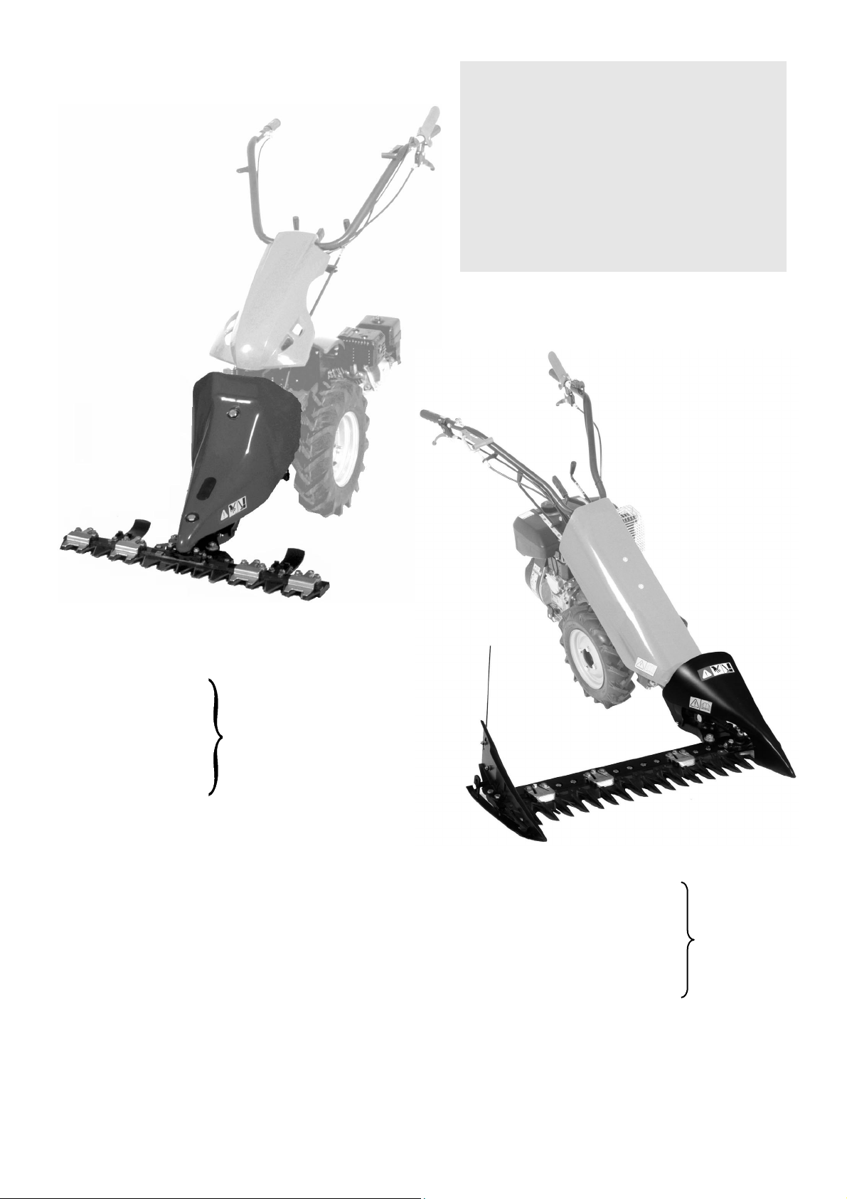
Fare attenzione che il perno entri nella sua sede quindi
montare la barra falciante Bal gruppo comando Acon i
due dadi e le rondelle (fig.5) e serrare forte.
N.B. Per il montaggio del gruppo falciante “Duplex Bilama”
(a doppia manovella) prestare attenzione che entrambi i
perni Fe G entrino nella loro sede (fig.5b), quindi proce-
dere come detto sopra.
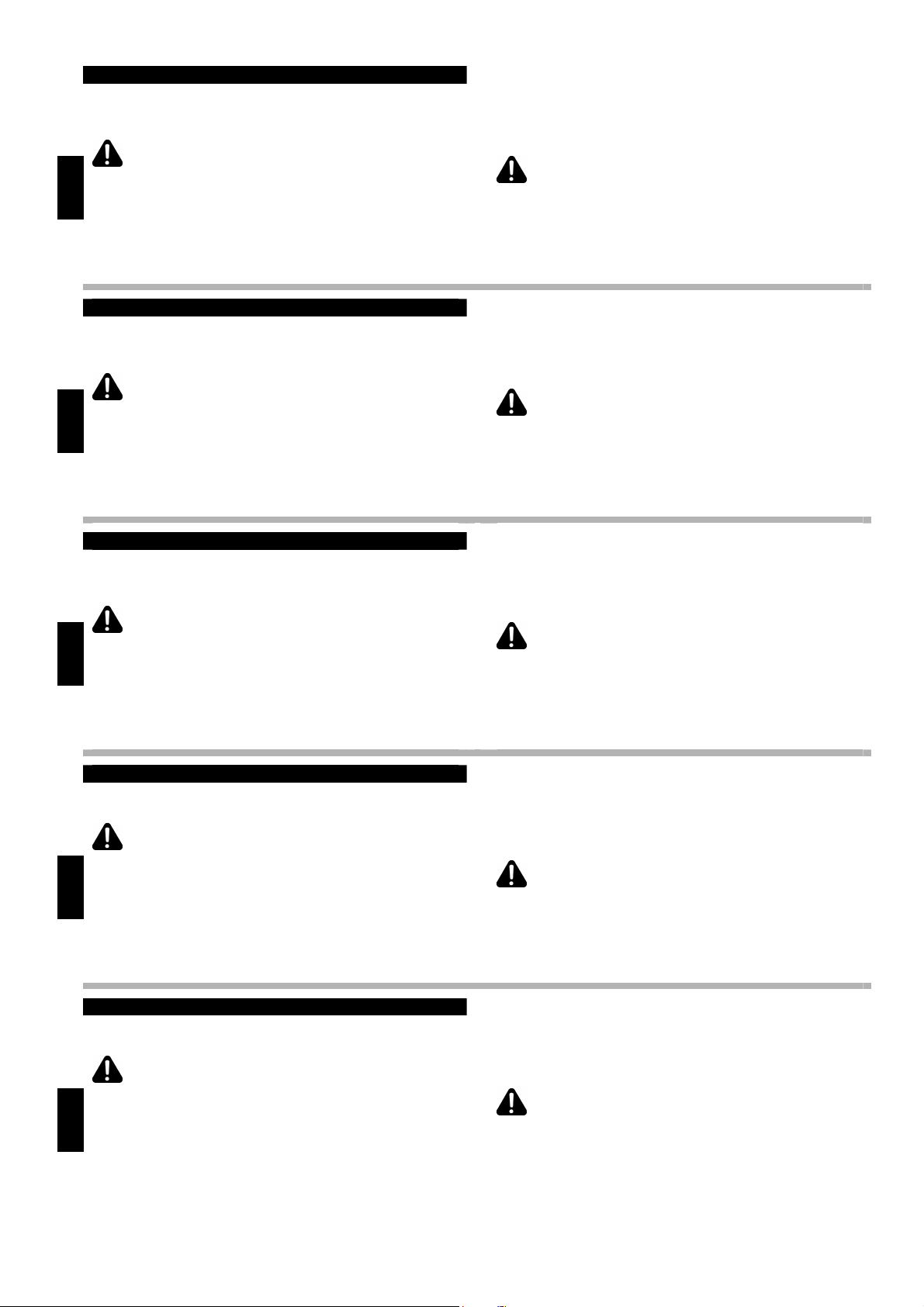
SE E’ NECESSARIO FARE UN TAGLIO DELL’ERBA AL-
TO, PROCEDERE COME SEGUE: montare le slitte di re-
golazione altezza di taglio Csulla barra falciante con le viti
in dotazione (fig.6) se si deve tagliare normalmente è pre-
feribile non montarle. Per tagliare vicino a muri o piante è
bene montare le protezioni laterali D. FARE ATTENZIONE
che la protezione sia accostata al dente (fig.7).
La barra “Duplex Bilama” non ha né protezioni laterali, né
slitte di regolazione.
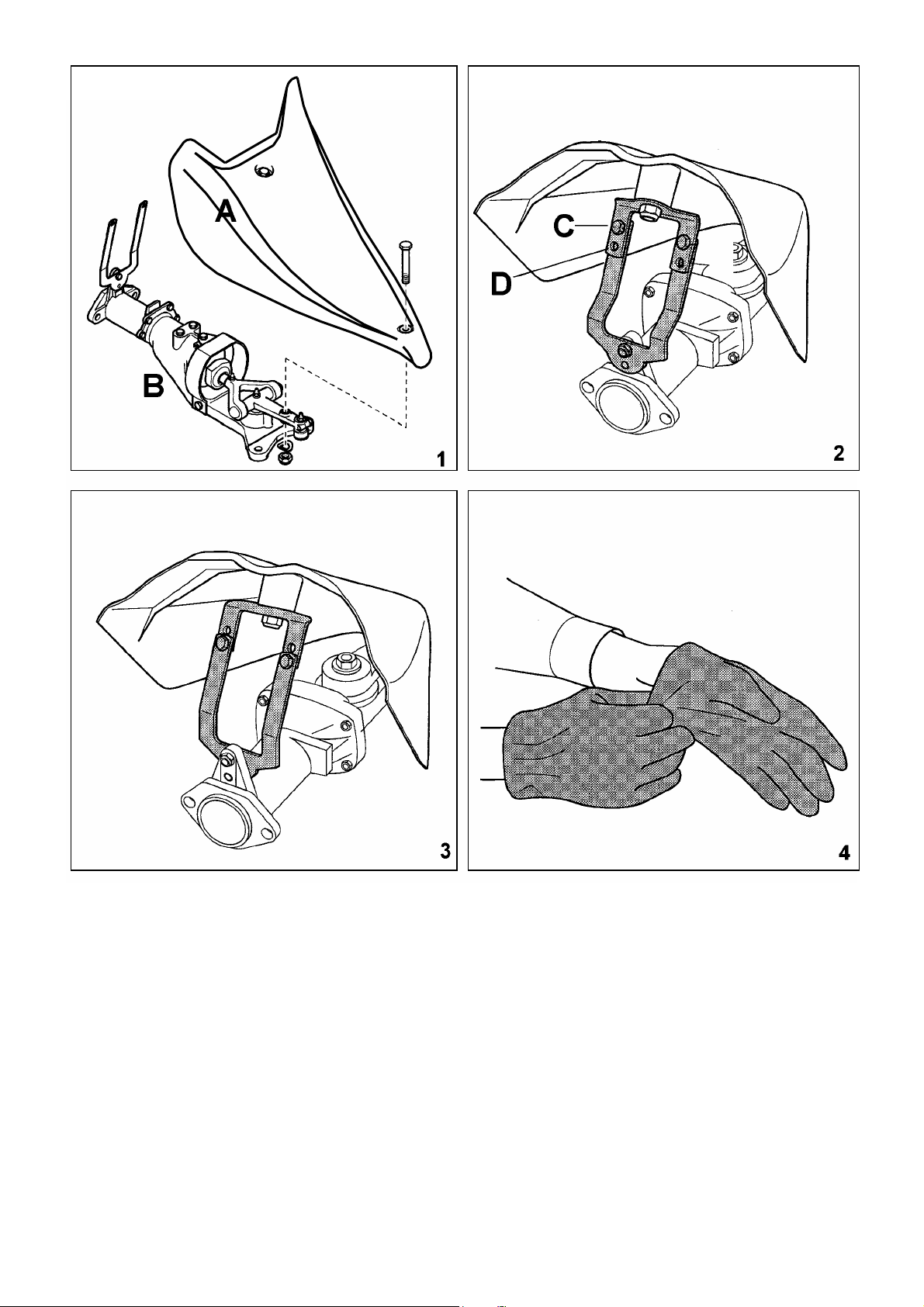
Per montare la protezione laterale sulla barra Europa
da 0,80:
•
svitare e togliere il premilama E(fig.8);
•
posizionare la protezione laterale e fissarla con le viti in
dotazione (fig.9).
ASSEMBLY
GB
Verify that the stud seats properly in its housing, then
mount the cutting bar Bto control panel Aby the two nuts
and washers (fig.5) and tighten hardly.
N.B. For the assembly of the “Duplex Double Blade” mo-
wing group (with a double crank mechanism), make certain
both pins Fand Gfit into their housings (fig.5b), then
proceed as described above.
IF NECESSARY CUT HIGH: install the cutting height ad-
justment slides Con the cutter bar using the bolts provided
(fig.6), if a normal cut has to be performed it is advisable
not to mount them. Tu cut near walls or trees, fit the
optional side protection D. MAKE SURE that the protector
fits flush against the outer tooth (fig.7).
The “Duplex Double Blade” bar has neither lateral pro-
tections nor adjustment carriages.
To fit the side protection on the 30” Europa cutter bar:
•
remove the blade holder E(fig.8);
•
position the side protection and fasten it with the bolts
supplied (fig.9).
MONT
A
GE
F
Vérifier que le pivot entre dans son siège, monter la barre
de coupe Bau groupe de commande Aavec les deux
ecrous et les rondelles (fig.5) et serrer fortement.
N.B. Pour le montage du groupe faucheur “Duplex Bilame”
(à double manivelle), il faut faire très attention que les deux
pivots Fet Gentrent dans leur emplacement (fig.5b), par
conséquent il faut procéder selon la description ci-dessus.
SI NECESSAIRE COUPER HAUT: monter les traineaux
réglage de la hauter de coupe Csur la barre de coupe
avec les vis (fig.6); si on doit couper normalement, il est
préférable de ne pas les monter. Pour couper près de
murs ou plantes il est bien de monter les protections
latérales D. ATTENTION: la protection doit être approchée
au dent (fig. 7). La barre “Duplex Bilame” n’a ni protections
latérales, ni glissières de réglage.
Pour monter la protection latérale sur la barre Europa
de 0,80 mt:
•
dévisser et ôter le presse-lame E(fig.8);
•
positionner la protection latérale et fixer-la avec les vis
délivrées (fig.9).
MONTAJE
E
Observar que el perno entre en su alojamiento, luego
montar la barra de corte Bal grupo mando Acon las dos
tuercas y las arandelas (fig.5) y atornillar fuertemente.
Nota: para el montaje del grupo de siega “Duplex Bilama”
(de doble manivela) hay que tener la precaución de que
los dos pernos Fy Gentren en su sitio (fig.5b) y hacer lo
que se menciona más arriba.
SI SE NECESITA CORTAR ALTO: montar los patines de
regulación de altura de corte Csobre la barra de corte, con
los tornillos de la dotación (fig.6), si se debe cortar normal-
mente es preferible no montarlos. Para el corte cerca los
muros o plantas es aconsejable montar las protecciónes
laterales D. PONER ATENCIÓN que la protección esté
arrimada al diente (fig.7).
La barra “Duplex Bilama” no tiene ni protecciones laterales
ni guías de regulación.
Para montar la protección lateral en la barra de 0,80
Europa:
•
destornillar y sacar la guia cuchilla E(fig.8);
•
colocar la protección lateral y fijarla con los tornillos de
dotacion (fig.9).
MONTAGE
D
Prüfen, daß des Lager in seinen Sitz eindrigt, Mähbalken B
an Antriebsgruppe Adurch die zwei Muttern und Unter-
legsscheiben montieren (Bild 5) und kräftig verschrauben.
Hinweis: Beim Anbringen des Mähaggregats “Duplex
Bilama” (mit Doppelkurbel) darauf achten, dass beide
Zapfen Fund Gin ihre Aufnahme gesetzt werden (Bild 5b);
daraufhin wie beschrieben vorgehen.
BEIM HOCH SCHNEIDEN: Schlitten Cfür den Schnitt-
höheneinstellung auf Mähbalken durch die gelieferten
Schrauben (Bild 6) montieren. Wenn man normales
Schneiden durchführen muß, ist es besser, die Schrauben
nicht zu montieren. Um neben Mauern und Pflanzen zu
schneiden, Seitenschütze Dmontieren. Der Schutz muß
dem Finger genähert werden (Bild 7).
Der “Duplex Bilama” Balken hat weder Seitenabsicherun-
gen noch Stellführungen.
Um den Seitenschutz auf den Mähbalken Europa 0,80
mt. zu montieren:
•
den Messerhalter abschrauben und entfernen (Bild 8);
•
den Seitenschutz mit den gelieferten Schrauben fest-
machen (Bild 9).

7
5b
F
G

8
MONTAGGIO
I
•
Rimuovere il bullone posizionato sul premilama nella
parte inferiore (fig.10).
•
Avvitare la vite in dotazione (M8x20) dalla parte supe-
riore del premilama (fig.11).
•
Avvitare il relativo dado (fig.12) e rimontare il premilama
(fig.13).
•
Regolare il premilama (vedere relativo capitolo) (fig.14).
A questo punto è possibile fissare la barra falciante com-
pleta sulla flangia della macchina.
ASSEMBLY
GB
•
Remove the bolt in the lower side of the blade holder
(fig.10).
•
Screw the M8x20 provided bolt in the upper part of the
blade holder all the way down (fig.11).
•
Install the jam nut that locks the bolt in place (fig.12) and
mount the blade-holder again (fig.13).
•
Adjust the blade holder (see related chapter) (fig.14).
At this point it is possible to fix the complete cutting bar on
the flange of the machine.
MONTAGE
F
•
Ôter le bouton positionné sur le coté inférieur du presse-
lame (fig.10).
•
Visser la vis délivrée (M8x20) du coté supérieur du
presse-lame (fig.11).
•
Visser l'ecrou correspondant (fig.12) remonter le presse-
lame (fig.13).
•
Régler le presse-lame (voir le chapitre correspondant)
(fig.14).
A ce point il est possible de fixer la barre de coupe com-
plète à la bride de la machine.
MONTAJE
E
•
Sacar el bulon colocado sobre la guia cuchilla en la
parte inferior (fig.10).
•
Atornillar el tornillo de dotación (M8x20) de la parte
superior de la guia cuchilla (fig.11).
•
Entonces atornillar la correspondiente turca (fig.12) y
volver a montar la guia cuchilla (fig.13).
•
Reglar la guia cuchilla (ver el capitulo relativo) (fig.14).
En este punto es posible fijar la barra de corte completa a
la brida de la máquina.
MONTAGE
D
•
Den sich in der unteren Seite des Messerhalters befind-
liche Bolzen beseitigen (Bild 10).
•
Die gelieferte Schraube M8x20 in der oberen Seite des
Messerhalters anschrauben (Bild 11).
•
Die entsprechende Mutter anschrauben (Bild 12) und
den Messerhalter wieder montieren (Bild 13).
•
Den Messerhalter einstellen (siehe entsprechendes Ka-
pitel) (Bild 14).
Jetzt können Sie den kompletten Mähbalken dem Maschi-
nenflansch befestigen.

9
MONTAGGIO
I
Nelle versioni delle barre falcianti con i denti a punta,
montare sempre le scarpe laterali e i convogliatori.
•
Togliere le slitte inferiori A delle scarpe B (fig.15).
•
Posizionare la prima punta della barra falciante sull'allog-
giamento della scarpa e fissare con viti, rondelle e dadi
(fig.16).
•
Rimontare le slitte e regolarle all'altezza di lavoro deside-
rata quindi montare i convogliatori C (fig.17).
Anche in questo caso, per tagliare vicino a muri o piante è
bene montare le protezioni laterali D(fig.18).
Per il montaggio della barra laterale EUROPA vedi fig.18/
1, per quello della barra laterale SEMIFITTA vedi fig.18/2.
Per l'applicazione delle barre alle macchine, fare riferimen-
to agli specifici manuali d'uso delle macchine.
N.B. La barra Duplex, sebbene abbia i denti a punta, non
ha scarpe laterali né convogliatori.
ASSEMBLY
GB
When using the cutter bar with the pointed teeth, side
shoes and conveyors must always be fitted.
•
Remove the lower slides A of the shoes B (fig.15).
•
Position the first point of the cutter bar on the shoe
housing using nuts, bolts and washers (fig.16).
•
Reinstall the slides and adjust them at the wished height
then fit the conveyors C (fig.17).
Even in this case to cut near walls or trees, fit the optional
side protections D(fig.18).
To mount the side bar “EUROPA” see fig.18/1, to mount
the HALF THICKNESS side bar see fig.18/2.
For the application of the bars to the machine, refer to the
specific user manual for the machines.
N.B. Although the Duplex bar has pointed teeth, it has
neither side shoes nor conveyors.
MONTAGE
F
Pour les barres de coupe avec les dents à pointe on
doit toujours monter les patins latéraux et les con-
voyeurs.
•
Ôter les traineaux inférieurs A des patins B (fig.15).
•
Mettre la première pointe de la barre de coupe sur le
siège des patins avec les vis, rondelles et écrous (fig.16).
•
Monter les traineaux et les régler à la hauteur de travail
désirée, monter les convoyeurs C(fig.17).
Aussi dans ce cas, pour couper près de murs ou plantes, il
est bien de monter les protections latérales D(fig.18).
Pour le montage de la barre latérale EUROPA voir fig.18/1,
pour ceux de la barre latérale SEMI–SERRÉE voir fig.18/2.
Pour l’application des barres sur les machines, faire réfé-
rence aux manuels d’utilisation spécifiques des machines.
N.B. La barre Duplex, bien qu’elle ait des dents à pointe,
n’a pas de patins latéraux ni de convoyeurs.
MONTAJE
E
En las versiones de la barra de corte con los dientes
con punta, se necesita montar siempre las galgas
laterales y los deflectores.
•
Sacar los patines inferiores A de la galgas B (fig.15).
•
Posicionar la primera punta de la barra de corte en el
alojamiento de la galga con tornillos arandelas y tuercas
(fig.16).
•
Volver a montar los patines y regularlos a la altura de
trabajo deseada, entonces montar los deflectores C
(fig.17).
En este caso también para cortar cerca de muros o plan-
tas es preferible montar las protecciónes laterales D(fig.
18).
Para el montaje de la barra de corte lateral EUROPA ver
fig.18/1, por el montaje de la barra lateral SEMI-RECIA ver
fig.18/2.
Para la aplicación de las barras a las máquinas, consultar
los manuales específicos de uso de las máquinas.
Nota. La barra Duplex, aunque tenga los dientes con
punta, no tiene ni galgas laterales ni deflectores.
MONTAGE
D
Bei den Mähbalken mit Spitzzähnen muß man Seiten-
schuhe und Förderer immer montieren.
•
Die unteren Schuhschlitten A – B beseitigen (Bild 15).
•
Der erste Spitz des Mähbalkens auf Schuhgehäuse mit
Schrauben, Scheiben und Muttern stellen (Bild 16).
•
Schlitten wieder montieren und zur gewünschten Ar-
beitshöhe einstellen.
•
Förderer C montieren (Bild 17).
Um neben den Mauern und Pflanzen zu schneiden, Sei-
tenschütze Dmontieren (Bild 18).
Um der seitigen Mähbalken EUROPA zu montieren siehe
Bild 18/1, für die Montage des HALB GEDICHTEN Mäh-
balkens sieh Bild 18/2.
Zum Anbringen der Balken siehe entsprechende Betriebs-
anleitungen der Maschinen.
Hinweis: Obwohl der Duplex-Balken über Spitzzähne ver-
fügt, hat er jedoch weder Seitenschuhe noch Förder.

10

11
NORME DI SICUREZZ
A
I
•
Per qualsiasi spostamento montare sempre la protezio-
ne anteriore A(fig.19).
•
Durante il lavoro USARE GUANTI ROBUSTI.
•
LEGGERE tutte le etichette poste sulla macchina e
sull’attrezzo (fig.20).
•
Indossare indumenti adatti al lavoro, MAI a piedi nudi o
sandali (fig.21).
•
NON USARE la macchina in vicinanza di bambini o ani-
mali (fig.22).
•
L’utilizzatore della macchina è RESPONSABILE dei
danni a persone o beni altrui.
•
NON CORRERE, ma camminare.
•
ATTENZIONE: non lavorare su terreni con pendenze
superiori al 20%; sui pendii non lavorare né in salita, né in
discesa, ma trasversalmente, facendo particolare attenzio-
ne ai cambi di direzione.
Se ci fosse pericolo di scivolare su pendenze, la macchina
dovrà essere tenuta da un accompagnatore con un ba-
stone o con una fune.
L’accompagnatore deve trovarsi al di sopra della macchina
e ad una distanza sufficiente dall’attrezzo.
SAFETY PRECAUTIONS
GB
•
During transport or any time the cutter bar is not use,
install the rear blade guard Aon the cutter bar (fig.19).
•
Always wear HEAVY GLOVES to protect your hands
while working with this equipment.
•
READ and observe all warning labels on the machine
and implements (fig. 20).
•
Always wear appropriate work clothes while operating
this equipment. NEVER work bare-foot or while wearing
sandals (fig.21).
•
DON'T USE the machine near children or pets (fig. 22).
•
The machine operator is RESPONSIBLE for any dama-
ge to persons or properties of others.
•
Always walk with the machine DO NOT RUN !
•
ATTENTION ! Never work on slopes deeper then 20%;
when working on descents, never cut straight up and down
the bank. Always work from side to side.
Never use the machine on a bank where the possibility
exists for the machine to slide down the slope.
The machine has to be hald in place by a second person
by a rod or a rope.
The second person must be over the machine and a
correct distance from implement.
REGLES DE SECURITÉ
F
•
Pour se déplacer, toujours monter la protection antérieur
A(fig.19).
•
Pendent le travail METTRE DES GANTS ROBUSTES.
•
LIRE toutes les étiquettes placées sur la machine et
l’outil (fig.20).
•
Mettre des vêtements convenables pour le travail. NE
JAMAIS travailler nu-pieds ou sandales (fig.21).
•
NE PAS EMPLOYER la machine près d’enfants ou
d’animaux (fig.22).
•
L’utilisateur de la machine est RESPONSABLE des
dommages aux personnes ou biens d’autrui.
•
NE PAS COURIR, marcher.
•
ATTENTION: ne pas travailler en montant ou en dé-
scente, ni sur les pentes supérieurs au 20% mais trans-
versalement. Faire attention pendant les changement de
direction.
S’il y avait le danger de glisser sur les pentes, la machine
devra être par un accompagnateur à l’aide d’un bâton ou
d’une corde.
L’accompagnateur doit se trouver au dessus de la machine
et à une distance suffisante de l’outil.
NORMAS DE SEGURIDAD
E
•
Para cualquier desplazamiento montar siempre la pro-
tección anterior A(fig.19).
•
Durante el trabajo: USAR GUANTES RESISTENTES.
•
LEER todas las etiquetas adheridas a la máquina y a la
herramienta (fig. 20).
•
Llevar indumentaria adecuada para el trabajo, NUNCA
con pies descalzos o sandalias (fig. 21).
•
NO USAR la máquina cercana a niños ó animales (fig.
22).
•
El usuario de la máquina es el RESPONSABLE de los
daños a personas ó bienes ajenos.
•
NO CORRER, caminar.
•
NO TRABAJAR en subida o bajada ni en pendientes
superiores a 20%, sólo transversalmente y ATENCION du-
rante el cambio de dirección.
Si se corre el peligro de resbalar en el pendiente, la má-
quina deberá ser sostenida por un acompañante con un
bastón o una cuerda.
El acompañante debe situarse por encima de la máquina
y a una distnacia suficiente de la hierramienta.
SICHERHEITSHINWEIS
D
•
Während jedes Transportes vorderen Schutz Aimmer
montieren (Bild 19).
•
Während der Arbeit HANDSCHUHE anziehen.
•
LESEN SIE alle Aufkleber auf der Maschine und dem
Arbeitsgerät (Bild 20).
•
Ziehen Sie Arbeitskleider an Barfuß oder mit Sandalen
NIEMALS arbeiten (Bild 21).
•
Die Maschine NEBEN KINDERN ODER TIEREN
NIEMALS gebrauchen (Bild 22).
•
Der Benützer ist für Schaden an Personen oder Gütern
immer VERANTWORTLICH.
•
LAUFEN SIE NICHT, gehen Sie.
•
Bergan, bergab oder auf Böschungen tiefer als 20%
NIEMALS ARBEITEN. Arbeiten Sie während Richtungsän-
derungen aufmerksam.
Im Falle von Rutschgefahr auf Böschungen, muß die
Maschine von einem Begleiter durch einen Stock oder ein
Seil gehalten werden.
Der Begleiter muss sich oberhalb der Maschine in einem
ausreichenden Abstand vom Arbeitsgerät befinden.

12

13
NORME DI SICUREZZ
A
PROVA DI FUNZIONAMENTO
I
•Cambiando il luogo di lavoro o invertendo la marcia, di-
sinserire la presa di forza.
•NON sostituire la lama e NON fare manutenzione alla
barra con il motore in moto.
•SOLO personale addestrato può usare la macchina.
•Se si avvertono vibrazioni anomale FERMARE il motore
e controllare la macchina e l’attrezzo.
•La barra laterale è montata su una macchina monoruota;
lavorando in piano o in pendenza è importantissimo bilan-
ciare accuratamente il peso al manubrio, inclinandolo op-
portunamente.
Leggere il manuale di uso e manutenzione specifico della
macchina prima di utilizzare la barra falciante. Avviato il
motore, posizionare al minimo l'acceleratore, tirare la leva
frizione ed innestare la presa di forza. Rilasciare la leva
frizione e controllare il normale funzionamento della barra.
Tirare nuovamente la leva frizione, innestare una marcia
adeguata e rilasciare la frizione per iniziare a lavorare. Non
inserire marce troppo veloci perché potrebbero essere
pericolose. Familiarizzare con la macchina ed i relativi co-
mandi prima di iniziare a lavorare.
SAFETY PRECAUTIONS OPERATION TEST
GB
•Always disengage the power take-off when changing
direction or location of operation.
•DO NOT replace the blade or attempt to effect any
maintenance to the cutter bar with the machine running.
•ONLY qualified persons may operate this machine.
•If any abnormal vibrations become apparent, STOP the
engine immediately and inspect the machine and imple-
ment for any signs of damage. •The lateral bar is
mounted on a single wheel machine. Whether working on
the flat, or on a gradient, it is most important to balance the
weight on the handlebar carefully, leaning it as appropriate.
Read the instruction and service manual of the machine
before starting using the cutter bar. After starting the en-
gine, position the accelerator at minimum power, pull the
clutch handle and engage the power take-off.
Release the clutch and observe the normal operation of
the machine. Pull the clutch again engage the desired
gear, release the clutch and begin normal operation. Do
not engage too high gears as these can be dangerous.
Familiarize with the machine and its commands before
starting the operations.
REGLES DE SECURITE ESSAIS DE FONCTIONNEMENT
F
•En changeant la place de travail ou en braquant, désen-
gager la prise de force.
•NE PAS remplacer la lame et NE PAS faire de l’entre-
tien à la barre de coupe avec le moteur en marche.
•SEULEMENT des personnes expertes peuvent emplo-
yer la machine. •S’il y a des vibrations anomales,
ARRETER le moteur et côntroler la machine et l’outil.
•La barre latérale est montée sur une machine mono-
roue, en travaillant en pente il est très important d’équili-
brer soigneusement le poids sur le guidon, en inclinant de
manière appropriée.
Lire soigneusement le manuel d'instruction et d'embrayage
de la machine avant de utiliser la barre faucheuse. Dé-
marrer le moteur, positionner l'accélérateur au minimum,
serrer la poignée d'embrayage, engager la prise de force.
Relâcher la poignée d'embrayage et contrôler que la barre
fonctionne normalement.
Serrer une nouvelle fois le poignée d'embrayage, engager
une marche correct et relâcher la poignée d'embrayage
pour commencer le travail. Ne pas insérer des marches
trop hautes car ils peuvent être dangereuses. Bien con-
naître la machine avant de la utiliser.
NORMAS DE SEGURIDAD PRUEBA DE FUNCIONAMIENTO
E
•Cambiando de lugar de trabajo o girando, desconectar la
toma de fuerza.
•NO sustituir la cuchilla y NO hacer ninguna operación de
mantenimiento a la barra con el motor en marcha.
•SOLO personal preparado puede usar la máquina.
•Si se advierten vibraciones anomales PARAR el motor y
controlar la máquina y la hierramienta.
•La barra lateral está montada en una máquina mono-
rueda; trabajando en horizontal o en pendiente es impor-
tantísimo equilibrar cuidadosamente el peso en el manillar,
inclinándolo convenientemente.
Leer el manual de uso y mantenimiento de la máquina an-
tes utilizar la barra de corte. Arrancado el motor, posic-
ciónar el acelerador al mínimo, tirar de la palanca de em-
brague y conectar la toma de fuerza. Dejar la palanca
embrague y controlar que el funcionamiento de la barra
sea regular. Tirar nuovamente de la palanca de embrague,
poner una marcha adecuada y dejar el embrague para
iniciar el trabajo. Non insertar marchas demasiado veloces
porqué podrian ser peligrosas. Tomar en prática con la
máquina y los mandos relativos antes de empesar el
trabajo.
SICHERHEITSHINWEIS BETRIEBSPRÜFUNG
D
•Wenn Sie den Arbeitsort wechseln, oder bei Rüchwärts-
fahrt muss die Zapfwelle abgeschaltet werden.
•Das Messer NICHT ersetzen und KEINE Wartung an
dem Mähbalken mit laufendem Motor machen.
•NUR ausgebildete Leuten können mit der Maschine
arbeiten. •Wenn abnormale Schwinkungen gespürt wer-
den, muß der Motor ABGESTELLT werden. Die Maschine
und das Arbeitsgerät prüfen.
•Der seitliche Balken wird an Einrad-Maschinen ange-
bracht; bei der Arbeit auf flachem Boden bzw. auf Hängen
ist es extrem wichtig, dass das Gewicht durch entspre-
chendes Neigen der Lenksäule gleichmäßig verteilt wird.
Lesen Sie die Wartungsanleitungen gut durch bevor Sie
die Mähbalken brauchen. Motor anlassen, den Beschleuni-
ger am niedrigsten Niveau einschalten, Kupplungshebel
ziehen und Zapfwelle einschalten. Kupplungshebel loslas-
sen und den normalen Betrieb der Maschine kontrollieren.
Kupplungshebel wieder ziehen, einen Gang einschalten
und Kupplung loslassen, um die Arbeit zu beginnen.
Keinen zu höhen Gang einschalten, da es gefährlich sein
könnte.

14
MANUTENZIONE
I
ATTENZIONE !
Per qualsiasi operazione, specialmente in prossimità
della lama USARE I GUANTI DA LAVORO.
Ogni 4 ore di lavoro, ingrassare il gruppo di comando nei
punti provvisti di ingrassatore (fig.23). I gruppi di comando
a bagno d’olio contengono 1 litro d’olio il normale e 1,4 litri
il tipo per bilama; normalmente non necessitano di ingras-
saggio periodico, ma solo di verifiche o rabbocchi d’olio;
per fare ciò togliere la protezione oscillante A (fig.24).
Svitare il tappo dell’olio e assicurarsi che il livello sia circa
60 mm sotto al foro per il normale e 40 mm per il tipo bila-
ma. Nel caso che il livello sia inferiore rabboccare con olio
AGIP ROTRA MP SAE 80 W/90 (rif. US.A.MIL – L 2105C)
(fig.25) e riempire di grasso la bussola di attacco (fig.26).
Mantenere la lama pulita e affilata. Dopo ogni giornata di
lavoro, lavare la barra con acqua per pulirla da erba e resi-
dui di terra (fig.27) e controllare l’affilatura della lama.
Dopo il lavaggio, lubrificare la lama per evitare ossida-
zioni. Controllare il serraggio di tutte le viti e di tutti i dadi,
compresi quelli che fissano la barra al gruppo di comando
e l’attrezzo alla macchina (fig.28).
MAINTENANCE
GB
WARNING!
For any maintenance operations, especially in the blade
area, be sure to WEAR HEAVY WORK GLOVES TO
PROTECT YOUR HANDS.
Grease the drive unit after every 4 work hours of operation
at the lubrication points (fig.23). The oil bath control units
contain 1 litre of oil for the normal unit and 1.4 litres for the
double blade unit; they do not normally require greasing,
just periodic checks to make certain of proper oil levels. To
check the oil levels, remove the oscillating safety device A
(fig.24); then unfasten the oil tap and make sure the oil
level is roughly 2 ¼ inches (60 mm) below the hole for the
normal unit, and 1½ inches (40 mm) for the double blade
unit. If the oil level is too low, fill with AGIP ROTRA MP
SAE 80 W/90 oil (ref. US.A.MIL - L 2105C) (fig.25), and
grease the connection bush (fig.26). Maintain the cutter bar
blade clean and well sharpened at all times. After each
work day, wash the cutter bar with water to remove resi-
dues of grass and soil (fig.27), and check the sharpness of
the blade. After washing, lubricate the blade to avoid
oxidation. Check to make certain all nuts and bolts are
well fastened, including those securing the bar to the drive
unit and machine implement (fig.28).
ENTRETIEN
F
ATTENTION !
Pour toute opération, surtout près de la lame, il faut UTILI-
SER LES GANTS DE TRAVAIL. Toutes les 4 heures de
travail, il faut graisser le groupe de commande dans les
endroits pourvus de graisseur (fig.23). Les groupes de
commande à bain d’huile contiennent 1 litre d’huile pour le
type normal et 1,4 litre pour le type bilame; normalement
ils ne nécessitent pas de graissage périodique, mais seule-
ment des vérifications ou des remplissages d’huile; pour
pouvoir faire cela, il faut enlever la protection oscillante A
(fig.24). Dévisser le bouchon de l’huile et s’assurer que le
niveau soit à 60 mm environ sous le trou pour le type
normal et à 40 mm pour le type bilame. Si le niveau est
inférieur, il faut remplir avec de l’huile AGIP ROTRA MP
SAE 80 W/90 (réf. US.A. MIL – L 2105C) (fig.25) et remplir
de graisse la douille de fixation (fig.26). Maintenir la lame
propre et affûtée. Après chaque journée de travail, il faut
laver la barre avec de l’eau pour la nettoyer de l’herbe et
des résidus de terre (fig.27) et contrôler l’affûtage de la
lame. Après le lavage, il faut lubrifier la lame pour évi-
ter des oxydations. Contrôler le serrage de toutes les vis
et de tous les écrous, y compris ceux qui fixent la barre au
groupe de commande et l’outil à la machine (fig.28).
M
A
NTENIMIENTO
E
¡ATENCIÓN!
Para cualquier operación, especialmente en proximidad de
la cuchilla, USAR GUANTES DE TRABAJO.
Cada 4 horas de trabajo, engrasar el grupo de mando en
los puntos provistos de engrasador (fig.23). Los grupos de
mando con baño de aceite contienen 1 litro de aceite el
normal y 1.4 litros el grupo para cuchilla doble; normal-
mente no necesitan un engrasado periódico, sólo controles
o rellenos de aceite. Para hacer esto, quitar la protección
oscilante A (fig.24). Desenroscar el tapón del aceite y ase-
gurarse de que el nivel sea de aproximadamente 60 mm
por debajo del orificio para el normal y 40 mm para el tipo
de doble cuchilla. Si el nivel es inferior, rellenar con aceite
AGIP ROTRA MP SAE80 W/90 (ref. US.A.MIL - L 2105C)
(fig.25) y llenar de grasa el casquillo de conexión (fig.26).
Mantener la cuchilla limpia y afilada. Después de cada jor-
nada de trabajo, lavar la barra con agua para eliminar la
hierba y los residuos de tierra (fig.27) y controlar el afilado
de la cuchilla. Después del lavado, lubricar la cuchilla
para evitar oxidaciones. Controlar que todos los tornillos
y todas las tuercas estén bien apretados, incluidos los que
fijan la barra al grupo de mando y la herramienta a la má-
quina (fig.28).
WARTUNG
D
ACHTUNG!
Bei jeder Arbeit, vor allem in Messernähe SCHUTZHAND-
SCHUHE TRAGEN. Nach jeweils 4 Arbeitsstunden das
Antriebswerk an den vorgesehenen Schmierstellen (Bild
23) schmieren. Die Ölbad-Antriebsgruppen enthalten 1 Li-
ter Öl und 1.4 Liter bei vorhandenem Doppelmesser. Nor-
malerweise ist eine regelmäßige Schmierung nicht erfor-
derlich, jedoch sollte der Stand regelmäßig überprüft und
ggf. Öl aufgefüllt werden; dazu ist die Abdeckung A (Bild
24) zu entfernen. Den Öldeckel losschrauben und sicher-
stellen, dass sich der Ölstand bei der normalen Ausfüh-
rung ca. 60mm und 40mm bei der Doppelmesser-Ausfüh-
rung unter der Öffnung befindet. Bei niedrigerem Ölstand
ist Öl der Sorte AGIP ROTRA MP SAE80W/90 (Bez. US.A.
MIL-L 2105C) (Bild 25) aufzufüllen; außerdem muss die
Anschlussbuchse (Bild 26) mit Fett gefüllt werden. Das
Messer muss in sauberem und geschliffenen Zustand
gehalten werden. Nach jedem Arbeitstag, ist der Balken
mit Wasser zu reinigen, um Gras und Erdreste zu entfer-
nen (Bild 27); außerdem ist der Messerschleifgrad zu prü-
fen. Nach der Reinigung ist das Messer zu schmieren,
um Oxydationen zu vermeiden. Alle Schrauben und Mut-
tern, auch die, mit denen der Balken am Steueraggregat
und das Arbeitsgerät an der Maschine befestigt sind, über-
prüfen (Bild 28).

15
B
•
SOLO PER LATERALE
•
ONLY FOR LATERAL
•
SEULEMENT POUR LE
LATÉRAL
•
SÓLO PARA LATERAL
•
NUR SEITLICH
B
A
24

16
REGOLAZIONE PREMILAM
A
I
Ci sono tre tipi di premilama adatti per:
1. BARRA EUROPA
2. BARRA CON DENTI A PUNTA
3. BARRA DUPLEX BILAMA
1. Regolazione premilama per barra EUROPA
Allentare il controdado superiore A (fig.29). Regolare la
vite di pressione B fino a permettere alla lama di scorrere
liberamente tra dente e premilama senza gioco (fig.30).
Raggiunto lo scorrimento ottimale, serrare il controdado
superiore A (fig.31).
2. Regolazione premilama per lame con denti a punta
(fig.32).
Allentare il controdado superiore A. Regolare la vite di
pressione B fino a permettere alla lama di scorrere libera-
mente tra dente e premilama senza gioco. Raggiunto lo
scorrimento ottimale, serrare il controdado superiore A.
3. Il premilama della barra “Duplex bilama” non necessita
di regolazione. In caso di sostituzione della lama, ingras-
sare le sedi Cdegli attacchi premilama (fig.32b).
BLADE HOLDER ADJUSTMENT
GB
There are three types of blade pressing bars suitable for:
1. EUROPA BAR
2. BAR WITH POINTED TEETH
3. DUPLEX DOUBLE BLADE BAR
1. Blade holder adjustment for EUROPA cutter bar
Loosen the upper lock nut A (fig.29). Adjust the tension
screw B until the blade slides freely between the tooth and
blade holder without excessive slack (fig.30). When the
adjustment produces the best motion without binding,
tighten the upper lock nut A (fig.31).
2. Blade holder adjustment for all sickle cutter bars
(fig.32)
Loosen the upper lock nut A.Adjust the tension screw B
until the blade slides freely between the tooth and blade
holder without excessive slack. When the adjustment pro-
duces the best motion without binding, tighten the upper
lock nut A.
3. The blade pressing bar for the “Duplex Double Blade”
does not require any adjustments. If the blade needs to
replaced, grease the housings Con the blade pressing bar
connections (fig.32b).
REGLAGE DES PRESSE-LAMES
F
Il y a trois types de presse-lame appropriés pour :
1. BARRE EUROPE
2. BARRE AVEC DES DENTS A POINTE
3. BARRE DUPLEX BILAME
1. Reglage du presse-lame pour la barre EUROPA
Lâcher le contre-écrou supérieur A (fig.29). Régler la vis
de pression B jusqu' à permettre à la lame de glisser
librement entre le dent et le presse-lame, sans jeu (fig.30).
Une fois obtenu le glissement le meilleur, serrer le contre-
écrou supérieur A(fig.31).
2. Reglage du presse-lame pour les lames avec dents à
pointe (fig,32)
Lâcher le contre-écrou supérieur A. Régler la vis de pres-
sion B jusqu' à permettre à la lame de glisser librement
entre le dent et le presse-lame, sans jeu. Une fois obtenu
le glissement le meilleur, serrer le contre-écrou supérieur
A.
3. Le presse-lame de la barre “Duplex bilame” n’a pas
besoin de réglage. En cas de substitution de la lame, il faut
graisser les emplacements Cdes fixations presse-lame
(fig.32b).
REGULACION DE LA GUI
A
-CUCHILLAS
E
Hay tres tipos de sujetacuchilla aptos para:
1. BARRA EUROPA
2. BARRA CON DIENTES CON PUNTA
3. BARRA DUPLEX DE DOBLE CUCHILLA
1. Regulacion guia cuchilla para barra EUROPA
Aflojar la contratuerca superior A (fig.29). Regular el tornil-
lo de présion B hasta permitir a la cuchilla deslizarse libre-
mente entre dientes y guias sin juego (fig.30). Alcanzado
el deslizamiento óptimo apretar la contratuerca superior A
(fig.31).
2. Regulacion guia cuchilla para cuchillas con dientes
con punta (fig.32)
Aflojar la contratuerca superior A. Regular el tornillo de
présion B hasta permitir a la cuchilla deslizarse libremente
entre dientes y guias sin juego. Alcanzado el deslizamiento
óptimo apretar la contratuerca superior A.
3. El sujetacuchilla de la barra “Duplex bilama” no necesita
ninguna regulación. En caso de sustituir la cuchilla, engra-
sar los alojamientos Cde las conexiones sujetacuchillas
(fig.32b).
EINSTELLUNG DES MESSERHALTERS
D
Es gibt drei Messerniederhalter für:
1. DEN EUROPÄISCHEN BALKEN
2. FÜR DEN SPITZZAHNBALKEN
3. FÜR DEN DOPPELMESSER-DUPLEX-BALKEN
1. Messerkopf-Einstellung für EUROPA Mähbalken
Obere Befestigungsmutter lösen A (Bild 29). Die Druck-
schrauben B einstellen, bis das Messer zwischen dem
Zahn und dem Messerkopf frei ist und ohne Spiel laufen
kann (Bild 30). Nachdem Sie das beste Laufen haben,
obere Befestigungsmutter befestigen A (Bild 31).
2. Messerkopf-Einstellung für Mähbalken mit
Spitzzähnen (Bild 32)
Obere Befestigungsmutter lösen A (Bild 29). Die Druck-
schrauben B einstellen, bis das Messer zwischen dem
Zahn und dem Messerkopf frei ist und ohne Spiel laufen
kann (Bild 30). Nachdem Sie das beste Laufen haben,
obere Befestigungsmutter befestigen A (Bild 31).
3. Der Messerniederhalter des Balkens “Duplex bilama”
bedarf keiner Einstellung. Falls das Messer ausgewechselt
werden muss, ist die Aufnahme Cder Niederhalteran-
schlüsse zu fetten (Bild 32b).

17
32b
C

18
REGOLAZIONE LAM
A
SOSTITUZIONE LAM
A
I
Per la barra EUROPA allentare il premilama C(fig.33); av-
vicinare la lama Dai blocchetti di usura Eagendo sul pre-
milama e serrare le viti lasciando un piccolo gioco (fig.33).
Per la barra con i DENTI A PUNTA allentare le viti H dei
premilama F(fig.34) e con un cacciavite avvicinare la stri-
scia di consumo L alla striscialama G, lasciando tra loro un
gioco di 0.1 / 0.5 mm. Serrare quindi nuovamente le viti H
dei premilama.
La barra “Duplex” non richiede regolazione lama.
Tutti i tipi di lama si sostituiscono allentando le viti e to-
gliendo l’attacco lama (fig.35).
Se necessario allentare i premilama (fig.36 / 36b) e sfilare
la lama (fig.37 / 37b).
PER LA REGOLAZIONE VEDI PARAGRAFO PRECE-
DENTE.
BLADE ADJUSTMENT BLADE REPLACEMENT
GB
To adjust the EUROPA bar loosen the blade-holder C(fig.
33); approach blade to the wear blocks E operating on the
blade holder and tighten the bolts allowing a small slack
(fig.33).
For the POINTED TOOTH bar, loosen the screws Hon the
blade-clamping devices F(Fig. 34), and using a screwdri-
ver draw the blade guide Lcloser to the blade bar G,
leaving a space of 0.1 / 0.5 mm between them. Then tigh-
ten the screws Hon the blade-clamping devices once
again.
The “Duplex” bar does not require blade adjustments.
All types of blades are replaced loosing the bolts and
removing the blade holder (fig.35).
If necessary loosen the blade holder (fig.36 / 36b) and
remove the blade (fig.37 / 37b).
FOR THE ADJUSTMENT SEE PREVIOUS PARA-
GRAPH.
REGULATION DE LA LAME REPLACEMENT DE LA LAME
F
Pour la barre EUROPA lâcher le presse lame C(fig.33);
approcher la lame Daux blocs d’usure Eet serrer les vis
en laissant un petit jeu (fig.33).
Pour la barre avec LES DENTS A FORME DE POINTE, il
faut dévisser les vis Hdes appuie-lames F(fig.34) et avec
un tournevis, il faut rapprocher la bande guide Là la lame
coupante G, en laissant entre elles un jeu de 0,1 / 0,5 mm.
Il faut ensuite serrer de nouveau les vis Hdes appuie-
lames.
La barre “Duplex” n’a pas besoin de réglage de la lame.
Tous les types de lames doivent être remplacé comme
suit: lâcher les vis et ôter l’attache de la lame (fig.35).
Si necessaire lâcher le presse-lame (fig.36 / 36b) aussi et
désenfiler la lame (fig.37 / 37b).
POUR LE REGLAGE VOIR LE PARAGRAPH PRÉCE-
DENT.
REGULACION DE LA CUCHILL
A
SUSTITUCION DE LA CUCHILL
A
E
Para regular la barra EUROPA aflojar la guia cuchilla C
(fig.33); aproximar la cuchilla Da los bloquetos de desga-
ste E y apretar los tornillos dejando un pequeño juego
(fig.33).
Para la barra con LOS DIENTES DE PUNTA aflojar los
tornillos Hdel sujetacuchilla F(fig. 34) y con un
destornillador acercar la guía Lal perfil de fijación de los
dientes G, dejando entre ambos un juego de 0.1 / 0.5 mm.
A continuación apretar nuevamente los tornillos Hdel
sujetacuchilla.
La barra “Duplex” no necesita regular la cuchilla.
Todos los tipos de cuchilla se sustituyen asi: aflojar los
tornillos y sacar el ataque cuchilla (fig.35).
Si necesario aflojar también la guia cuchilla (fig.36 / 36b)
entonces sacar la cuchilla (fig.37 / 37b).
PARA LA REGULACION VEER PARAGRAFO PRÉCE-
DENTE.
MESSERREINSTELLUNG MESSERERSATZ
D
Für den EUROPA Mähbalken lösen Sie den Messerhalter
C(Bild 33); nähern Sie das Messer Dden Verschleiß-
stücken E bei dem Messerehalter und verschrauben Sie
wieder die Schrauben und ein spiel lassen (Bild 33).
Für die Leiste mit SPITZENZÄHNEN die Schrauben Hdes
Messerblocks F(Bild 34) lösen und die Messerführung L
mit einem Schraubenzieher dem Messerhalter Gbis auf
0,1 / 0,5 mm nähern.
Bei dem “Duplex”-Balken ist keine Messereinstellung erfor-
derlich.
Alle Messer werden wie folgt ersetzt: Schrauben lösen und
Messerkopf beseitigen (Bild 35).
Wenn nötig Sie auch die Messerhalter (Bild 36 / 36b) und
ziehen Sie das Messer heraus (Bild 37 / 37b).
FÜR DIE EINSTELLUNG SIEHE VORHERIGE AB-
SCHNITT.

19
36b
DUPLEX
36
37
37b
DUPLEX
34
Table of contents
Other BCS Cutter manuals