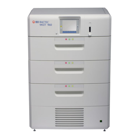
BD BACTEC FX User manual

BACTEC™ FX
Instrument User’s Manual
Becton, Dickinson and Company
7 Loveton Circle
Sparks, MD 21152 USA
Benex Limited
Pottery Road, Dun Laoghaire
Co. Dublin, Ireland
Australian Sponsor:
Becton Dickinson Pty Ltd.
4 Research Park Drive
Macquarie University Research Park
North Ryde, NSW 2113 Australia
8005110(09) 2019-09
441427
English
bd.com/e-labeling
KEY-CODE: 8005110
RxOnly

BD BACTEC™ FX Instrument User’s Manual
2
Change History
BD, the BD Logo, BACTEC, EpiCenter, Modem, and Synapsys are trademarks of Becton, Dickinson and
Company or its affiliates. © 2019 BD. All rights reserved.
No part of this publication may be reproduced, transmitted, transcribed, stored in retrieval systems, or
translated into any language or computer language, in any form or by any means, electronic, mechanical,
magnetic, optical, chemical, manual, or otherwise, without the prior written permission of BD, 7 Loveton
Circle, Sparks, MD, 21152, USA.
Revision Pages/Sections Reason
(07) 1, 2, 5, 6, 8, 9, 10, 11, 12
Deleted List of Figures. Deleted Manual
Structure section. Updated Use of this Manual
section. Removed Summary of Cautions and
Warnings section. References to Appendix, or
Appendices, were changed to Sections. Added
Preventative Maintenance statement to
Maintenance section. Updated user interface
descriptions.
Revision Date Change Summary
08 2019-03
Added new product information for Platelet
media types in the Introduction, Lab
Configuration, and Vial Operations sections.
09 2019-09
Converted printed instructions for use to
electronic format and added access information
to obtain the document from bd.com/e-labeling.
Added tabulated information on Vial Reentry
under Removing Positive, Negative and Ongoing
Vials section.

3
Table of Contents
1 –Introduction..................................................................................................................9
1.1 Intended Use............................................................................................................................... 9
1.2 Principles of the Procedure ......................................................................................................... 9
1.3 System Overview ...................................................................................................................... 11
1.3.1 Instrument Overview ................................................................................................... 11
1.3.2 Control Electronics...................................................................................................... 12
1.3.3 Incubation Subsystem................................................................................................. 13
1.3.4 Vial Agitation ............................................................................................................... 13
1.3.5 Measurement Subsystem ........................................................................................... 13
1.3.6 Vial Presence Sensing................................................................................................ 13
1.3.7 Station Indicators ........................................................................................................ 13
1.3.8 LCD and Touchscreen ................................................................................................ 13
1.3.9 USB Port/Flash Drive.................................................................................................. 13
1.3.10 Audible Alarm.............................................................................................................. 13
1.3.11 Barcode Scanners ...................................................................................................... 14
1.3.12 Software and Operation Overview .............................................................................. 14
1.3.13 Media Overview .......................................................................................................... 15
1.3.14 Built-In Test................................................................................................................. 16
1.3.15 Testing Overview ........................................................................................................ 16
1.4 Use of this Manual .................................................................................................................... 16
1.5 Conventions .............................................................................................................................. 17
1.5.1 User Interface .............................................................................................................17
1.5.2 Symbols and Connections Used on the Equipment.................................................... 17
1.5.3 Notes, Cautions, and Warnings .................................................................................. 19
2 –Installation .................................................................................................................21
2.1 General ..................................................................................................................................... 21
2.2 Instrument Specifications .......................................................................................................... 23
2.3 Instrument Installation ............................................................................................................... 24
2.3.1 Site Preparation .......................................................................................................... 24
2.4 Software Setup.......................................................................................................................... 25
2.4.1 Lab Configuration........................................................................................................ 26
2.4.2 Reports Configuration ................................................................................................. 30
2.4.3 Instr(ument) Configuration .......................................................................................... 32
2.4.4 LIS Configuration ........................................................................................................ 33
2.4.5 Time Configuration...................................................................................................... 38

BD BACTEC™ FX Instrument User’s Manual
4
3 – Controls and Indicators ............................................................................................ 41
3.1 General ..................................................................................................................................... 41
3.2 Power Switch ............................................................................................................................ 43
3.2.1 Location ...................................................................................................................... 43
3.2.2 Operation .................................................................................................................... 43
3.3 System Indicators...................................................................................................................... 44
3.3.1 Location ...................................................................................................................... 44
3.3.2 Indication..................................................................................................................... 44
3.4 Drawer Handles ........................................................................................................................ 45
3.4.1 Location ...................................................................................................................... 45
3.4.2 Operation .................................................................................................................... 45
3.5 Barcode Scanner ...................................................................................................................... 45
3.5.1 Location ...................................................................................................................... 45
3.5.2 Operation .................................................................................................................... 45
3.6 LCD/Touchscreen ..................................................................................................................... 46
3.6.1 Location ...................................................................................................................... 46
3.6.2 Operation .................................................................................................................... 46
3.7 Station Indicators ...................................................................................................................... 47
3.7.1 Location ...................................................................................................................... 47
3.7.2 Indication..................................................................................................................... 47
3.8 USB Ports ................................................................................................................................. 48
3.9 Audible Tones and Alarms ........................................................................................................ 48
3.10 Onscreen Keyboard .................................................................................................................. 48
3.11 Digital Thermometer.................................................................................................................. 49
3.12 Remote Alarm ........................................................................................................................... 51
3.13 Printer........................................................................................................................................ 51
4 –Operation................................................................................................................... 53
4.1 General ..................................................................................................................................... 53
4.2 Using the Instrument ................................................................................................................. 53
4.2.1 Touchscreen, Fields, and Buttons .............................................................................. 53
4.2.2 Status Display .............................................................................................................54
4.2.3 Instrument and Drawer Layout.................................................................................... 55
4.2.4 Vial and Station Statuses and States.......................................................................... 55
4.3 Daily Maintenance..................................................................................................................... 59
4.4 Collecting and Preparing Specimens ........................................................................................ 60
4.5 Entering Vials ............................................................................................................................ 61

Contents
5
4.6 Recalling, Entering, and Modifying Data ................................................................................... 64
4.6.1 General ....................................................................................................................... 64
4.6.2 Vial Data ..................................................................................................................... 64
4.6.3 Specimen Data ........................................................................................................... 66
4.6.4 Patient Data ................................................................................................................ 68
4.7 Testing Vials.............................................................................................................................. 70
4.8 Printing Reports ........................................................................................................................ 70
4.9 Removing Positive, Negative, and Ongoing Vials ..................................................................... 71
4.10 Responding to Alarms and Errors .............................................................................................76
4.11 Power Failures .......................................................................................................................... 76
4.12 Operation with a BD EpiCenter System .................................................................................... 76
4.12.1 Normal Operations...................................................................................................... 76
4.12.2 Isolation Mode............................................................................................................. 78
4.12.3 Degraded Mode Operations........................................................................................ 80
5 – Reference.................................................................................................................83
5.1 General ..................................................................................................................................... 83
5.2 Software Tree............................................................................................................................ 83
5.3 Status Display ........................................................................................................................... 84
5.3.1 Positive Removal Display ........................................................................................... 86
5.3.2 Negative Removal Display .......................................................................................... 88
5.3.3 ID(entify) Anonymous Display..................................................................................... 90
5.3.4 Vial Entry Display........................................................................................................ 92
5.3.5 System Alerts Display ................................................................................................. 95
5.3.6 Drawer View Display................................................................................................... 97
5.3.7 Culture – Patient Display ............................................................................................ 99
5.3.8 Culture – Specimen Display...................................................................................... 101
5.3.9 Culture – Vial Display................................................................................................ 104
5.3.10 Plot Display ............................................................................................................... 107
5.4 Reports Menu.......................................................................................................................... 109
5.4.1 Affected Vials ............................................................................................................ 111
5.4.2 Alert List .................................................................................................................... 113
5.4.3 Contaminant Vials..................................................................................................... 114
5.4.4 Culture Summary ...................................................................................................... 115
5.4.5 Current Inventory ...................................................................................................... 117
5.4.6 Current Negatives Report ......................................................................................... 119
5.4.7 Current Positives Report........................................................................................... 121
5.4.8 Loaded Vials ............................................................................................................. 122
5.4.9 Maintenance QC ....................................................................................................... 124
5.4.10 No Growth Accession ............................................................................................... 126
5.4.11 Orphan Vials ............................................................................................................. 127
5.4.12 Partially Seated Stations........................................................................................... 129

BD BACTEC™ FX Instrument User’s Manual
6
5.4.13 Pending..................................................................................................................... 131
5.4.14 Unloaded Negative Vials........................................................................................... 133
5.4.15 Unloaded Positive Vials ............................................................................................ 135
5.4.16 Unloaded Vials.......................................................................................................... 136
5.5 Maintenance............................................................................................................................ 138
5.5.1 Test Display .............................................................................................................. 138
5.5.2 Block/Unblock Stations Display ................................................................................ 140
5.5.3 Utilities Display..........................................................................................................141
5.5.3.1 Upgrade Software ..................................................................................... 142
5.5.3.2 Save DB and Log ...................................................................................... 142
5.5.3.3 Save Log ................................................................................................... 142
5.5.3.4 Reboot....................................................................................................... 142
5.5.3.5 Change Password ..................................................................................... 142
5.5.3.6 BD Utilities................................................................................................. 143
5.6 Configuration........................................................................................................................... 143
5.6.1 Lab ............................................................................................................................ 143
5.6.2 Reports Display......................................................................................................... 143
5.6.3 Instrument Display .................................................................................................... 143
5.6.4 LIS Display................................................................................................................143
5.6.5 Time .......................................................................................................................... 143
6 – Maintenance........................................................................................................... 145
6.1 General ................................................................................................................................... 145
6.2 Routine Maintenance .............................................................................................................. 145
6.2.1 Daily Maintenance .................................................................................................... 145
6.2.2 As Needed Maintenance........................................................................................... 146
6.2.2.1 Blocking Stations....................................................................................... 146
6.2.2.2 Unblocking Stations................................................................................... 147
6.2.3 Cleaning Air Filters.................................................................................................... 147
6.2.4 Replacing Vial Barcode Labels ................................................................................. 151
6.2.5 Cleaning and Decontamination................................................................................. 152
6.3 Maintenance – Test................................................................................................................. 153
6.4 Maintenance – Utilities Menu .................................................................................................. 153
6.4.1 Upgrade Software ..................................................................................................... 154
6.4.2 Save DB and Log...................................................................................................... 154
6.4.3 Save Log...................................................................................................................155
6.4.4 Reboot ...................................................................................................................... 155
6.4.5 Change Password..................................................................................................... 155
6.4.6 BD Utilities ................................................................................................................ 155
7 – Troubleshooting...................................................................................................... 157
7.1 General: Instrument Service ................................................................................................... 157
7.2 Error/Alert Messages ............................................................................................................. 157

Contents
7
7.3 Unusable Stations, Affected Vials, and Partially
Seated Vials ............................................................................................................................ 179
7.3.1 General ..................................................................................................................... 179
7.3.2 Unusable Stations..................................................................................................... 179
7.3.3 Affected Vials ............................................................................................................ 181
7.3.4 Partially Seated Stations........................................................................................... 181
7.4 Barcode Scanner .................................................................................................................... 183
8 – Limited Warranty ....................................................................................................185
9 – Contacts .................................................................................................................187
10 – Replacement Parts ...............................................................................................189
11 – Glossary ...............................................................................................................191

BD BACTEC™ FX Instrument User’s Manual
8

9
1 – Introduction
1.1 Intended Use
The BD BACTEC™ FX instrument is designed for the rapid detection of bacteria and fungi in clinical
specimens, blood, and blood products. Samples are drawn from patients or bagged blood/blood
products and injected directly into BD BACTEC culture vials, which are placed into the instrument for
incubation and testing.
1.2 Principles of the Procedure
When microorganisms are present in culture vials, they metabolize nutrients in the culture medium,
releasing carbon dioxide into the medium. A dye in the sensor at the bottom of the vial reacts with
CO2. This modulates the amount of light that is absorbed by a fluorescent material in the sensor. A
photo detector at each station measures the level of fluorescence, which corresponds to the amount of
CO2released by organisms. Then the measurement is interpreted by the system according to
preprogrammed positivity parameters.
At system start-up, the onboard computer performs self-diagnostics and downloads operating
instructions to the drawer rows. Then the instrument(s) automatically begin testing. Light Emitting
Diodes (LEDs) behind the vials illuminate the rows, activating the vials’ fluorescent sensors. After a
warm-up period, the instrument’s photo detectors then take the readings. A test cycle of all rows is
completed every ten minutes. Positive cultures are immediately flagged by an indicator light on the
front of the instrument, an audible alarm, and are displayed on the LCD display.
When positive vials are identified, the lab technologist pulls them from the instrument for confirmation
of results, and for isolation and identification of the organism.

BD BACTEC™ FX Instrument User’s Manual
10
This is an example:
Figure 1-1 shows the growth and detection process.
Figure 1-1 – BD BACTEC FX Fluorescent Technology
Organism metabolic activity releases CO2...
LED
Photo
Detector
Test Readings
Positivity Analysis
Row Board
Positive Test Results
indicated multiple ways
Which reacts with dye in vial sensor.
Positive vial is announced by audible alert, onscreen
indications, and the Positive Vial system indicator.
And positivity analysis is performed.
Raw data from detector is analyzed by row board ...
Photo detector reads fluorescence.
LED activates fluorescent material in sensor.
Fluorescence is modulated by dye in the sensor.

1 – Introduction
11
1.3 System Overview
The BD BACTEC FX instrument provides the following major features:
• Modular instrument design permits flexibility to accommodate laboratory needs
• Sliding drawers provide increased vial density, saving laboratory floor space
• Graphical user interface with color display and touchscreen provides ease of use
• Real-time vial presence sensors located in each vial station provide immediate feedback on
vial insertion and removal from stations
• Agitation provides additional enhancement of organism growth and detection
• The ability to mix bacterial, fungal, and mycobacterial cultures within a module or system is
accomplished by varying the medium type
• Can be connected to a BD EpiCenter™ workstation for enhanced instrument reporting and
data management capabilities. Standalone instruments can be connected to a compatible
Laboratory Information System (LIS).
1.3.1 Instrument Overview
The BD BACTEC FX instrument is an automated system for detecting the presence of microorganisms
in clinical samples, blood, and blood products. Inoculated vials are placed in one of the drawers in the
instrument, each of which contains a 10 x 10 array of vial stations. When the drawers are closed, vials
in protocol are monitored for microbial metabolic activity over time by measuring the fluorescence
levels from a specially designed sensor in the vial. This is performed by the measurement subsystem.
The algorithm subsystem analyzes the signals from the measurement subsystem to determine if
evidence of microbial growth (i.e. positivity) is present. Agitation is performed by the agitation
subsystem, which enhances organism growth. Data storage and examination is managed through a
data management subsystem. Stations are rendered unusable due to an alert condition such as an
incubation failure, agitation failure, or measurement system failure.
The user interface subsystem encompasses all instrument functions pertaining to instrument workflow,
primarily inserting vials into the instrument for testing, and subsequent removal of positive and final
negative vials. Demographic information can be entered into the system and reported out. Vial
information can be entered via a barcode reader, designed for one-handed operation, or can be
entered manually via an onscreen keyboard. Vials are associated to a particular station by the process
of inserting the vial into a station immediately after scanning the vial; this activates the station’s vial
presence sensor. You can view information about vials processed by the instrument, request printed
reports, or communicate with a BD EpiCenter system. Indicator LEDs on the front of the instrument
and others above each station convey status information. The instrument provides confirmatory audio
and visual feedback at the completion of each workflow transaction.
The instrument system has two basic configurations, a Single or a Stack. A Stack consists of a Top and
Bottom instrument. Multiple Stacks/Singles can be linked together with a BD EpiCenter system to
create a larger installation with full connectivity between modules. The measurement compartments of
the two instruments are identical, but the electronics bay of the Top instrument contains a display and
touchscreen and a computer and interface module which controls and collects data from both Top and
Bottom instruments. Both units contain a barcode scanner which is used to scan a unique sequence
number to identify the vial and the medium type, and a user applied (optional) accession label for
tracking specimens.

BD BACTEC™ FX Instrument User’s Manual
12
Figure 1-2 – BD BACTEC FX Instrument Stack and Single
1.3.2 Control Electronics
The instrument has several controllers that are responsible for control and analysis of the following:
• Temperature measurement and control
• Built-In-Test functions
• Agitation motor control
• Positivity analysis
• Illuminating station and system indicators
• Monitoring vial presence and door open sensors
• System communications
• User interface

1 – Introduction
13
1.3.3 Incubation Subsystem
The incubation subsystem is designed to maintain the temperature of the contents of any culture vial in
any station at 35.0 ± 1.5 °C. The temperature is achieved by forced air convection over the media vials.
Each drawer is a separately controlled incubation zone. Each zone contains blowers, heaters and
temperature sensors. The incubation system brings in a percentage of external make up air, monitors
the temperature of that air, and mixes it with a certain percentage of recirculating air. It then heats that
air according to the zone’s temperature setpoint and actual temperature measurements.
1.3.4 Vial Agitation
Vial stations are agitated so that their fluid contents achieve a homogeneous distribution of nutrients
and microbial by-products. Vials are arranged in separate row modules that are coupled by a gang
linkage to a motor. The motor causes each row module to agitate over a range of 0° to 20° relative to
horizontal.
1.3.5 Measurement Subsystem
The measurement subsystem activates the sensor in the bottom of a media vial optically. The
measurement consists of illuminating the sensor with an LED and collecting fluorescent light back from
the sensor with a photo detector. The collected data is processed, normalized and compensated for
thermal variation. Measurement is performed and processed by the Row Board.
1.3.6 Vial Presence Sensing
Each station has a vial presence sensor that immediately detects the insertion or removal of vials. This
allows users to place vials in any location, or to assign stations through Vial Entry. Station indicators
immediately reflect the changed status. Vial presence sensing is performed by the Row Board.
1.3.7 Station Indicators
LED indicators (shaped like crescents) located above vial stations indicate vial status and are
illuminated when a drawer is opened. Station indicators are controlled by the Row Board.
1.3.8 LCD and Touchscreen
The display is a 6.4" diagonal color Liquid Crystal Display. It is covered by a touchscreen that enables
you to perform actions and operations simply by touching buttons and fields shown on the screen.
1.3.9 USB Port/Flash Drive
Two standard USB ports are located behind the front bezel of the top (or Single) instrument. The front
ports are used primarily to save files to, and update system software from flash media.
1.3.10 Audible Alarm
An audible alarm provides notification of system alerts and positive vials. The default setting for the
audible alarm is 60 dB(A). The maximum setting is 85 dB(A). Loudness settings for positive vials are
set in the Configuration display and are indicated by numbers from 1 (softest) to 10 (loudest). A jack on
the rear of the instrument enables connection of an optional remote alarm unit.

BD BACTEC™ FX Instrument User’s Manual
14
1.3.11 Barcode Scanners
A barcode scanner is located on the mullion of each instrument. The scanner is designed to allow
one-handed vial barcode scanning by providing a bottle rest to assist in positioning and bottle rotation.
The barcode scanner is used to scan vial sequence and user-provided accession barcodes.
1.3.12 Software and Operation Overview
The Liquid Crystal Display (LCD) presents all the information needed to monitor instrument and station
status, to enter and remove vials, set up the instrument, print reports, and perform routine instrument
maintenance. The information is presented in the form of icons that graphically represent the
information (such as a clock to indicate the current time), text buttons, or a combination of icons and
text.
Operations you perform at the instrument can be initiated by opening a drawer and scanning a vial
(“vial activated workflow”) or can be initiated by selecting buttons, tabs, and fields on the LCD
touchscreen (“screen activated workflow”). Routine operations, such as entering vials and removing
positive vials, are initiated from the Status display. A Reports tab provides access to the built-in
BD BACTEC FX reports, while Maintenance and Configuration tabs provide access to these functions.
Positivity analysis (algorithm subsystem)
Algorithms determine vial positivity (i.e., the detection of microbial growth). Multiple algorithms are
used to test for vial positivity. Some algorithms are medium specific for greater sensitivity.
If a sequenced vial has not triggered a positivity algorithm by the end of the defined protocol
length, and there are no instrument error conditions that would prevent accurate detection of
positives, the vial is declared a negative vial, however, positivity algorithms continue to be applied
until the vial is removed from the instrument.
Database
The database maintains the test measurements for each vial, vial identification and association
data, and patient demographic information. Data is stored in the BD BACTEC FX database in both
standalone and BD EpiCenter configurations. In addition, associated instrument errors, and
operating conditions (e.g., test times, instrument temperature, etc.) are stored in the database.
The database stores vial results for up to 60 days after removal from the instrument (readings are
maintained for up to 14 days).
NOTE
Accepted barcode symbologies include Code 128, Codabar,
Code 39, and Interleaved 2 of 5.

1 – Introduction
15
1.3.13 Media Overview
Several media are available for use with the BD BACTEC FX system. These include:
BD BACTEC Standard/10 Aerobic /F
Recommended for 3.0 to 10.0 mL (8.0 to 10.0 mL optimal) blood volume.
BD BACTEC Plus Aerobic /F
Contains resins for antibiotic neutralization. Recommended for use in adult populations due to
higher blood volume capacity and resins. Recommended for 3.0 to 10.0 mL (8.0 to 10.0 mL
optimal) blood volume.
BD BACTEC Standard Anaerobic /F
Recommended for 3.0 to 7.0 mL (5.0 to 7.0 mL optimal) blood volume.
BD BACTEC Peds Plus /F
Optimized for use with pediatric patients and for low blood volume specimens. Recommended for
1.0 to 3.0 mL (range of 0.5 to 5.0 mL). Contains resins for antibiotic neutralization.
BD BACTEC Plus Anaerobic /F
Contains resins for antibiotic neutralization. Recommended for use in adult populations due to
higher blood volume capacity and resins. Recommended for 3.0 to 10.0 mL
(8.0 to 10.0 mL optimal) blood volume.
BD BACTEC Lytic/10 Anaerobic /F
Non-resin medium containing the blood lysing agent saponin. Provides improved time-to-detection
and recovery in comparison to standard anaerobic medium. The lysis of red cells provides
additional nutrients for microbial growth and reduced blood background. The lysis of white cells
releases phagocytized organisms. Recommended for 3.0 to 10.0 mL (8.0 to 10.0 mL optimal)
blood volume.
BD BACTEC Myco/F Lytic
Specialized medium for the detection of fungi and mycobacteria from blood and sterile body fluids.
Recommended for 1.0 to 5.0 mL (3.0 to 5.0 mL optimal) blood volume. A supplement may be
required for use with non-blood specimens.
BD BACTEC Mycosis IC /F
Selective culture medium specifically designed for the recovery of fungi from blood culture
specimens. Accepted specimen volume range is 3.0 to 10.0 mL. (This product is not for sale in
USA.)
BD BACTEC Platelet Aerobic/F
Recommended for 4.0 mL of platelets (Leukocyte Reduced Apheresis and Leukocyte Reduced
Whole Blood Concentrates).
BD BACTEC Platelet Anaerobic/F
Recommended for 4.0 mL of platelets (Leukocyte Reduced Apheresis and Leukocyte Reduced
Whole Blood Concentrates).
Each medium type has default test protocol duration (modifiable in the Lab Configuration display). The
default protocol can be overridden on each vial entered in the instrument.

BD BACTEC™ FX Instrument User’s Manual
16
1.3.14 Built-In Test
When power is first applied to the instrument, each of the major subsystems performs its native
built-in-test (BIT) to ensure proper operation. Any failure of a component test is considered a fatal error
for the measurement system, and no measurement cycles will be initiated.
1.3.15 Testing Overview
The instrument acquires light readings, temperature, and dark readings for each station of each
drawer once every 10 minutes. If a drawer is opened during the data acquisition cycle, the cycle is
aborted. When the drawer is closed the test cycle restarts after one minute.
After readings for stations are acquired, the instrument applies normalization to improve signal
accuracy, and temperature compensation to minimize the impact of temperature transients on data.
After normalization and temperature compensation, the instrument applies signal conditioning
algorithms to improve overall data quality.
Next, data for stations is tested for signal quality with a series of Built-In-Tests. These tests determine
whether data is to be used for positivity processing, and whether fault conditions exist in stations that
would render them unusable.
The final step in the testing process is the application of positivity algorithms to determine whether a
culture contains evidence of microbial growth. The instrument uses general positivity algorithms as
well as algorithms specific to each medium type to optimize positivity analysis.
1.4 Use of this Manual
This user's manual is designed as an integral part of instrument operation for technologists,
supervisors, and other personnel who operate and maintain the BD BACTEC FX instrument on a
regular basis. Every attempt has been made to include all information that would be required during
normal use and maintenance of the system. Should a question arise which is not answered in this
manual, please contact the following parties:
• Technical Information: In the United States contact BD Technical Service and Support at
1.800.638.8663 or bd.com.
• International contacts are listed in Section 9. Contact your local BD representative or bd.com.
Other documentation required for proper system operation includes:
BD BACTEC Media Package Inserts – These documents contain important information on the use,
storage, inoculation, performance, and limitations of each type of BD BACTEC medium. They are
included with each carton of media, and are available upon request from BD Technical Service and
Support.
BD EpiCenter System Help – The online Help utility provided with the BD EpiCenter system
provides comprehensive instructions on the operation of BD EpiCenter and the BD BACTEC FX
module within BD EpiCenter.

1 – Introduction
17
1.5 Conventions
1.5.1 User Interface
Screen buttons are shown in bold (e.g., select Save or select OK).
System prompts and messages are shown in a monospaced typeface (e.g., Report By does not
apply ).
Various displays are named in initial capital letters (e.g., Vial Entry display). Fields are shown as they
appear on the displays (e.g., Accession).
1.5.2 Symbols and Connections Used on the Equipment
The following symbols and connections are used on the BD BACTEC FX instrument:
Figure 1-3 – Front Connections
At center of photo, 9-pin serial connector (top); two USB connectors (middle); power switch (bottom).
Figure 1-4 – Top Rear Connections
Clockwise from top left: AC Power connector; USB connector; Network (BD EpiCenter) connector;
Stack connector; USB connector; Serial (LIS) connector; Remote Alarm connector

BD BACTEC™ FX Instrument User’s Manual
18
Figure 1-5 – Bottom Rear Connections
AC Power connector (top); Stack connector (bottom)
Figure 1-6 – Biohazard Symbol

1 – Introduction
19
1.5.3 Notes, Cautions, and Warnings
Throughout this manual, important information is presented in boxes offset from the regular text, and is
labeled as either a NOTE, CAUTION, or WARNING. These messages are formatted as shown below
and bear the following significance:
NOTE
Important information about instrument use worthy of special
attention is presented as a NOTE.
CAUTION
Information on an activity which potentially could cause damage
to the instrument is presented as a CAUTION.
WARNING
INFORMATION ON AN ACTIVITY WHICH POTENTIALLY COULD
CAUSE INJURY TO THE USER IS PRESENTED AS A WARNING.

BD BACTEC™ FX Instrument User’s Manual
20
Table of contents
Other BD Laboratory Equipment manuals
Popular Laboratory Equipment manuals by other brands

Safelab
Safelab Airone 1000RS/E instruction manual

New England BioLabs
New England BioLabs NEBNext Ultra II instruction manual

Grant
Grant SAP Series Service manual

horiba
horiba 7544 instruction manual

Accuris
Accuris SmartDoc 2.0 instruction manual

Agilent Technologies
Agilent Technologies 1100 Series Reference manual