Beale Street Audio P4-MB User manual

Beale Street Audio
P4-MB, P4-BB 4” In-Ceiling/In-Wall 2-Way Pancake
IPLCR4-MB, IPLCR4-BB Dual 4” LCR 2-Way Pancake
Ultra Shallow Depth Pancake Speakers
Installation Guide

2
Introduction
Congratulations and thank you for purchasing Beale Street Audio Pancake
speakers with Sonic Vortex®.
Why are they called Pancake Speakers? Because they not only produce a
delicious sound with a remarkably flat performance curve, but they are just
about as flat as a pancake with a less than three inch mounting depth.
Sonic Vortex incorporates a compact Integrated Transmission Line Ported
Enclosure. Most In Ceiling speakers do not utilize a back box, even fewer
have an enclosure, and only a Sonic Vortex speaker has an Integrated
Transmission Line Ported Enclosure. Without something behind the speaker
driver the music not only plays into the room, but also bleeds into adjoining
rooms such as the attic or an occupied room. The bleed negatively affects
performance, and sound consistency.
Sonic Vortex changes all that with its Transmission Line Ported Enclosure
that directs all of the sound from the speaker driver into the room it is
intend to be in, so you get to enjoy your speakers without disturbing the
rest of the house. Great bass response, stereo image, and big sound that
you can’t get with any other In Ceiling speaker.
Beale Street Audio Pancake speakers install with ease using the ‘dog’
mounting system and magnetic bezelless grilles for fast, clean installations.
Please follow the instructions in this manual to assure proper installation
and to achieve the full performance and satisfaction you would expect from
Beale Street Audio.
3
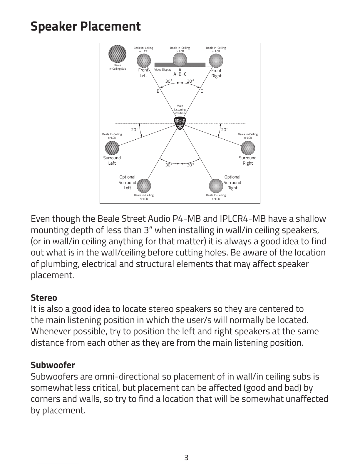
Speaker Placement
Even though the Beale Street Audio P4-MB and IPLCR4-MB have a shallow
mounting depth of less than 3” when installing in wall/in ceiling speakers,
(or in wall/in ceiling anything for that matter) it is always a good idea to find
out what is in the wall/ceiling before cutting holes. Be aware of the location
of plumbing, electrical and structural elements that may affect speaker
placement.
Stereo
It is also a good idea to locate stereo speakers so they are centered to
the main listening position in which the user/s will normally be located.
Whenever possible, try to position the left and right speakers at the same
distance from each other as they are from the main listening position.
Subwoofer
Subwoofers are omni-directional so placement of in wall/in ceiling subs is
somewhat less critical, but placement can be affected (good and bad) by
corners and walls, so try to find a location that will be somewhat unaffected
by placement.
Front
Left
Front
Right
Video Display
Beale In-Ceiling
or LCR
Beale
In-Ceiling Sub
Surround
Left
Surround
Right
Main
Listening
Position
Optional
Surround
Right
Optional
Surround
Left
30° 30°
30° 30°
20° 20°
A
B C
A=B=C
Beale In-Ceiling
or LCR
Beale In-Ceiling
or LCR
Beale In-Ceiling
or LCR
Beale In-Ceiling
or LCR
Beale In-Ceiling
or LCR
Beale In-Ceiling
or LCR
4
Angled
If using the ‘Angled In’ speakers, be sure to position them so the speakers
are facing into the room and directed toward the main listening position.
Surround
Locate surround speakers according to the recommendations in the
surround processor’s owner’s manual.
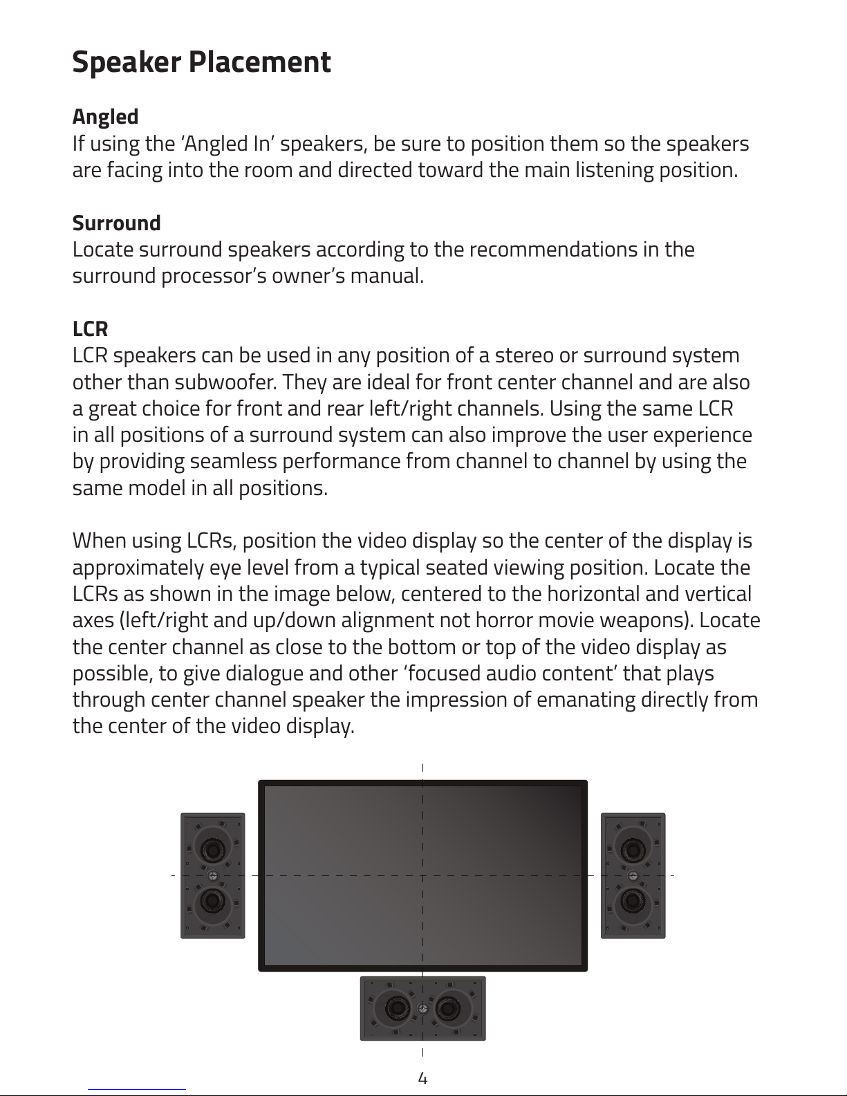
LCR
LCR speakers can be used in any position of a stereo or surround system
other than subwoofer. They are ideal for front center channel and are also
a great choice for front and rear left/right channels. Using the same LCR
in all positions of a surround system can also improve the user experience
by providing seamless performance from channel to channel by using the
same model in all positions.
When using LCRs, position the video display so the center of the display is
approximately eye level from a typical seated viewing position. Locate the
LCRs as shown in the image below, centered to the horizontal and vertical
axes (left/right and up/down alignment not horror movie weapons). Locate
the center channel as close to the bottom or top of the video display as
possible, to give dialogue and other ‘focused audio content’ that plays
through center channel speaker the impression of emanating directly from
the center of the video display.
Speaker Placement
5
Installation
SPEAKER WIRE
Pull one run of 16AWG stranded speaker wire from the amplifier location
to each speaker location. If in pre-wire, while the walls are open and it’s
easy, pull extra wire to any location that may be desirable to add speakers
at a later date. Leave extra length of wire on each end to allow making
connections and installing/removing speakers.
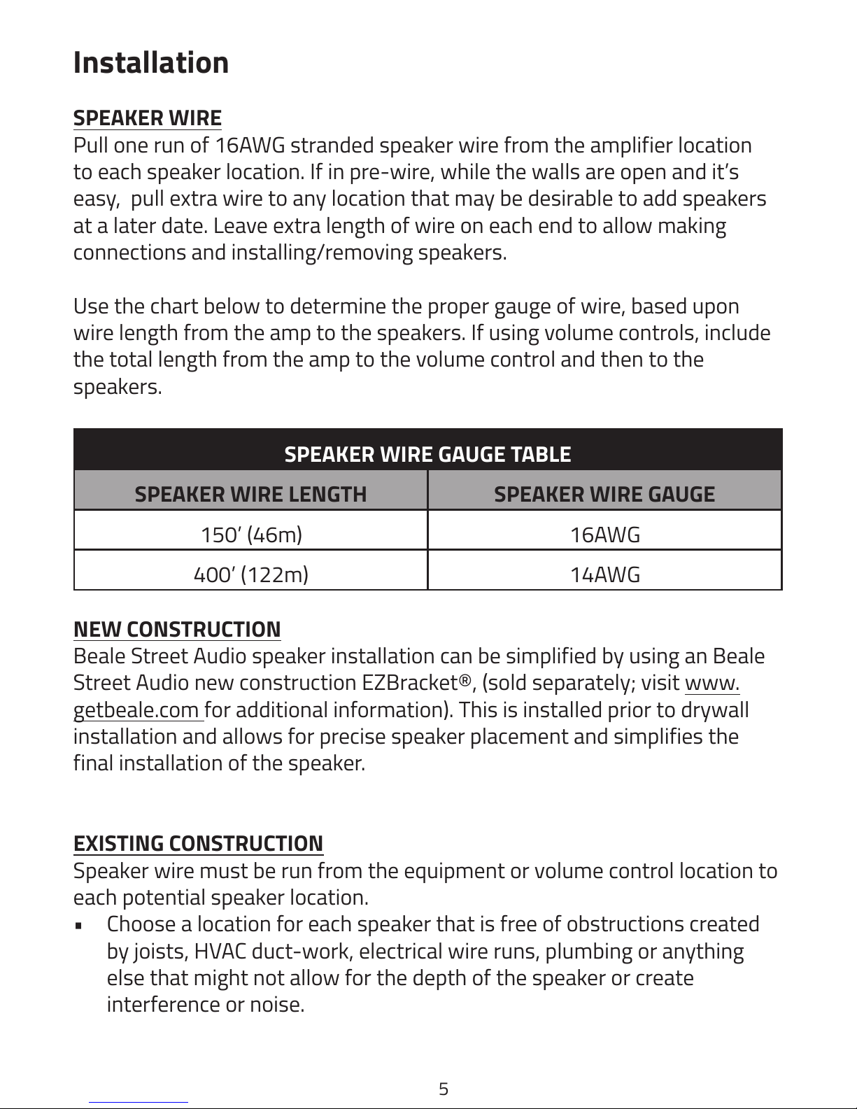
Use the chart below to determine the proper gauge of wire, based upon
wire length from the amp to the speakers. If using volume controls, include
the total length from the amp to the volume control and then to the
speakers.
SPEAKER WIRE GAUGE TABLE
SPEAKER WIRE LENGTH SPEAKER WIRE GAUGE
150’ (46m) 16AWG
400’ (122m) 14AWG
NEW CONSTRUCTION
Beale Street Audio speaker installation can be simplified by using an Beale
Street Audio new construction EZBracket®, (sold separately; visit www.
getbeale.com for additional information). This is installed prior to drywall
installation and allows for precise speaker placement and simplifies the
final installation of the speaker.
EXISTING CONSTRUCTION
Speaker wire must be run from the equipment or volume control location to
each potential speaker location.
• Choose a location for each speaker that is free of obstructions created
by joists, HVAC duct-work, electrical wire runs, plumbing or anything
else that might not allow for the depth of the speaker or create
interference or noise.
This manual suits for next models
3
Table of contents
Other Beale Street Audio Speakers manuals

Beale Street Audio
Beale Street Audio IWLCR4 Series User manual

Beale Street Audio
Beale Street Audio IC6-BSC User manual

Beale Street Audio
Beale Street Audio IC6-B User manual

Beale Street Audio
Beale Street Audio ICW4-MB User manual

Beale Street Audio
Beale Street Audio IC6-B User manual

Beale Street Audio
Beale Street Audio TIC651 User manual

Beale Street Audio
Beale Street Audio IW5-BSC User manual

Beale Street Audio
Beale Street Audio WP6V-BSC User manual

Beale Street Audio
Beale Street Audio Xpress BXCW401 User manual


