Beam 17R User manual

USER MANUAL
Table of Contents
Safety Information……………………………………………………...3
Specifications…………………………………………………………...4
Main Power Connection……………………………………………….5
DMX-512 Connection……………………………..…………………...5
Main Control Menu……………………………………………………..6
DMX Profile.....................................................................................8
Rigging the Fixture……………………………………………………10
Cleaning & Maintenance...............................................................11
Parts List.......................................................................................11


Check that the unit has not been damaged during transport
Protection Against Fire
1. Maintain a minimum of 1 foot distance from any type of flame.
3. Replace fuse only with the specified type and rating.
4. Do Not install the unit to close to a heat source.
5. Make sure cable are properly secured away from unit movement.
6. Maximum surface operating temperature 114º.
Protection Against Fire
1. Disconnect power before lamp replacement or servicing.
2. For connection to main power supply proceed to page 6.
3. This unit must be earthed. (electronically grounded)
4. Unit is IP rated 54 ( do not expose unit to high pressure water or submerge fixture).
Protection Against Mechanical Hazards
1. Use safety chain when hanging unit.
2. Use quality clamps or bolts when positioning unit
3. Do not open unit risk of electrical shock.
3

4
Specifications
Part Numbers
Fixture Lamp Flight Case
1300-O Beam 17R L-YODN 17R 1300-RC2 Dual Road Case
Mechanical Specifications
Fixture Packaged for Shipping
Size: 10.33” x 18.75” x 28.50”
Weight: 64 lb
Pan: 540° 8/16 Bit Tilt: 270° 8/16 Bit
DMX Connectors: Cable mounted 3-pin XLR connectors
Power Connectors: Weather seal Screw Type (Screw Type to Nema 5-
15 adapter included)
Thermal: Maximum ambient temperature 100° F
Maximum surface temperature 130° F
Fastening System: 2 Quick Release Clamp Mounts
Ip Rated: Ip44
Electrical Specifications
Power supply: Auto Switch100V-240V 50/60 HZ
Color Temp: 8000K
Power consumption: Amps 3.65
Watts 440
Ballast: Electronic
LAMP: YODN 1 7R lamp 330W
Display: LCD Display
18.75 ” ( with handles )
10.33 ”
7.5 ”
21 ”
28.50 ”
Prism: 8-Facet prism rotating in both directions at different speeds
Dimmer: Dual Blade dimming
Shutter: Mechanical Shutter strobe of lamp 13 flash per second
Frost: Mechanical Frost Effect
Focus: Mechanical Focus
Gobo: 17+Open bi-directional rotation Color: 14+Open bi-directional rotation
Electromechanical Effects
16 ”
Size: 24” x 16” x 34”
Weight: 76 lb
9.5 ”
5.75 ”

5
Main Power Connection
Caution!
1. Do not connect fixture to a dimmer system.
2. This unit must be earthed. (electronically grounded)
3. Replace fuse only with the specified type and rating.
The occupation of the connection-cable is as follows:
DMX-512 Connection
This device is equipped with a auto switching power supply that will allow you to work from 100V-240V 50/60Hz
The fixture is equipped with 3 pin XLR Cable mount for DMX input and output. The sockets are wired in parallel. Only
use a shielded twisted pair cable designed for RS-485 and 3 pin XLR plugs and connectors in order to connect the con-
troller with the fixture or the fixture with another.
Caution!
At the last fixture the DMX signal needs to be terminated with a terminator. Solder a
120 Ohm resistor between the (-) and the (+) signal into a 3 pin XLR plug and plug it
in to the last fixture on the signal run. Pre-manufactured terminator plugs are availa-
ble for purchase from your Mega-Lite dealer (P-DMX-T).
Cable (USA) Cable (EU) Pin 110V
Black Brown
White
Green
Light Blue
Yellow/Green
Live
Neutral
Ground
L
N
220V
L
L
DMX—input DMX—output
1. Shield
2. Signal (-)
3. Signal (+)
4. N/A
5. N/A
2
3
11
2
3
LN

6
Main Control
The control board on the fixture base is your interface to access and
control all the functions on the unit. Its LCD display gives you a code
view of the options and functions. The following will explain each func-
tion and its options.
Introduction
Press the ▲ and then press the Ok button then press ▲ to Access the setup menu
Setup Menu
001
Resetting
MENU
DMX
ERR
Set Manu Sys Advan
DMX Will operate using a DMX controller
Sound The light will activate it’s built in programs with sound activation
Demo The light will run built in programs
Run Mode
►Setting
Run Mode
DMX Address
Channel Mode
Demo Mode
Invert Pan
Invert Tilt
Swap Pan-Tilt
Encoder Pan-Tilt
No DMX Signal
Display
DMX
001
16CH
1
OFF
OFF
OFF
ON
KEEP
OFF
Press Ok use the ▲ or ▼ to select the desired DMX start Channel. Press Ok to confirm the setting. (DMX Channel must match the start
Channel setting in your DMX Controller)
DMX Address
Only One channel option 16Ch Mode available
Channel Mode
Press Ok use the ▲ or ▼ to select the desired preprogramed demo programs. Press Ok to confirm the setting. There are 9 programs to
chose from
Demo Mode
Run Mode
DMX Address
Channel Mode
Demo Mode
Invert Tilt
Swap Pan-Tilt
Encoder Pan-Tilt
DMX
001
16CH
1
OFF
OFF
ON
►Setting
Run Mode
DMX Address
Channel Mode
Demo Mode
Invert Pan
Invert Tilt
Swap Pan-Tilt
Encoder Pan-Tilt
No DMX Signal
Display
DMX
001
16CH
1
OFF
OFF
OFF
ON
KEEP
OFF
►Setting
Run Mode
DMX Address
Channel Mode
Demo Mode
Invert Pan
Invert Tilt
Swap Pan-Tilt
Encoder Pan-Tilt
No DMX Signal
Display
DMX
001
16CH
1
OFF
OFF
OFF
ON
KEEP
OFF
DOWN
UP
OK

This function allows you to invert the Pan via display command. Press Ok use the ▲ or ▼ to select Pan rotation configuration. Press OK to
confirm the setting .
Invert Pan
This function allows you to invert the Tilt via display command. Press Ok use the ▲ or ▼ to select Tilt rotation configuration. Press Ok to
confirm the setting .
Invert Tilt
This function will Swap the Pan Tilt channel on DMX control via display command. Press Ok use the ▲ or ▼ to select Swap the DMC channels
for the Pan & Tilt Press Ok to confirm the setting .
CH 1&2 Pan CH 3&4 Tilt =OFF
CH 1&2 Tilt CH 3&4 Pan =ON
Swap Pan-Tilt
This function will allow you to enable or disable the encoders for the Pan and Tilt. Press Ok use the ▲ or ▼ to select ON or OFF Press Ok to
confirm the setting .
(note) encoders are electronics that will reposition the unit if it’s manually moved.
Encoder Pan-Tilt
If DMX signal is removed or terminated the fixture will keep the last command or it will clear the command and place the fixture at 0 on all
channels. Press Ok use the ▲ or ▼ to select KEEP or CLEAR Press Ok to confirm the setting .
No DMX Signal
This command will allow you to select to leave the display permanently on when the fixture is on, or it will let you turn off the display after 30
seconds of not pressing the buttons. Press Ok use the ▲ or ▼ to select OFF or ON Press Ok to confirm the setting .
Display Power Save
Run Mode
DMX Address
Channel Mode
Demo Mode
Invert Tilt
Swap Pan-Tilt
Encoder Pan-Tilt
No DMX Signal
Display
DMX
001
16CH
1
OFF
OFF
ON
KEEP
OFF
Run Mode
DMX Address
Channel Mode
Demo Mode
Invert Tilt
Swap Pan-Tilt
Encoder Pan-Tilt
No DMX Signal
Display
DMX
001
16CH
1
OFF
OFF
ON
KEEP
OFF
Run Mode
DMX Address
Channel Mode
Demo Mode
Invert Tilt
Swap Pan-Tilt
Encoder Pan-Tilt
No DMX Signal
Display
DMX
001
16CH
1
OFF
OFF
ON
KEEP
OFF
Run Mode
DMX Address
Channel Mode
Demo Mode
Invert Tilt
Swap Pan-Tilt
Encoder Pan-Tilt
No DMX Signal
Display
DMX
001
16CH
1
OFF
OFF
ON
KEEP
OFF
Run Mode
DMX Address
Channel Mode
Demo Mode
Invert Tilt
Swap Pan-Tilt
Encoder Pan-Tilt
No DMX Signal
Display
DMX
001
16CH
1
OFF
OFF
ON
KEEP
OFF
Run Mode
DMX Address
Channel Mode
Demo Mode
Invert Tilt
Swap Pan-Tilt
Encoder Pan-Tilt
No DMX Signal
Display
DMX
001
16CH
1
OFF
OFF
ON
KEEP
OFF
This command will allow you to select whether the lamp will turn on after it receives power or to turn on the lamp only when it receives a DMX
command to do so. Press Ok use the ▲ or ▼ to select OFF or ON Press Ok to confirm the setting .
Lamp On @ Starting
Lamp on@Starting
Linear Color
Load Default
ON
OFF
►
This function will allow you to select whether the colors wheel will snap into color and bi-color or a continues control over any position of the
color wheel. Press Ok use the ▲ or ▼ to select OFF or ON Press Ok to confirm the setting .
Linear Color
Lamp on@Starting
Linear Color
Load Default
ON
OFF
►
This command will change the display command back to original factory settings. Press Ok then press Ok again to load to factory settings use
the ▲ or ▼ to cancel.
Load Default
Lamp on@Starting
Linear Color
Load Default
ON
OFF
►
7

8
DMX Profile
DMX Function Description Value Init Value
Open 0-4
White / Red 5-9
Red 10-14
Red / Orange 15-19
Orange 20-24
Orange / Aquamarine 25-29
Aquamarine 30-34
Aquamarine / Green 35-39
Green 40-44
Green / Lime Yellow 45-49
Lime Yellow 50-54
Lime Yellow / Lavender 55-59
Lavender 60-64
Lavender / Pink 65-69
1Color Pink 70-74 0
Pink / Yellow 75-79
Yellow 80-84
Yellow / Magenta 85-89
Magenta 90-94
Magenta / Cyan 95-99
Cyan 100-104
Cyan / CTO 260 105-109
CTO 260 110-114
CTO 260 / CTO 190 115-119
CTO 190 120-124
CTO 190 / CTB 8000 125-129
CTB 8000 130-134
CTB 8000 / Blue 135-139
Blue 140-144
Blue / White 145-149
Color Rotation (Slow to Fast) 128-255
Closed 0-3
Strobe (Slow to Fast) 4-103
Open 104-107
2Shutter Strobe Pulse (Slow to Fast) 108-207 255
Open 208-212
Random Strobe (Slow to Fast) 213-251
Open 252-255
3Dimmer Dimmer off to full 0-255 255

9
Open 0-3
Gobo 1 4-9
Gobo 2 10-14
Gobo 3 15-19
Gobo 4 20-24
Gobo 5 25-29
Gobo 6 30-34
Gobo 7 35-39
Gobo 8 40-44
Gobo 9 45-49
Gobo 10 50-54
Gobo 11 55-59
Gobo 12 60-64
Gobo 13 65-69
Gobo 14 70-74
Gobo 15 75-79
Gobo 16 80-84
Gobo 17 85-89
4Gobo Counter Clockwise Color Scroll (Fast to Slow) 90-129 0
Open 130-134
Clockwise Color Scroll (Slow to Fast) 135-170
Gobo 1 Shake (Slow to Fast) 171-175
Gobo 2 Shake (Slow to Fast) 176-180
Gobo 3 Shake (Slow to Fast) 181-185
Gobo 4 Shake (Slow to Fast) 186-190
Gobo 5 Shake (Slow to Fast) 191-195
Gobo 6 Shake (Slow to Fast) 196-200
Gobo 7 Shake (Slow to Fast) 201-205
Gobo 8 Shake (Slow to Fast) 206-210
Gobo 9 Shake (Slow to Fast) 211-215
Gobo 10 Shake (Slow to Fast) 216-220
Gobo 11 Shake (Slow to Fast) 221-225
Gobo 12 Shake (Slow to Fast) 226-230
Gobo 13 Shake (Slow to Fast) 231-235
Gobo 14 Shake (Slow to Fast) 236-240
Gobo 15 Shake (Slow to Fast) 241-245
Gobo 16 Shake (Slow to Fast) 246-250
Gobo 17 Shake (Slow to Fast) 251-255
5Prism No Function 0-127 0
Prism Engage 128-255
No Function 0-1
Prism Rotation 2-127
6Prism Rota- Counter Clockwise Prism Rotation (Fast to Slow) 128-190 0
Stop 191-192
Clockwise Prism Rotation (Slow to Fast) 193-255

Rigging the fixture
Caution!
1. The installations must be carried out by an authorized dealer or trained professional.
2. Unit may cause severe injures if you have doubts concerning the safety do not install.
3. Unit is to be 24inches away from flammable materials (decoration material)
4. Use high quality installation equipment to hang unit.
When rigging a unit it is very important that you follow common safety procedures. Rigging requires extensive experi-
ence including but not limited to calculating working loads, material being used and periodic safety inspections. If you
lack these qualifications, do not attempt the installation yourself, instead use a professional structural rigger.
When rigging the unit always be secured with a secondary safety attachment. The installation location of the projector
has got to be built in the way that it can hold 10 times the weight for 1 hour with out any harming. Installation should be
checked at least one time a year by a skilled person.
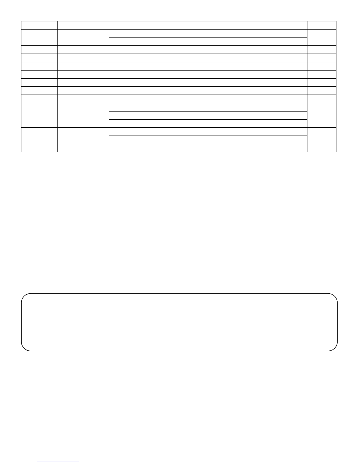
7No Function No Function 0-255 0
8Frost No Function 0-127 0
Frost (clear to frost) 128-255
9Focus Focus 0-255 0
10 Pan Pan Course 0-255 128
11 Pan Fine Pan Fine 0-255 128
12 Tilt Tilt Course 0-255 128
13 Tilt Fine Tilt Fine 0-255 128
14 Pan & Tilt Speed Pan & Tilt Speed (Fast to Slow) 0-255 0
No Function 0-26
15 Reset Lamp Reset 26-76 0
Pan Tilt Reset ]77-127
All Reset 128-255
No Function 0-9
16 Lamp Control Lamp OFF (hold for 3 seconds) 10-100 0
Lamp ON (hold for 3 seconds) 101-255
10

Cleaning and maintenance
Installation Maintenance: The operator has to make sure that the unit is operating safely and has the installa-
tions and electronics checked by an expert every 2 years.
The following points have to be considered during the inspection:
1) All screws used for installing the device or part of the device have to be tightly connected and must not be corroded.
2) There must not be any deformations on the housing, fixation and installation spots (ceiling, suspension, trussing).
3) Mechanically moved parts like axles and other must not show any traces of wearing and must not rotate with unbal-
ances.
4) The electronic power supply cables must not show any damages, material fatigue (e.g. porous cables) or sediments.
Further instructions depending on the installation spot and usage have to be adhered by a skilled installer and any
safety problems have to be removed.
Disconnect from mains before starting maintenance operation!
Caution Danger to life!
We recommend a frequent cleaning of the device. Please use a moist, lint free cloth. Never use alcohol or solvents!
1) The objective lens will require periodic cleaning on usage and environment. Environment with foggers will require
more periodic cleaning as fog fluid tends to build up residues, reducing the light output.
2) The cooling-fans should be cleaned monthly. DO NOT blow high pressure air into fans as incorrect rotation can
damage the fans operation.
3) The gobos, dichroic color filters and internal lenses may be cleaned with soft brush using soapy water.
4) The interior of the fixture should be cleaned using a vacuum.
5) We recommend proper lubrication of the motor wheel. The quantity of the oil must not be excessive in order to avoid
oil run outs when motor wheel rotates
Note: There is no serviceable parts inside the device except for the fuse. Maintenance and service operations
are to be carried out by authorized dealers.
Replacing the fuse: Only replace the fuse with the same type and rating.
Replacing the power cable: If the power cable of this device becomes damaged, it has to be replaced by author-
ized dealers only
Should you have further questions , please contact your dealer.
11
Parts List
1300-LDRI Lamp Driver Board
L-YOD17R Replacement Lamp YODN 17R
1300-FAN Rear Fan
1300-PCBD Display PCB
1300-RC2 2 Unit Road Case
1300-PCBM Main PCB
1300-PS Power Supply
1300-SEN1 Magnet Sensor
1300-SEN2 Optic Sensor
1300-PBEL Pan Belt
1300-QR Quick Release Clamp Mount
1300-MOTT Tilt Motor
1300-MOTF Focus Motor
1300-MOTG Gobo Motor
1300-MOTP Pan Motor
1300-MOTPR Prism Motor
1300-HAN Handel
1300-LENF Front Lens

Mega-Lite
18668 Highway 16N
Helotes, TX 78023
Ph 210-684-2600 Fax 210-855-6279
www.mega-lite.com / info@mega-lite.com
Warranty Information
Warranty Conditions
-Unless otherwise stated in writing, your product is covered by a one year parts and labor limited warranty.
-LEDs are not guaranteed to match in color temperature or output.
-It is the owner’s responsibility to furnish receipts or invoices for verification of purchase, date, and reseller or distributor.
If purchase date cannot be provided, date of manufacture will be used to determine warranty period.
-Goods returned under warranty must follow the proper authorization procedure and must be accompanied by a copy of
the original invoice.
-Goods repaired under warranty will be returned to the owner with the freight prepaid by MSI via the most economical
means of shipment.
-Repair or replacement as provided for under this warranty is the exclusive remedy of the consumer. MEGA SYSTEMS
INC. makes no warranties, express or implied, with respect to any product, and Mega Systems specifically disclaims any
warranty of merchantability or fitness for a particular purpose. Mega Systems shall not be liable for any indirect, inci-
dental or consequential damage, including lost profit, sustained or incurred in connection with any product or caused by
product defect or the partial or total failure of any product regardless of the form of action, weather in contract, tort
(including negligence), strict liability or otherwise, and weather or not such damage was foreseen or unforeseen.
- Warranty is void if the product is misused, damaged, modified in any way, or for unauthorized repairs or parts. This
warranty gives you specific legal rights, and you may also have other rights which vary from state to state.
Table of contents
Other Beam Lighting Equipment manuals
Popular Lighting Equipment manuals by other brands

Chauvet
Chauvet Mini Legend Wash DMX-427W user guide

Nicols
Nicols SKY 250 RB user manual

Federal Signal Corporation
Federal Signal Corporation Vitalite 121SLED Installation and maintenance instructions

American DJ
American DJ Comscan LED User instructions

ECOLOCITY
ECOLOCITY RL-SC-RS50 Connection guide

PASCO
PASCO WA-9897 instruction sheet