BEAMEX PGM User manual

© Copyright 2001, 2004, 2006, 2008
BEAMEX OY AB
Ristisuonraitti 10
FIN-68600 PIETARSAARI
FINLAND
Phone +358 - 10 - 5505000
Fax +358 - 10 - 5505404
Internet http://www.beamex.com
Beamex Inc
2270 NW Parkway
Suite 165
Marietta, GA 30067
U.S.A.
Phone 800 888-9892,
+1-770-951-1927
Fax +1-770-951-1928
Beamex Limited
Newtown Grange Farm Business Park
Desford Road
NEWTOWN UNTHANK
Leicestershire LE9 9FL
United Kingdom
Phone 01455 821 920
Fax 01455 821 923
Representative:
INSTRUCTION MANUAL
CALIBRATION PRESSURE PUMP
MODEL PGM
P
R
I
M
E
H
I
G
H
H Y D R A U L IC C A L I B R A T IO N P U M P
0 t o 7 0 0 b a r / 7 0 M P a / 1 0 0 0 0 p s i
M o d e
M A X I M U M O U T P U T P R E S S U R E 7 0 0 b a r
D o n o t p r e s s u ri z e g a s s r e s e r v o ir
A T IO N P U M P
/ 1 0 0 0 0 p s i
S S U R E 7 0 0 b a r
s s r e s e r v o i r
P
R
I
M
E
H
I
G
H
H Y D R A U L IC C A L I B R A T IO N P U M P
0 t o 7 0 0 b a r / 7 0 M P a / 1 0 0 0 0 p s i
M o d e
M A X I M U M O U T P U T P R E S S U R E 7 0 0 b a r
D o n o t p r e s s u ri z e g a s s r e s e r v o ir
P
R
I
M
E
H
I
G
H
H Y D R A U L IC C A L I B R A T IO N P U M P
0 t o 7 0 0 b a r / 7 0 M P a / 1 0 0 0 0 p s i
M o d e
M A X I M U M O U T P U T P R E S S U R E 7 0 0 b a r
D o n o t p r e s s u ri z e g a s s r e s e r v o ir
P
R
I
M
E
H
I
G
H
H Y D R A U L IC C A L I B R A T IO N P U M P
0 t o 7 0 0 b a r / 7 0 M P a / 1 0 0 0 0 p s i
M o d e
M A X I M U M O U T P U T P R E S S U R E 7 0 0 b a r
D o n o t p r e s s u ri z e g a s s r e s e r v o ir
P
R
I
M
E
H
I
G
H
H Y D R A U L IC C A L I B R A T IO N P U M P
0 t o 7 0 0 b a r / 7 0 M P a / 1 0 0 0 0 p s i
M o d e
M A X I M U M O U T P U T P R E S S U R E 7 0 0 b a r
D o n o t p r e s s u ri z e g a s s r e s e r v o ir
P
R
I
M
E
H
I
G
H
H Y D R A U L IC C A L I B R A T IO N P U M P
0 t o 7 0 0 b a r / 7 0 M P a / 1 0 0 0 0 p s i
M o d e
M A X I M U M O U T P U T P R E S S U R E 7 0 0 b a r
D o n o t p r e s s u ri z e g a s s r e s e r v o ir
P
R
I
M
E
H
I
G
H
H Y D R A U L IC C A L I B R A T IO N P U M P
0 t o 7 0 0 b a r / 7 0 M P a / 1 0 0 0 0 p s i
M o d e
M A X I M U M O U T P U T P R E S S U R E 7 0 0 b a r
D o n o t p r e s s u ri z e g a s s r e s e r v o ir
P
R
I
M
E
H
I
G
H
H Y D R A U L IC C A L I B R A T IO N P U M P
0 t o 7 0 0 b a r / 7 0 M P a / 1 0 0 0 0 p s i
M o d e
M A X I M U M O U T P U T P R E S S U R E 7 0 0 b a r
D o n o t p r e s s u ri z e g a s s r e s e r v o ir
P
R
I
M
E
H
I
G
H
H Y D R A U L IC C A L I B R A T IO N P U M P
0 t o 7 0 0 b a r / 7 0 M P a / 1 0 0 0 0 p s i
M o d e
M A X I M U M O U T P U T P R E S S U R E 7 0 0 b a r
D o n o t p r e s s u ri z e g a s s r e s e r v o ir
P
R
I
M
E
H
I
G
H
H Y D R A U L IC C A L I B R A T IO N P U M P
0 t o 7 0 0 b a r / 7 0 M P a / 1 0 0 0 0 p s i
M o d e
M A X I M U M O U T P U T P R E S S U R E 7 0 0 b a r
D o n o t p r e s s u ri z e g a s s r e s e r v o ir
P
R
I
M
E
H
I
G
H
H Y D R A U L IC C A L I B R A T IO N P U M P
0 t o 7 0 0 b a r / 7 0 M P a / 1 0 0 0 0 p s i
M o d e
M A X I M U M O U T P U T P R E S S U R E 7 0 0 b a r
D o n o t p r e s s u ri z e g a s s r e s e r v o ir
P
R
I
M
E
H
I
G
H
H Y D R A U L IC C A L I B R A T IO N P U M P
0 t o 7 0 0 b a r / 7 0 M P a / 1 0 0 0 0 p s i
M o d e
M A X I M U M O U T P U T P R E S S U R E 7 0 0 b a r
D o n o t p r e s s u ri z e g a s s r e s e r v o ir
P
R
I
M
E
H
I
G
H
H Y D R A U L IC C A L I B R A T IO N P U M P
0 t o 7 0 0 b a r / 7 0 M P a / 1 0 0 0 0 p s i
M o d e
M A X I M U M O U T P U T P R E S S U R E 7 0 0 b a r
D o n o t p r e s s u ri z e g a s s r e s e r v o ir
P
R
I
M
E
H
I
G
H
H Y D R A U L IC C A L I B R A T IO N P U M P
0 t o 7 0 0 b a r / 7 0 M P a / 1 0 0 0 0 p s i
M o d e
M A X I M U M O U T P U T P R E S S U R E 7 0 0 b a r
D o n o t p r e s s u ri z e g a s s r e s e r v o ir
P
R
I
M
E
H
I
G
H
H Y D R A U L IC C A L I B R A T IO N P U M P
0 t o 7 0 0 b a r / 7 0 M P a / 1 0 0 0 0 p s i
M o d e
M A X I M U M O U T P U T P R E S S U R E 7 0 0 b a r
D o n o t p r e s s u ri z e g a s s r e s e r v o ir
P
R
I
M
E
H
I
G
H
H Y D R A U L IC C A L I B R A T IO N P U M P
0 t o 7 0 0 b a r / 7 0 M P a / 1 0 0 0 0 p s i
M o d e
M A X I M U M O U T P U T P R E S S U R E 7 0 0 b a r
D o n o t p r e s s u ri z e g a s s r e s e r v o ir
P
R
I
M
E
H
I
G
H
H Y D R A U L IC C A L I B R A T IO N P U M P
0 t o 7 0 0 b a r / 7 0 M P a / 1 0 0 0 0 p s i
M o d e
M A X I M U M O U T P U T P R E S S U R E 7 0 0 b a r
D o n o t p r e s s u ri z e g a s s r e s e r v o ir

WARNINGS
Read the instruction manual carefully prior to setting up and using the
pressure pump. The pressure built up internally during use can be
very high.
Do not generate higher pressures than 20 bar (300 psig).
Higher pressures may damage the pump.
Only personnel with good experience and knowledge of high pressure
are allowed to work with the pressure pump. Incorrect use may result
in damage to the pump, the instrument connected to the pump and/or
personal injury.
Ensure that all connections are made correctly and that the hose and
the connectors are intact. Do not use faulty hoses or connectors.
Do not connect the pump to a high pressure source.
Use only the connectors provided with the pump. Impurities from
wrong materials may plug the pump.
Dear user,
We have made every effort to ensure the accuracy of the contents of this
manual. Should any errors be detected, we would greatly appreciate to re-
ceive suggestions to improve the quality of the contents of this manual.
The above not withstanding, we can assume no responsibility for any errors
in this manual or their eventual consequences.
We reserve rights to make modifications to this manual without any further
notice.
For more detailed technical data about the Calibration Pressure Pump,
model PGM, please contact the manufacturer.
8801300/UEPGM/000528
APPLICATION EXAMPLES
Pressure
instrument
T/C, Low V 4-w meas
R, RTD
3 & 4-w m eas
V,I, +24V IMEAS/SINK
V,HA RT®
Low V
MEAS& IOUTPUT
GEN
SENSOR M EAS URE & SIMU LA TE
ET E
T/C INT.RJ
T/C OR EXT
WIRESONLY
?
2
1
0
3
4
5
6
7
8
9
DCBA
2-w xmtr
MULTIFUNCTION CALIBRATOR Pressure
pump
Calibrator
06.10.2000 11:49
Input
Error
1.00
Output
Gauge
bar
8.0310
0.28 % of s pan
0.4982
+
0
-0% 50% 100%
Pressur e [P1: INT6C ]
Current [E: M eas]
mA
Pause Readings
Accept
Desired Inp ut Value 0.5000
T/C, Low V 4-w meas
R, RTD
3 & 4-w meas
V,I, +24V IMEAS/SINK
V,HA RT®
Low V
MEAS& IOUTPUT
GEN
SENSOR M EA SURE & SIM ULA TE
ET E
T / C IN T . R J
T/C OR EXT
WIRESONLY
?
2
1
0
3
4
5
6
7
8
9
DCBA
2-w xmtr
M UL T IF U N CT IO N C A L IB R A T O R Calibrator Pressure
pump
Pressure
instrument
06.10.2000 11:49
Input
Error
1.00
Output
Gauge
bar
8.0310
0.28 % of s pan
0.4982
+
0
-0% 50% 100%
Pressure [P1: INT6C]
C u rre n t [E : M e a s]
mA
Pause Readings
Accept
D es ire d In pu t V a lue 0.5 0 00
(plugged)

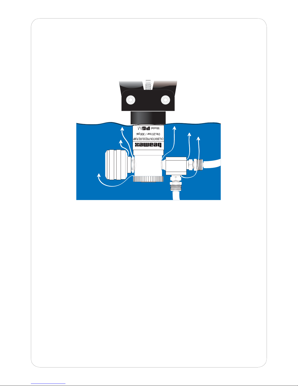
3.2 Leak Testing the Pump
If you suspect that the pump is leaking, immerse the top of the pressurized
pump in water. The most likely leakage points are shown in the following
picture. Where applicable, use sealant glue to stop the leakage.
V o u m e c o n n e c t o r
i s e a k i n g
V o u m e p i s t o n
s e a i s
e a k i n g
O u t p u t c o n n e c t o r
i s e a k i n g
V e n t v a v e
s e a i s e a k i n g
Note. Do not sink PGM any deeper than as shown in the picture. Otherwise
you might get water into the pump.
4 SPECIFICATIONS
Weight 0.4 kg approx. 0.9 lb
Dimensions Height 223 mm approx. 8
3/4"
Width 117 mm approx. 4 3/4"
Depth 38 mm approx. 1 1/2"
Pressure range 0 to 20 bar 0 to 300 psi
Pressure media Dry clean air or other clean, inert,
non-toxic, non-corrosive gases
Outlet connectors Two 1/8" NPT female.
CONTENTS
1 DESCRIPTION...................................................................................2
1.1 Standard Accessories ..................................................................2
1.2 Optional Accessories and Spare Parts.........................................2
2 OPERATION......................................................................................3
2.1 Practical Notes.............................................................................4
3 TROUBLESHOOTING/MAINTENANCE ...........................................4
3.1 Seal Replacement........................................................................4
3.1.1 Main Piston Seal.......................................................................5
3.1.2 Fine Control Seal ......................................................................5
3.1.3 Release Valve Seal...................................................................5
3.1.4 Replacing the Check Valve Seal...............................................5
3.2 Leak Testing the Pump ................................................................7
4 SPECIFICATIONS.............................................................................7
i

F i n e c o n t r o l
C o n n e c t o r s
f o r p r e s s u r e
m e a s u r e m e n t
h o s e s
M a i n p i s t o n h a n d l e s
R e l e a s e v a l v e
Screw for fastening
the cylinder block
Cylinder collar
1.5 mm hex screw
Fine control seal
Release valve seal
Check valve seal
Main piston lock ring
2.0 mm hex screw
Release valve stemRelease valve hand wheel
Main piston
NOTE! Using PGMwith seals not supplied by Beamex is at your own
risk. The warranty is no longer valid when using other seals
than the ones supplied by Beamex.
ch

3.1.1 Main Piston Seals
The main piston is assembled using special methods so it must be changed
as one component.
Remove the cylinder block from the main piston handles by opening the
three screws hidden under the cylinder collar. Rotate the cylinder unit until
the screws are visible one by one in the collar’s hole. When all screws are
loosened, pull the cylinder unit apart from the handle
Too loosen the piston, open the lock ring (see picture). Replace the piston
and reassemble.
3.1.2 Fine Control Seal
The variable volume is disassembled by opening the three 1.5 mm
hexagonal screws holding the retaining collar. Open the volume unit by
turning the knob counterclockwise.
After replacing the o-ring or after carrying out other reparative actions
grease the seal with pressure proof grease (e.g. Esso Nebula EP). When
reassembling, use a suitable sealant to avoid leakage (e.g. Locktite 572).
3.1.3 Release Valve Seal
Detach the release valve hand wheel from the release valve stem by
opening the 2 mm hexagonal screw. Turn the hand wheel upside down (the
stop pin pointing upwards) and fix it back to the release valve stem. Rotate
the had wheel counterclockwise to remove the release valve stem. Now the
release valve seal is visible.
Note that both the check valve spring and the check valve itself are
disassembled at the same time. Be careful not to damage or drop them
while replacing the release valve seal.
When reassembling, apply silicon oil on the vent valve stem and the
release valve seal.
3.1.4 Replacing the Check Valve Seal
The procedure is exactly the same as when replacing the release valve
seal (see the description above) but this time you also need to remove the
check valve spring and the check valve.
Replace the check valve seal, apply silicon oil and reassemble.
1 DESCRIPTION
The PGM calibration pressure pump is designed to manually generate
pressure up to 20 bar (300 psi) for quick and accurate calibration of
pressure gauges, transducers and other pressure measuring instruments.
1.1 Standard Accessories
The standard accessories are as follows:
∗Service seal kit for PGM.
∗Opening tool (hex wrench)
∗Output adapters:
•G 1/8” male 60°int. cone
•2 connectors for 1/8” ID hose
•2 connectors for 1/8” ID / 1/4" OD hose with nut
•Plug
∗This Instruction Manual.
2.2 Optional Accessories and Spare Parts
The optional accessories are as follows:
∗Carrying case
∗T-tubing set with connectors
∗1.5 m / 4.9” hose
∗Service seal kit for PGM.
gd

2 OPERATION
READ THE WARNINGS PRESENTED IN THIS MANUAL BEFORE
OPERATING THE PRESSURE PUMP.
1. Connect the instrument to be tested to the Pressure Measurement
Hose and attach it to the pump. Be sure that all the output connectors
are properly plugged or connected to an instrument to avoid leakage.
2. Adjust the fine control to "mid-travel".
3. Ensure the pressure release valve is closed (turn fully clockwise, but
keep in mind that excessive force may damage the seals).
4. Operate the handles several times to raise the pressure close to the
required value.
5. Do the final adjustment with the variable volume. If necessary, wait with
the adjustment until the temperature has stabilized (see chapter
2.1 Practical notes).
6. Repeat steps 4 and 5 until the highest calibration point is reached.
7. To decrease the pressure, open the release valve slightly.
Follow the decreasing of the pressure e.g. with the help of the
calibrator’s display. Close the release valve when the pressure is a little
above the required level.
8. Use the variable volume to set the exact pressure. Again, if necessary,
wait with the adjustment until the temperature has stabilized.
9. Repeat steps 7 and 8 until all of the decreasing calibration points are
done.
Small gauge pressures as well as negative pressures may be generated
using only the variable volume. The negative pressure is restricted to
approx. 150 mbar (then the force of the vacuum is equal to the force of the
volume piston’s spring).
2.1 Practical Notes
When increasing the pressure, the temperature of the air inside the system
rises on account of thermodynamic phenomena. When the temperature
returns to the level of the environment, the generated pressure may slightly
fall.
Respectively, when the pressure decreases, the air cools down. So when
the temperature again rises to the level of the environment, a slight in-
crease in the pressure may occur.
The temperature change depends (among other things) on the volume of
the system and the pressure change created by the user. Thus the effect of
the phenomenon varies for each calibration and even for each calibration
step.
Another phenomenom that affects the pressure is the flexibility of the hoses
used in the measurement system. When the pressure increases, the hoses
stretch, thus slightly altering the volume of the measurement system.
3 TROUBLESHOOTING/MAINTENANCE
If the pump assembly fails to indicate a pressure increase after consider-
able pumping action, the following items should be examined:
•Check to assure that the connections between the pump, the hose end
and the attached instrument(s) are tight and repeat operating instruc-
tions items 3 and 4. Check to assure that all the unused output connec-
tors are properly plugged.
If a pressure increase still cannot be obtained, it’s possible that one or more
of the seals and/or the check valve on the main piston is leaking and needs
to be replaced.
3.1 Seal Replacement
Depending on the frequency of use, the Main Piston Seals (and others) will
eventually need replacing. Although the replacement seals are an optional
accessory, the same instructions for fitting the seals are included in this
manual as in the replacement package.
fe

3.1.1 Main Piston Seals
The main piston is assembled using special methods so it must be changed
as one component.
Remove the cylinder block from the main piston handles by opening the
three screws hidden under the cylinder collar. Rotate the cylinder unit until
the screws are visible one by one in the collar’s hole. When all screws are
loosened, pull the cylinder unit apart from the handle
Too loosen the piston, open the lock ring (see picture). Replace the piston
and reassemble.
3.1.2 Fine Control Seal
The variable volume is disassembled by opening the three 1.5 mm
hexagonal screws holding the retaining collar. Open the volume unit by
turning the knob counterclockwise.
After replacing the o-ring or after carrying out other reparative actions
grease the seal with pressure proof grease (e.g. Esso Nebula EP). When
reassembling, use a suitable sealant to avoid leakage (e.g. Locktite 572).
3.1.3 Release Valve Seal
Detach the release valve hand wheel from the release valve stem by
opening the 2 mm hexagonal screw. Turn the hand wheel upside down (the
stop pin pointing upwards) and fix it back to the release valve stem. Rotate
the had wheel counterclockwise to remove the release valve stem. Now the
release valve seal is visible.
Note that both the check valve spring and the check valve itself are
disassembled at the same time. Be careful not to damage or drop them
while replacing the release valve seal.
When reassembling, apply silicon oil on the vent valve stem and the
release valve seal.
3.1.4 Replacing the Check Valve Seal
The procedure is exactly the same as when replacing the release valve
seal (see the description above) but this time you also need to remove the
check valve spring and the check valve.
Replace the check valve seal, apply silicon oil and reassemble.
1 DESCRIPTION
The PGM calibration pressure pump is designed to manually generate
pressure up to 20 bar (300 psi) for quick and accurate calibration of
pressure gauges, transducers and other pressure measuring instruments.
1.1 Standard Accessories
The standard accessories are as follows:
∗Service seal kit for PGM.
∗Opening tool (hex wrench)
∗Output adapters:
•G 1/8” male 60°int. cone
•2 connectors for 1/8” ID hose
•2 connectors for 1/8” ID / 1/4" OD hose with nut
•Plug
∗This Instruction Manual.
2.2 Optional Accessories and Spare Parts
The optional accessories are as follows:
∗Carrying case
∗T-tubing set with connectors
∗1.5 m / 4.9” hose
∗Service seal kit for PGM.
gd

F i n e c o n t r o l
C o n n e c t o r s
f o r p r e s s u r e
m e a s u r e m e n t
h o s e s
M a i n p i s t o n h a n d l e s
R e l e a s e v a l v e
Screw for fastening
the cylinder block
Cylinder collar
1.5 mm hex screw
Fine control seal
Release valve seal
Check valve seal
Main piston lock ring
2.0 mm hex screw
Release valve stemRelease valve hand wheel
Main piston
NOTE! Using PGMwith seals not supplied by Beamex is at your own
risk. The warranty is no longer valid when using other seals
than the ones supplied by Beamex.
ch
3.2 Leak Testing the Pump
If you suspect that the pump is leaking, immerse the top of the pressurized
pump in water. The most likely leakage points are shown in the following
picture. Where applicable, use sealant glue to stop the leakage.
V o u m e c o n n e c t o r
i s e a k i n g
V o u m e p i s t o n
s e a i s
e a k i n g
O u t p u t c o n n e c t o r
i s e a k i n g
V e n t v a v e
s e a i s e a k i n g
Note. Do not sink PGM any deeper than as shown in the picture. Otherwise
you might get water into the pump.
4 SPECIFICATIONS
Weight 0.4 kg approx. 0.9 lb
Dimensions Height 223 mm approx. 8
3/4"
Width 117 mm approx. 4 3/4"
Depth 38 mm approx. 1 1/2"
Pressure range 0 to 20 bar 0 to 300 psi
Pressure media Dry clean air or other clean, inert,
non-toxic, non-corrosive gases
Outlet connectors Two 1/8" NPT female.
CONTENTS
1 DESCRIPTION...................................................................................2
1.1 Standard Accessories ..................................................................2
1.2 Optional Accessories and Spare Parts.........................................2
2 OPERATION......................................................................................3
2.1 Practical Notes.............................................................................4
3 TROUBLESHOOTING/MAINTENANCE ...........................................4
3.1 Seal Replacement........................................................................4
3.1.1 Main Piston Seal.......................................................................5
3.1.2 Fine Control Seal ......................................................................5
3.1.3 Release Valve Seal...................................................................5
3.1.4 Replacing the Check Valve Seal...............................................5
3.2 Leak Testing the Pump ................................................................7
4 SPECIFICATIONS.............................................................................7
i

WARNINGS
Read the instruction manual carefully prior to setting up and using the
pressure pump. The pressure built up internally during use can be
very high.
Do not generate higher pressures than 20 bar (300 psig).
Higher pressures may damage the pump.
Only personnel with good experience and knowledge of high pressure
are allowed to work with the pressure pump. Incorrect use may result
in damage to the pump, the instrument connected to the pump and/or
personal injury.
Ensure that all connections are made correctly and that the hose and
the connectors are intact. Do not use faulty hoses or connectors.
Do not connect the pump to a high pressure source.
Use only the connectors provided with the pump. Impurities from
wrong materials may plug the pump.
Dear user,
We have made every effort to ensure the accuracy of the contents of this
manual. Should any errors be detected, we would greatly appreciate to re-
ceive suggestions to improve the quality of the contents of this manual.
The above not withstanding, we can assume no responsibility for any errors
in this manual or their eventual consequences.
We reserve rights to make modifications to this manual without any further
notice.
For more detailed technical data about the Calibration Pressure Pump,
model PGM, please contact the manufacturer.
8801300/UEPGM/000528
APPLICATION EXAMPLES
Pressure
instrument
T/C, Low V 4-w meas
R, RTD
3 & 4-w m eas
V,I, +24V IMEAS/SINK
V,HA RT®
Low V
MEAS& IOUTPUT
GEN
SENSOR M EAS URE & SIMU LA TE
ET E
T/C INT.RJ
T/C OR EXT
WIRESONLY
?
2
1
0
3
4
5
6
7
8
9
DCBA
2-w xmtr
MULTIFUNCTION CALIBRATOR Pressure
pump
Calibrator
06.10.2000 11:49
Input
Error
1.00
Output
Gauge
bar
8.0310
0.28 % of s pan
0.4982
+
0
-0% 50% 100%
Pressur e [P1: INT6C ]
Current [E: M eas]
mA
Pause Readings
Accept
Desired Inp ut Value 0.5000
T/C, Low V 4-w meas
R, RTD
3 & 4-w meas
V,I, +24V IMEAS/SINK
V,HA RT®
Low V
MEAS& IOUTPUT
GEN
SENSOR M EA SURE & SIM ULA TE
ET E
T / C IN T . R J
T/C OR EXT
WIRESONLY
?
2
1
0
3
4
5
6
7
8
9
DCBA
2-w xmtr
M UL T IF U N CT IO N C A L IB R A T O R Calibrator Pressure
pump
Pressure
instrument
06.10.2000 11:49
Input
Error
1.00
Output
Gauge
bar
8.0310
0.28 % of s pan
0.4982
+
0
-0% 50% 100%
Pressure [P1: INT6C]
C u rre n t [E : M e a s]
mA
Pause Readings
Accept
D es ire d In pu t V a lue 0.5 0 00
(plugged)
© Copyright 2001, 2004, 2006, 2008
BEAMEX OY AB
Ristisuonraitti 10
FIN-68600 PIETARSAARI
FINLAND
Phone +358 - 10 - 5505000
Fax +358 - 10 - 5505404
Internet http://www.beamex.com
Beamex Inc
2270 NW Parkway
Suite 165
Marietta, GA 30067
U.S.A.
Phone 800 888-9892,
+1-770-951-1927
Fax +1-770-951-1928
Beamex Limited
Newtown Grange Farm Business Park
Desford Road
NEWTOWN UNTHANK
Leicestershire LE9 9FL
United Kingdom
Phone 01455 821 920
Fax 01455 821 923
Representative:
INSTRUCTION MANUAL
CALIBRATION PRESSURE PUMP
MODEL PGM
P
R
I
M
E
H
I
G
H
H Y D R A U L IC C A L I B R A T IO N P U M P
0 t o 7 0 0 b a r / 7 0 M P a / 1 0 0 0 0 p s i
M o d e
M A X I M U M O U T P U T P R E S S U R E 7 0 0 b a r
D o n o t p r e s s u ri z e g a s s r e s e r v o ir
A T IO N P U M P
/ 1 0 0 0 0 p s i
S S U R E 7 0 0 b a r
s s r e s e r v o i r
P
R
I
M
E
H
I
G
H
H Y D R A U L IC C A L I B R A T IO N P U M P
0 t o 7 0 0 b a r / 7 0 M P a / 1 0 0 0 0 p s i
M o d e
M A X I M U M O U T P U T P R E S S U R E 7 0 0 b a r
D o n o t p r e s s u ri z e g a s s r e s e r v o ir
P
R
I
M
E
H
I
G
H
H Y D R A U L IC C A L I B R A T IO N P U M P
0 t o 7 0 0 b a r / 7 0 M P a / 1 0 0 0 0 p s i
M o d e
M A X I M U M O U T P U T P R E S S U R E 7 0 0 b a r
D o n o t p r e s s u ri z e g a s s r e s e r v o ir
P
R
I
M
E
H
I
G
H
H Y D R A U L IC C A L I B R A T IO N P U M P
0 t o 7 0 0 b a r / 7 0 M P a / 1 0 0 0 0 p s i
M o d e
M A X I M U M O U T P U T P R E S S U R E 7 0 0 b a r
D o n o t p r e s s u ri z e g a s s r e s e r v o ir
P
R
I
M
E
H
I
G
H
H Y D R A U L IC C A L I B R A T IO N P U M P
0 t o 7 0 0 b a r / 7 0 M P a / 1 0 0 0 0 p s i
M o d e
M A X I M U M O U T P U T P R E S S U R E 7 0 0 b a r
D o n o t p r e s s u ri z e g a s s r e s e r v o ir
P
R
I
M
E
H
I
G
H
H Y D R A U L IC C A L I B R A T IO N P U M P
0 t o 7 0 0 b a r / 7 0 M P a / 1 0 0 0 0 p s i
M o d e
M A X I M U M O U T P U T P R E S S U R E 7 0 0 b a r
D o n o t p r e s s u ri z e g a s s r e s e r v o ir
P
R
I
M
E
H
I
G
H
H Y D R A U L IC C A L I B R A T IO N P U M P
0 t o 7 0 0 b a r / 7 0 M P a / 1 0 0 0 0 p s i
M o d e
M A X I M U M O U T P U T P R E S S U R E 7 0 0 b a r
D o n o t p r e s s u ri z e g a s s r e s e r v o ir
P
R
I
M
E
H
I
G
H
H Y D R A U L IC C A L I B R A T IO N P U M P
0 t o 7 0 0 b a r / 7 0 M P a / 1 0 0 0 0 p s i
M o d e
M A X I M U M O U T P U T P R E S S U R E 7 0 0 b a r
D o n o t p r e s s u ri z e g a s s r e s e r v o ir
P
R
I
M
E
H
I
G
H
H Y D R A U L IC C A L I B R A T IO N P U M P
0 t o 7 0 0 b a r / 7 0 M P a / 1 0 0 0 0 p s i
M o d e
M A X I M U M O U T P U T P R E S S U R E 7 0 0 b a r
D o n o t p r e s s u ri z e g a s s r e s e r v o ir
P
R
I
M
E
H
I
G
H
H Y D R A U L IC C A L I B R A T IO N P U M P
0 t o 7 0 0 b a r / 7 0 M P a / 1 0 0 0 0 p s i
M o d e
M A X I M U M O U T P U T P R E S S U R E 7 0 0 b a r
D o n o t p r e s s u ri z e g a s s r e s e r v o ir
P
R
I
M
E
H
I
G
H
H Y D R A U L IC C A L I B R A T IO N P U M P
0 t o 7 0 0 b a r / 7 0 M P a / 1 0 0 0 0 p s i
M o d e
M A X I M U M O U T P U T P R E S S U R E 7 0 0 b a r
D o n o t p r e s s u ri z e g a s s r e s e r v o ir
P
R
I
M
E
H
I
G
H
H Y D R A U L IC C A L I B R A T IO N P U M P
0 t o 7 0 0 b a r / 7 0 M P a / 1 0 0 0 0 p s i
M o d e
M A X I M U M O U T P U T P R E S S U R E 7 0 0 b a r
D o n o t p r e s s u ri z e g a s s r e s e r v o ir
P
R
I
M
E
H
I
G
H
H Y D R A U L IC C A L I B R A T IO N P U M P
0 t o 7 0 0 b a r / 7 0 M P a / 1 0 0 0 0 p s i
M o d e
M A X I M U M O U T P U T P R E S S U R E 7 0 0 b a r
D o n o t p r e s s u ri z e g a s s r e s e r v o ir
P
R
I
M
E
H
I
G
H
H Y D R A U L IC C A L I B R A T IO N P U M P
0 t o 7 0 0 b a r / 7 0 M P a / 1 0 0 0 0 p s i
M o d e
M A X I M U M O U T P U T P R E S S U R E 7 0 0 b a r
D o n o t p r e s s u ri z e g a s s r e s e r v o ir
P
R
I
M
E
H
I
G
H
H Y D R A U L IC C A L I B R A T IO N P U M P
0 t o 7 0 0 b a r / 7 0 M P a / 1 0 0 0 0 p s i
M o d e
M A X I M U M O U T P U T P R E S S U R E 7 0 0 b a r
D o n o t p r e s s u ri z e g a s s r e s e r v o ir
P
R
I
M
E
H
I
G
H
H Y D R A U L IC C A L I B R A T IO N P U M P
0 t o 7 0 0 b a r / 7 0 M P a / 1 0 0 0 0 p s i
M o d e
M A X I M U M O U T P U T P R E S S U R E 7 0 0 b a r
D o n o t p r e s s u ri z e g a s s r e s e r v o ir
P
R
I
M
E
H
I
G
H
H Y D R A U L IC C A L I B R A T IO N P U M P
0 t o 7 0 0 b a r / 7 0 M P a / 1 0 0 0 0 p s i
M o d e
M A X I M U M O U T P U T P R E S S U R E 7 0 0 b a r
D o n o t p r e s s u ri z e g a s s r e s e r v o ir
Table of contents
Other BEAMEX Water Pump manuals


Popular Water Pump manuals by other brands

Alcatel
Alcatel 2033 instruction manual

GORMAN-RUPP PUMPS
GORMAN-RUPP PUMPS 81 2D11-B Installation, operation and maintenance manual

Batavia
Batavia MAXX Series operating instructions

North American Solar Solutions
North American Solar Solutions NASS 500 manual

Pentair
Pentair JUNG PUMPEN U3K /2 instruction manual

Homa
Homa C240W Original instruction manual


GORMAN-RUPP
GORMAN-RUPP PA6D60-4045T-SU Installation, operation and maintenance manual

Pompetravaini
Pompetravaini TCK Series INTEGRATIVE NOTES TO THE OPERATING MANUAL

BorMann
BorMann PRO BGB1000 user manual

WilTec
WilTec 50199-50220 Operation manual

Gardena
Gardena GP 3000/4 Operator's manual

Xylem
Xylem Flojet G55 Series Installation and operation manual