BEAMEX PGPH User manual
INSTRUCTION MANUAL
HIGH PRESSURE PNEUMATIC PUMP
MODEL PGPH


Dear user,
We have made every effort to ensure the accuracy of the contents
of this manual. Should any errors be detected, we would greatly ap-
preciate to receive suggestions to improve the quality of the contents
of this manual.
For more detailed technical data about the Instruction manual for
Beamex®PGPH High Pressure Pneumatic Pump, please contact the
manufacturer.
© Copyright 2013, 2015
BEAMEX OY AB
Ristisuonraitti 10
FIN-68600 Pietarsaari
FINLAND
Tel +358 - 10 - 5505000
Fax +358 - 10 - 5505404
Internet: http://www.beamex.com
8804400 / PGPHuEng / Version 1.1


CONTENTS
DESCRIPTION ............................................................................................. 1
Standard Accessories.........................................................................................1
Optional Accessories ..........................................................................................1
Connections and Parts........................................................................................2
Connection Diagram ...........................................................................................3
OPERATION.................................................................................................3
Keep in Mind.......................................................................................................4
TROUBLESHOOTING/MAINTENANCE .....................................................5
Seal Replacement...............................................................................................6
Cleaning the Pump..............................................................................................6
Leak Tests...........................................................................................................6
Leak Test for Positive Pressure..................................................................6
Leak Test for Negative Pressure (Vacuum)................................................6
SPECIFICATIONS........................................................................................7
The Pump Unit....................................................................................................7
Pressure Measurement Hoses (Optional Accessories).......................................8
Connections................................................................................................8
WARNINGS AND CAUTIONS .....................................................................9

Hose/connector
set for connect-
ing a calibrator's
high pressure
module to
PGPH
Hose/connector
set for connect-
ing the instru-
ment to be cali-
brated to PGPH
Connections when calibrating a transmitter using an internal pressure module.
Communication
cable.
Hose/connector
set for connect-
ing the instru-
ment to be cali-
brated to
PGPH.
Connections when calibrating a transmitter using an external pressure module.

1
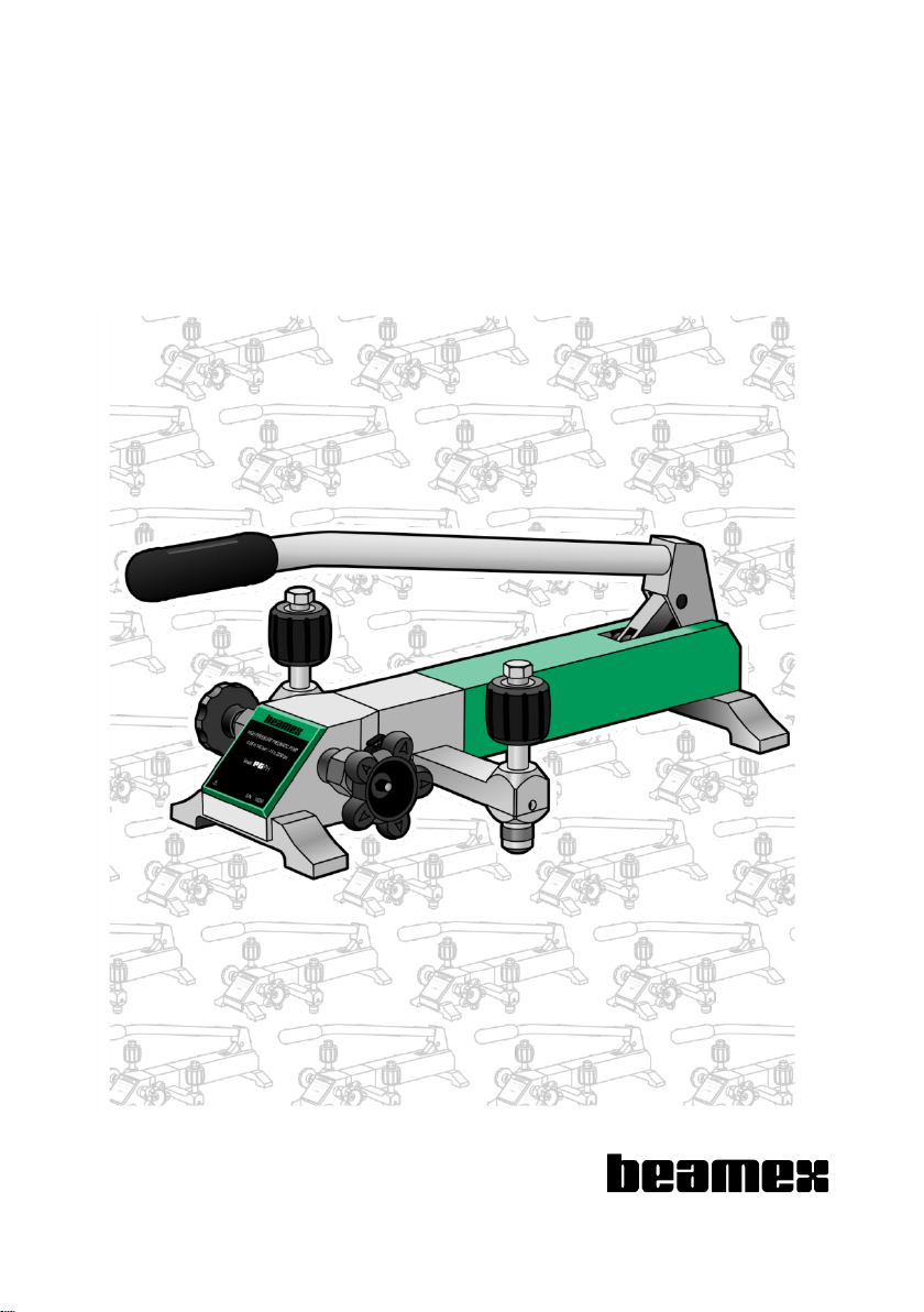
DESCRIPTION
The PGPH High Pressure Pneumatic Pump is designed to manually generate up to
140 bar (2000 psi) gauge pressure or up to -0.95 bar (-14 psi) vacuum for quick and
accurate calibration of pressure gauges, transducers and other pressure measure-
ment instruments.
Standard Accessories
The standard accessories are as follows:
One G ¼’’ (male) plug for Pressure connectors
A set of seals (o-rings), type: NBR70 for Pressure connectors (size 6 × 2).
Guarantee leaflet
This Instruction Manual
Optional Accessories
The optional accessories are as follows:
ITEM
ORDER CODE
Carrying case
8003315
Service seal kit
8003180
Tube of grease for the Fine Adjust stem
0005180
400 bar hose/connector set for connecting the instru-
ment to be calibrated to PGPH
8003380
400 bar hose/connector set for connecting a calibra-
tor's high pressure module to PGPH (*
8003365
*)Not needed when used high pressure module is an External Pressure Module (EXT).

2
Connections and Parts
Pump lever
Shut-off valve. Isolates the pump form the measurement circuit.
Release valve. Clockwise to close, anticlockwise to open.
Pressure connector, G ¼", for instrument / calibrator. Hand tightened.
Vent connection/hole
Fine Adjust handwheel. Rotating clockwise increases pressure.
Pressure connector, G ¼", for instrument / calibrator. Hand tightened.
Equivalent with Pressure connector
Pressure/Vacuum selector. Pull out for pressure and push in for vacuum.
Do not change when pressurized!
Selector lock
Pump body

3
Connection Diagram
Atmosphere
Pump
Shut-off valve
Release valve
Calibrator
(reference)
Fine Adjust
Instrument to be calibrated (DUT)
Pressure/Vacuum selector
OPERATION
Preparation
1. Select Pressure Mode .
2. Open Shut-off valve (counterclockwise) and Release valve.
3. Rotate Fine Adjust to mid position
4. Close Release valve
5. Connect instrument to be calibrated (Device Under Test, DUT) to Pressure con-
nector and the calibrator (pressure module, reference) to Pressure connector
. The location of the instrument and the calibrator may also be interchanged.
Pressure connectors and are equivalent. See also Leak Tests on page 6.
Calibration
6. Pump pressure/vacuum .
7. Close Shut-off valve (clockwise). See also notes further on.
8. Adjust pressure by rotating the Fine Adjust handwheel.
9. Repeat stages 6 to 8 until instrument's maximum pressure / deepest vacuum is
reached
When maximum pressure / deepest vacuum is reached continue as follows:
10.Gently open Release valve to release pressure/vacuum and close when ap-
proaching next calibration point.
11.Adjust pressure by rotating the Fine Adjust handwheel.
12.Repeat stages 10 and 11 until atmospheric pressure (or the instrument's meas-
urement span's pressure closest to atmospheric pressure) is reached.
End by opening Shut-off and Release valves. If you want to do several repeats,
restart from stage 3.

4
Keep in Mind
Immediately after a pressure change, the pressure may change slightly due to the
stretching/shrinking of the pressure measurement hose. Thermodynamic effects may
also cause pressure variation. In that case, adjust the pressure back to required value
using the Fine Adjust handwheel.
Do not exceed the max. operating pressure of the pump and the hose. Also observe
the pressure limit set by environmental conditions.
Ensure that there always is a reliable pressure indicator connected to the pump when
the pump is used.
If there is a strong counterforce while operating the pump lever, but no pressure
change is indicated, stop pumping and locate the fault. Always keep a reliable indi-
cator connected to the measurement system.
If the pump fails to indicate a pressure change after considerable pumping action of
the handle, check to assure that the connections between the pump, the hose end
and the attached instrument(s) are tight and retry pumping. Also check to assure that
all the unused output connectors are properly plugged.
If a pressure increase still cannot be obtained, it is possible that one or more of the
seals in the Pressure Pump is leaking and needs to be replaced.
Do not continue pumping if the functionality of the pump is not normal. Locate
the fault before you continue using the pump.
A full list of warnings is at the end of this manual.
5
TROUBLESHOOTING/MAINTENANCE
Hard to Pressurize Using Pressure Lever
CAUSES
SOLUTIONS
The Shut-off valve is not open.
Open the Shut-off valve .
Release valve is not closed.
Close the release valve .
The o-ring in Pressure connectors or
is missing, misplaced, or broken.
Replace the o-ring.
Pressure / Vacuum selector is in
wrong position.
Pressure: pull it out;
Vacuum: push it in.
Pipeline jamed with impurity.
Open the clean-out bolt at the bot-
tom of the pump and clean.
Hard to Fine Adjust Using Fine Adjust Valve
CAUSES
SOLUTIONS
The Shut-off valve is not closed.
Close the Shut-off valve .
Calibrator or instrument to be calibrated
is not connected tightly.
Check Pressure connectors and
. Re-tighten if necessary. Hand-
tightening should be sufficient.
The o-ring in Pressure connectors or
is missing, misplaced, or broken.
Replace the o-ring.
The end surface of the instrument's con-
nection thread is not smooth.
Use a PTFE washer in Pressure
connector.
The instrument's, calibrator's or hose's
thread does not match the thread on
PGPH's Pressure connectors or .
Use proper adapter.
Impurities inside the Fine Adjust volume
or connection.
Repeat pressurizing several times
and then release it suddenly, make
airflow bring the impurity out.
Hard to Turn the Valves or Handles
CAUSES
SOLUTIONS
Valve closed too tight after the previous
calibration.
Do not close shut off valves and
handles too tightly.
The new pump does not run smooth.
The new pump needs time to run in.
Lack of lubrication in threads.
Lubricate the thread.

6
Seal Replacement
Depending on the frequency of use, the main piston seals (and others) will eventually
need replacing. The replacement seals are part of an optional Service kit and the kit
includes instructions for replacing/fitting the seals.
Cleaning the Pump
PGPH has a plugged clean-out hole at the bottom of the pump. Open the plug and
remove any possible impurities inside the pump.
Leak Tests
If you want to test the pump and the connected measurement system, do as follows:
If you do not already have a calibration measurement system connected to the pump,
connect an accurate enough pressure measurement instrument, e.g. a Beamex
EXT250 pressure module to the pump. Plug any open connections.
You'll also need a clock to measure time.
Leak Test for Positive Pressure
Increase pressure using constant change rate up to pump's full scale positive pres-
sure (140 bar / 2000 psi). Start your clock.
After five minutes, record the pressure indication, p5.
After ten minutes, record the pressure indication, p10.
Calculate the leak, Lp, using this equation:
5
105
pppp
L
If Lpis less than 0.01 (1 %), the system is leak free.
Leak Test for Negative Pressure (Vacuum)
Decrease pressure using constant change rate down to pump's full scale negative
pressure (-0.95 bar / 95 kPa / -14.0 psi). Start your clock.
After five minutes, record the pressure indication, pv5.
After ten minutes, record the pressure indication, pv10.
Calculate the leak, Lv, using this equation: Lv= pv5 - pv10 [kPa].
If Lvis less than 1 kPa (approx. 0.14 psi), the system is leak free.

7
SPECIFICATIONS
The Pump Unit
Dimensions Pump lever down Pump lever up
Height 178 mm / 7" 506 mm / 20"
Length 540 mm / 21¼" 450 mm / 17¾"
Width 270 mm / 10½"
Weight 7.1 kg / 15.7 lb
Pressure range (* -0.95 bar /-14 psi to 140 bar / 2000 psi
Safety Pressure 180 bar / < 2600 psi
Relief Valve PGPH includes a built-in relief valve.
Pressure media Clean air
Temperature 0 ... 50 °C
Humidity < 85 %RH
Pressure resolution 0.1 mbar / 0.002 psi
Output connectors
Two G ¼" female connectors. One for the instrument to be calibrated and
another for the calibrator.
Clean-out connection: G ¼’’ female (plugged)
*)If local atmosphere pressure is 1 bar / 14.5 psi, the vacuum can reach to -0.95 bar / -14psi.
If local atmosphere pressure is P, the vacuum can reach to -0.95×P.

8
Pressure Measurement Hoses (Optional Accessories)
Length 1 m / 3 ft 3.3”
Internal diameter 2 mm / 0.08"
External diameter 5 mm / 0.2"
Operating pressure*@ 0°C (+32°F): 768 bar 76.8 MPa 11148 psi
@ 30°C (+86°F): 693 bar 69.3 MPa 10051 psi
@ 50°C (+122°F): 630 bar 63.0 MPa 9137 psi
@ 80°C (+176°F): 535 bar 53.5 MPa 7767 psi
@ 100°C (+212°F): 485 bar 48.5 MPa 7036 psi
@ 120°C (+248°F): 428 bar 42.8 MPa 6213 psi
Bursting pressure @ 20°C (68°F) 1950 bar 195.0 MPa 28200 psi
Operable temperature range -20 °C to +100 °C / -4 °F to +212 °F
Smallest bending radius 20 mm / 0.78"
below -20°C (-4°F) 30 mm / 1.18"
Connections
End connectors in 400 bar hose/connector set for connecting the instrument to be
calibrated to PGPH (Code 8003380):
PGPH end: G1/4" male
Instrument end: G 1/4" NPT male
End connectors in 400 bar hose/connector set for connecting a calibrator's high pres-
sure module to PGPH (Code 8003365):
PGPH end: G1/4" male
Calibrator / pressure module end: G1/8" male
Beamex reserves the right to make modifications to the specifications and this manual without
any further notice.

9
WARNINGS AND CAUTIONS
Read the instruction manual carefullyprior to setting up and using the pressure
pump. The pressure built up internally during use can be extremely high.
Only personnel with good experience and knowledge of high pressure media,
high pressure instruments and connections are allowed to work with the pres-
sure pump. Incorrect use may result in damage to the pump, the instrument
connected to the pump and/or personal injury.
Use eye shields. The built-in relief valve may blow nearby particles in random
directions.
Do not connect the pump to an external pressure source.
Vent external systems before connecting to the pump.
Ensure that all connections are made correctlyand that the hoses and connect-
ors are free of impurities and undamaged. Do not use faulty hoses or connect-
ors.
Use only measuring hoses provided by Beamex or other reliable suppliers. Ob-
serve the effect of the operational conditions to the maximum pressure allowed
in the hose. The specifications of Beamex hoses can be found on page 7 of this
manual.
The environmental conditions may restrict the allowable maximum pressure to
a lower level than the pump and the hose enable. In that case please consider
using a relief valve.
Always depressurize PGPH when it is left on its own.
Avoid possible damage when suddenly apply pressure to low pressure and
small chamber gauges.
Do not exceed the safety pressure limit (180 bar / < 2600 psi).
Compressed air may cause problem in explosive or corruptive environment.
Do not shift the pressure/vacuum selector to vacuum mode under pressure.
Do not over tighten connectors to avoid any damage.
Store the pump in the dry and non-corruptive environment.
If the pump is accidentally dropped, it may be damaged. Do not use the pump
before it is inspected at Beamex’s service.
Do not use PGPH in any other way than as described in this manual.
Any safety problems or damages caused by incorrect operation, are beyond
Beamex's responsibility.

BEAMEX OY AB
Ristisuonraitti 10
FIN-68600 PIETARSAARI
FINLAND
Phone +358 - 10 5505000
Fax +358 - 10 5505404
E-mail sales@beamex.com
Internet http://www.beamex.com
Beamex Inc
2152 NW Parkway
Suite A
Marietta, GA 30067
U.S.A.
Phone 800 888-9892,
+1-770-951-1927
Fax +1-770-951-1928
E-mail beamex.inc@beamex.com
Beamex Limited
Newtown Grange Farm Business Park
Desford Road
NEWTOWN UNTHANK
Leicestershire LE9 9FL
United Kingdom
Phone 01455 821 920
Fax 01455 821 923
E-mail beamex.ltd@beamex.com
Representative:
Table of contents
Other BEAMEX Water Pump manuals


Popular Water Pump manuals by other brands


Danfoss
Danfoss PAHT G Operation guide

Kärcher
Kärcher AT manual

Dover
Dover PSG WILDEN XPR460 Engineering, operation & maintenance

CRANE PUMPS & SYSTEMS
CRANE PUMPS & SYSTEMS DEMING 7365 Series Installation and operation manual

Pentair
Pentair DKG instruction manual

EINHELL
EINHELL GC-SP 5511 IF Original operating instructions

Pentair
Pentair WhisperFloXF Installation and user guide

York
York 4 SYK 2 Series manual

ProMinent
ProMinent alpha Series General operating instructions

Bühler technologies
Bühler technologies P4.3 Brief instructions

Maruyama
Maruyama MP2500E2 instruction manual

Ingersoll-Rand
Ingersoll-Rand PD10E-X-X user manual