BEAMEX PGC User manual

INSTRUCTION MANUAL
BEAMEX®PRESSURE/VACUUM
PUMP MODEL PGC


Dear user,
We have made every effort to ensure the accuracy of the contents
of this manual. Should any errors be detected, we would greatly ap-
preciate to receive suggestions to improve the quality of the contents
of this manual.
The above notwithstanding, we can assume no responsibility for any
errors in this manual or their eventual consequences.
We reserve rights to make modifications to this manual without any
further notice.
For more detailed technical data about the Instruction manual for
PGC Calibration Pressure Pump, please contact the manufacturer.
© 2016
BEAMEX OY AB
Ristisuonraitti 10
FIN-68600 Pietarsaari
FINLAND
Tel +358 - 10 - 5505000
Fax +358 - 10 - 5505404
Internet: http://www.beamex.com
8804900 / PGCuEng / Version 1

CONTENTS
DESCRIPTION ............................................................................................. 1
Standard Accessories.........................................................................................1
Optional Accessories ..........................................................................................1
USING THE PUMP.......................................................................................3
Preparation..........................................................................................................3
Operation (Pressure)...........................................................................................4
Operation (Vacuum)............................................................................................5
When Calibration is Done....................................................................................5
TROUBLESHOOTING/MAINTENANCE .....................................................6
Seal Replacement...............................................................................................6
SPECIFICATIONS........................................................................................ 8
The Pump Unit....................................................................................................8
The Pressure Measurement T-hose (Part of Pump Kit)......................................8
WARNINGS..................................................................................................9

1
DESCRIPTION
Beamex®PGC calibration pressure pump is designed to manually generate be-
tween -0.95 to 35 bar (approx. -13.7 to 510 psi) of vacuum and pressure for quick
and accurate calibration of pressure gauges, transducers and other pressure meas-
urement instruments.
Standard Accessories
The standard accessory for a stand-alone pump is:
This manual
Additionally, for a pump kit:
Connector kit:
●G 1/8’’ male, 60° internal cone / G 1/8’’ male + o-ring
to replace a Hydrotechnics®connector in Beamex®MC6 Calibrator's
internal high pressure modules.
●G 1/8’’ male, 60° internal cone / G 1/4’’ B female + 2 seals.
An adapter for connecting the pressure measurement T-hose to
Beamex' high pressure EXT modules.
●G 1/8’’ male, 60° internal cone / G 1/4’’ NPT male.
An adapter for connecting the pressure measurement T-hose to
the instrument to be calibrated (DUT).
40 bar measurement T-hose.
Carrying case.
Optional Accessories
The optional accessories are as follows:
Service seal kit containing a set of seals and gaskets.
For details, see picture on page 7.
Fine adjustment valve including relief valve and gaskets.
Upper part of pump (cylinder) including pressure/vacuum selector.
Bottom part including handles and piston.

2
Presenting PGC.
Device Under Test
(DUT)
Reference meas-
urement
Connection diagram when calibrating

3
USING THE PUMP
Preparation
Before applying pressure/vacuum, ensure that the pressure/vacuum selector is ac-
cording to your calibration needs. If not, check that the release valve is open, and
then use a small screw driver to change the setting of the pressure/vacuum selector.
IMPORTANT
Never change the pressure/vacuum selector's setting when there is
pressure or vacuum in the pump/system.
Please read all the warnings found on page 9.
Before doing the connections, check that the pressure hose is intact and the o-rings
in it are in place. Use only the pressure measurement T-hose delivered with the
pump. Also check that the pump is in working condition.
Use the pressure measurement T-hose to connect the Device Under Test (DUT) and
the reference (a calibrator with internal pressure modules or an external pressure
module communicating with a calibrator) to the pump. For help on connections, refer
to the adjacent connection diagram. Use hand tightening for the connections. Ensure
that the measurement range of the connected reference is appropriate.
Note.
It is not recommended to use the plugged connection on top of PGC. Further
information in warnings, presented on page 9.
Normally: Check that the thumb nut of the stroke length setting is approx. 1 centime-
ters from the lowermost position. If you for some reason need to reduce the volume
per stroke, raise the thumb nut to squeeze the spring. This can also be done during
the calibration run.
Turn the release valve clockwise to close it.
Continue either from chapter Operation (Pressure) on page 4 or Operation (Vac-
uum) on page 5.

4
Operation (Pressure)
Turn the fine adjustment valve counterclockwise until it is fully open. Approximately
halfway, if you do not need to use the full pressure range of the pump.
Pump to raise the pressureclose to the next calibration point. Use the fine adjustment
to raise the pressure to the calibration point.
Notes.
The maximum pumping pressure is approximately 25-30 bar. The rest of the
pressure is done using the fineadjustment valve. The total maximum pressure
value depends on the volume of the calibration circuit.
After increasing the pressure, the reading may slightly drop again for about 30
seconds. This is caused by thermodynamic effects, the tube connection and
the sealing gaskets. If the pressure does not come to a standstill, check the
measuring circuit for tightness.
When the calibration point with the highest pressure value is reached and there is no
need for calibration points with decreasing pressure, either
Open the release valve, close it and start a new calibration repeat, or
continue to chapter When Calibration is Done on page 5.
If there is need for calibration points with decreasing pressure, carefully open the
release valve to decrease the pressure. When getting close to the required pressure,
close the release valve and use the fine adjustment valve to lower the pressure to the
calibration point. Again, wait for approximately 30 seconds for the pressure to stabi-
lize.
When the last calibration point is done, either do another calibration run or continue
to chapter When Calibration is Done on page 5.
WARNINGS!
Do not exceed the max. operating pressure of the pump and the hose.
If there is a strong counterforce while operating the handles, but no pressure
increase is indicated, stop pumping and locate the fault. Always keep a reliable
indicator connected to the measurement system.
A full list of warnings is on page 9.

5
Operation (Vacuum)
Turn the fine adjustment valve clockwise until it is fully closed.
Pump to lower the pressure close to the next calibration point. Use the fine adjust-
ment to lower the pressure to the calibration point.
Notes.
After decreasing the pressure, the reading may slightly change for about 30
seconds. This is caused by thermodynamic effects, the tube connection and
the sealing gaskets. If the pressure does not come to a standstill, check the
measuring circuit for tightness.
When the calibration point with the lowest pressure value is reached and there is no
need for calibration points with increasing pressure, either
Open the release valve, close it and start a new calibration repeat, or
continue to chapter When Calibration is Done on page 5.
If there is need for calibration points with increasing pressure, carefully open the re-
lease valve to increase the pressure. When getting close to the required pressure,
close the release valve and use the fine adjustment valve to increase the pressure to
the calibration point. Again, wait for approximately 30 seconds for the pressure to
stabilize.
When the last calibration point is done, either do another calibration run or continue
to chapter When Calibration is Done on page 5.
When Calibration is Done
IMPORTANT!
Open the release valve to remove pressure/vacuum before disassem-
bling the measurement system.
Disassemble the measurement system and make sure the pump is left in a state that
allows easy start the next time the pump is used. (Release valve open, stroke length
set to maximum etc.)

6
TROUBLESHOOTING/MAINTENANCE
If the pump assembly fails to indicate a pressure increase/decrease after considera-
ble pumping action of the handle, check the following things:
Assure that the connections between the pump, the hose end and the at-
tached instrument(s) are tight and retry pumping.
Check that all the unused output connectors are properly plugged. Also
check that the release valve is closed.
Check that the pressure/vacuum selector is not left somewhere in between
pressure side and vacuum side. If so, push it in place as needed.
If a pressure increase/decrease still cannot be obtained, it’s possible that one or more
of the seals in the Pressure Pump is leaking and needs to be replaced.
If the test pump has not been used for a longer period of time, the first lift may be
somewhat sluggish. This effect will disappear again during further operation.
Do not continue pumping if the functionality of the pump is not normal. Lo-
cate the fault before you continue using the pump.
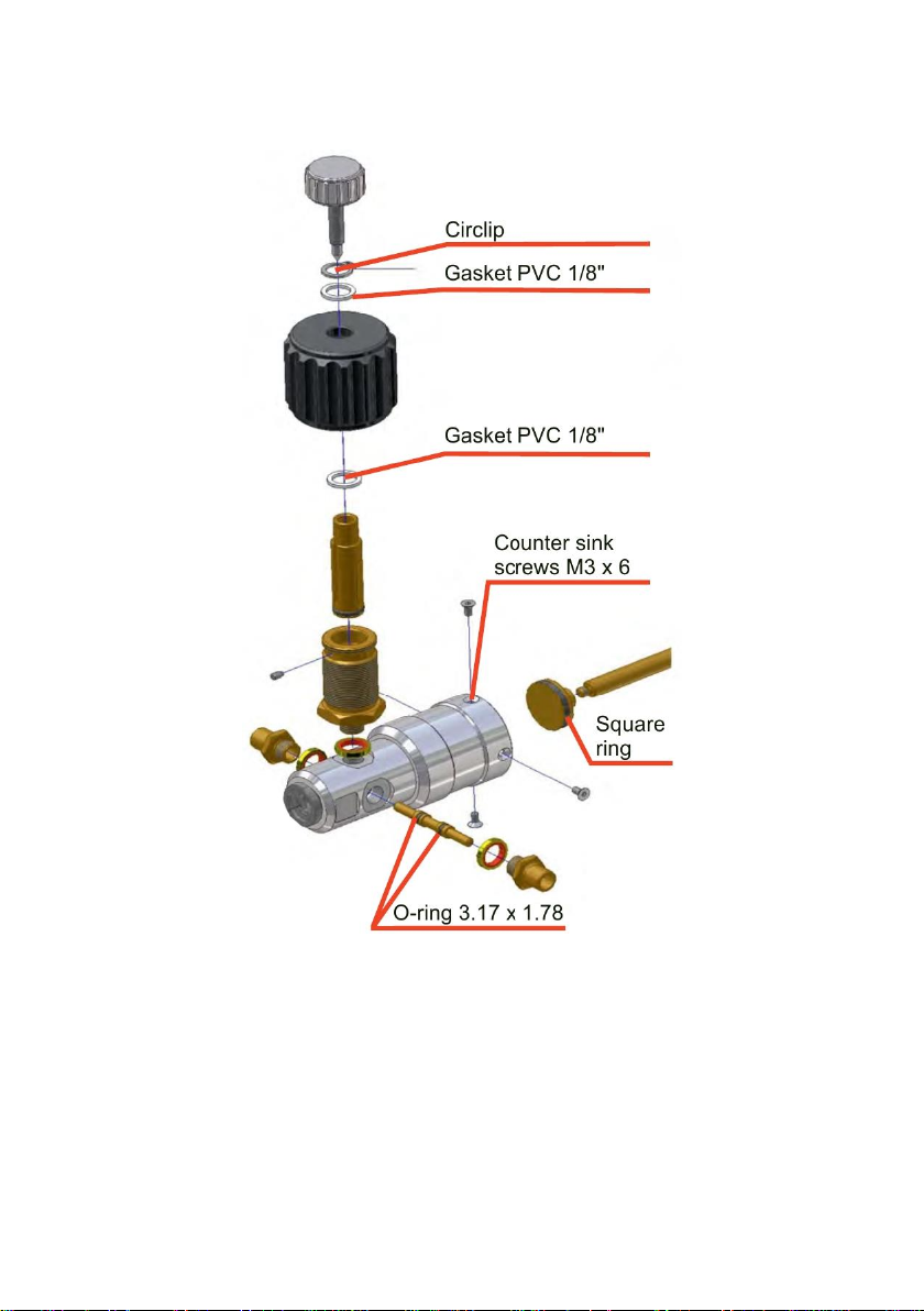
Seal Replacement
Depending on the frequency of use, the seals will eventually need replacing. The
replacement seals are an optional accessory, but the picture on next page presents
where the seals go.
7

8
SPECIFICATIONS
The Pump Unit
Weight 820 g 1.81 lb
Dimensions Height 220 mm approx. 8.7"
Width 120 mm approx. 4.7"
Depth 65 mm approx. 2.6"
Pressure range*-0.95 to 35 bar -13.7 to 510 psi
Pressure media Air
Output connector
G 1/8’’ male, 60° internal cone.
Material Aluminium, brass, ABS, NBR
The Pressure Measurement T-hose (Part of Pump Kit)
Max. length 1.5 m 4.9 ft
Connectors (all ends) G 1/8’’ female, 60° internal cone.
External diameter 5 mm 0.2"
Operating pressure max. 40 bar 4 MPa 580 psi

9
WARNINGS
Read the instruction manual carefully prior to setting up and using the pres-
sure pump. The pressure built up internally during use can be extremely high.
Only personnel with good experience and knowledge of high pressure media,
high pressure instruments and connections are allowed to work with the
pressure pump. Incorrect use may result in damage to the pump, the instru-
ment connected to the pump and/or personal injury.
Use only the pressure measurement T-hose delivered with the pump, marked
with "Max. 40 bar". Other hoses may not withstand the pressure generated
with PGC.
Use eye shields.
Do not connect the pump to an external pressure source.
Never change the pressure/vacuum selector's setting when there is pressure
or vacuum in the pump/system.
Vent external systems before connecting to the pump.
Ensure that all connections are made correctly and that the hose and the con-
nectors are undamaged. Do not use faulty hoses or connectors.
The environmental conditions may restrict the allowable maximum pres-
sure/vacuum to a lower level than the pump and the hose enable.
Always depressurize PGC when it is left on its own.
Use only the connector provided with the pump. Impurities from wrong mate-
rials may plug the pump.
It is not recommended to use the plugged connection on top of PGC. PGC's
body is made of Aluminium and the thread may be damaged when using too
much force to open/close the connection.
No Teflon (PTFE) tape may be used to seal anything in the pump.
Do not use PGC in any other way than as described in this manual.

10


BEAMEX OY AB Phone +358 - 10 5505000
Ristisuonraitti 10 Fax +358 - 10 5505404
Internet http://www.beamex.com
Beamex Inc
2152 NW Parkway
Suite A
Marietta, GA 30067
U.S.A.
Phone 800 888-9892,
+1-770-951-1927
Fax +1-770-951-1928
E-mail beamex.inc@beamex.com
Beamex Limited
Newtown Grange Farm Business Park
Desford Road
NEWTOWN UNTHANK
Leicestershire LE9 9FL
United Kingdom
Phone 01455 821 920
Fax 01455 821 923
E-mail beamex.ltd@beamex.com
Beamex S.A.S.
253 Boulevard de Leeds
59777 Lille
FRANCE
Phone +33 (0)3 28 53 58 27
Fax +33 (0)3 28 53 57 50
E-mail beamex.fr@beamex.com
Representative:
Table of contents
Other BEAMEX Water Pump manuals


Popular Water Pump manuals by other brands


Reverso
Reverso DTP-50 instructions

Crane
Crane Barnes SE Series Installation and operation manual

Davey
Davey PowerMaster Eco-Series Installation and operating instructions

Wilo
Wilo DrainLift SANI-L Series Installation and operating instructions

Pentair
Pentair STA-RITE DURA-JET 5DJ Series owner's manual

Larzep
Larzep W07807 INSTRUCTIONS AND MANUAL