BeamTec Magnetron MPS 500 User manual

BeamTec GmbH
Wolfgang-Paul-Str. 4, 89081 Ulm, Germany
http: www.beamtec.de , e-mail: info@beamtec.de tel.: +49 731 146620-0
Magnetron Power Supply MPS 500
User Manual
August 2016, Rev2.1
EXCECUTIVE SUMMARY
The document contains a detailed description of the
start-up, configuration & interfacing of the power supply


MPS 500 User Manual Rev.2.1
BeamTec GmbH
Wolfgang-Paul-Str. 4, 89081 Ulm, Germany
http: www.beamtec.de , e-mail: info@beamtec.de tel.: +49 731 146620-0
3
Table of content
1.Introduction 5
1.1. Intended Use 5
1.2. Liabilities and Warranty 5
1.4 Safety 6
1.4.1. Personnel Qualifications 6
1.4.2. Illustration Of Residual Dangers 6
1.4.3. General Safety Instructions 7
2. technical Data 9
2.1. General Data 9
2.1.1. Mechanical Data 9
2.1.2. ambience 10
2.1.3. Use and Operating Modes 10
2.1.4. STANDARDS 11
2.2. Mains Connection 11
2.3. Specifications 11
2.4 Features: 12
2.5. Interfaces 13
2.5.1. I/O interface 13
2.5.2. UART I ( RS232/RS485 ) 13
2.5.3 UART II BLUETOOTH 13
2.5.4 ETHERNET/IP 13
3. Installation 14
3.1. Unpacking 14
3.2. Mechanical Installation 14
3.2.1. Bench Top Unit 15
3.2.2. Rack Installation 15
3.3. Connecting 17
3.3.1. Rear Panel 17
3.3.3. Grounding 19
3.3.4. High Voltage Connectors HV1 and HV2 19
3.3.5. Interface Connector I/O 21
3.3.6. Vacuum Gauge Connector –„Gauge” 24
3.3.7 RS232/482 Interface Connector 25
3.3.8 Ethernet Interface 26
4. Using the Power Supply MPS500 28
4.1. Front Panel 28
4.1.1. Main Power Switch 28
4.1.2. Membrane Keyboard 29
4.1.3. High Voltage Indicator 30
4.1.4. Alphanumeric LCD display 30
4.1.5. Power Bar Identifier 30
4.1.6. Rotary Encoder with Press Button 31
4.2. Menu 31
4.2.1. Main Menu 32
4.2.3. Constant Power Mode Set 33
4.2.4. Constant Voltage Mode Set 33
4.2.5. Constant Current Mode Set 34
4.3. Submenus ( Main Menu ) 35
4.3.0. HV1 and HV2 output configuration 35

MPS 500 –User Manual Rev. 2.1
BeamTec GmbH
Wolfgang-Paul-Str. 4, 89081 Ulm, Germany
http: www.beamtec.de , e-mail: info@beamtec.de tel.: +49 731 146620-0
4
4.3.1. Limits Settings 36
4.3.2. Ramp Settings 36
4.3.3. PI parameters for Constant Power Operation 37
4.3.4. Arcs Settings 37
4.3.5. Timer Or Continue Operating mode 39
4.3.6. Display Operating Mode Set –Timer, Vacuum or Arcs number 40
4.3.7. Load And Safe Options 41
4.3.7.1 LOAD the program 41
4.3.7.2 SAVE the program 42
4.3.8. SETTINGS options 42
4.3.9. SERVICE options 43
4.3.10. INFORMATION menu 43
4.4.0. COMMUNICATION options 44
4.4.0.1 INTERFACE Options 44
4.4.0.2 PARAMETERS Options 44
4.4.0.3 UNIT ADDRESS Option 45
4.4.0.4 SOFTWARE REMOTE Option 46
4.4.1 DISPLAY PARAMETERS Option 46
4.4.2 INTERLOCK TYPE option 47
4.4.3 BEEPER option 48
4.4.4 PRESSURE CHANNEL option 48
4.4.5. SAFE SETTINGS options 52
5. Additional Information 54
5.1 No Interlocks connected 54
5.2 Interlock lost during the normal operation 54
5.3 Overtemperature 55
6.Maintenance and Service 56
6.1 Maintenance 56
6.1.1 Cleaning 57
7 Storage and Disposal 58
7.1 Packaging 58
7.2 Storage 58
7.3 Disposal 58
8. Addition 59
8.1. Troubleshooting 59
9.Warranty Conditions 60

MPS 500 User Manual Rev.2.1
BeamTec GmbH
Wolfgang-Paul-Str. 4, 89081 Ulm, Germany
http: www.beamtec.de , e-mail: info@beamtec.de tel.: +49 731 146620-0
5
1.INTRODUCTION
Please read this manual carefully to ensure optimum operating conditions right from the
start. This user manual handbook contains important information about the functionality,
installation, start-up and operation of the Magnetron Power Supply MPS500.
1.1. INTENDED USE
Power Supply MPS500 is a high voltage device which generates a high DC voltage of negative
polarity. MPS500 can be operated in three modes: Constant Power, Constant Voltage or
Constant Current.
The main field of application is the formation of plasma processes. The concept and design of
the power supply allows for safe and reliable integration of complex process control systems.
The device is referred to as MPS500 in the remainder of this manual.
1.2. LIABILITIES AND WARRANTY
BeamTec BeamTec company is not liable for damages resulting from improper use of the
device and the guarantee expires, if the user, or third party:
- ignores information contained in this manual,
- utilizes the product in a manner inconsistent with intended purpose,
- makes any modification or alteration of the product,
- unit should not be used with unauthorized accessories (compatible accessories, types
and models can be found in the product documentation)
BeamTec company reserves the right to make changes without prior notice. Illustrations may
vary depending on the version of the device.
MPS 500 –User Manual Rev. 2.1
BeamTec GmbH
Wolfgang-Paul-Str. 4, 89081 Ulm, Germany
http: www.beamtec.de , e-mail: info@beamtec.de tel.: +49 731 146620-0
6
1.4SAFETY
1.4.1. PERSONNEL QUALIFICATIONS
All work described in this document may only be carried out by persons who have
suitable technical training and the necessary experience or who have been instructed by the
end user of the product.
1.4.2. ILLUSTRATION OF RESIDUAL DANGERS
This Operating Manual illustrates safety notes concerning residual dangers as follows:
Information on preventing any kind of physical injury.
Information on preventing extensive equipment and environmental damage.
Information on correct handling or use. Disregarding safety notes can lead to malfunctions or
equipment damage.
Note: Indicates particularly important, but not safety-relevant information.
DANGER
!
WARNING
!
CAUTION
!
MPS-10 Instrukcja obsługi Rev.1.0
BeamTec GmbH
Wolfgang-Paul-Str. 4, 89081 Ulm, Germany
http: www.beamtec.de , e-mail: info@beamtec.de tel.: +49 731 146620-0
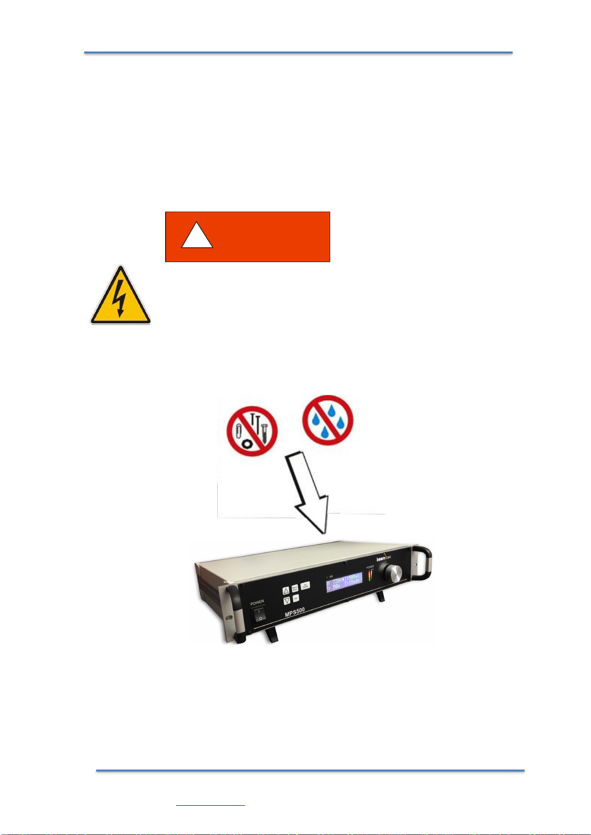
1.4.3. GENERAL SAFETY INSTRUCTIONS
For all work you are going to do, adhere to the applicable safety regulations. Also
observe all safety notes given in this document and forward the information to all other users
of the product. In particular, pay attention to the following safety notes:
Fig 1.0.1 Do not insert objects through louvers and keep device dry
Mains voltage.
Contact with live parts is extremely hazardous when any objects are
introduced or any liquids penetrate into the device.
Make sure that no objects enter through the louvers of the device. Keep the
device dry.
DANGER
!

MPS 500 –User Manual Rev. 2.1
BeamTec GmbH
Wolfgang-Paul-Str. 4, 89081 Ulm, Germany
http: www.beamtec.de , e-mail: info@beamtec.de tel.: +49 731 146620-0
8
Improper use.
Improper use can damage the MPS500.
Use the MPS500 only as intended by the manufacturer.
Improper installation and operation data.
Improper installation and operation data may damage the MPS500.
Strictly adhere to the stipulated installation and operation data.
WARNING
!
WARNING
!
MPS 500 User Manual Rev.2.1
BeamTec GmbH
Wolfgang-Paul-Str. 4, 89081 Ulm, Germany
http: www.beamtec.de , e-mail: info@beamtec.de tel.: +49 731 146620-0
9
2. TECHNICAL DATA
2.1. GENERAL DATA
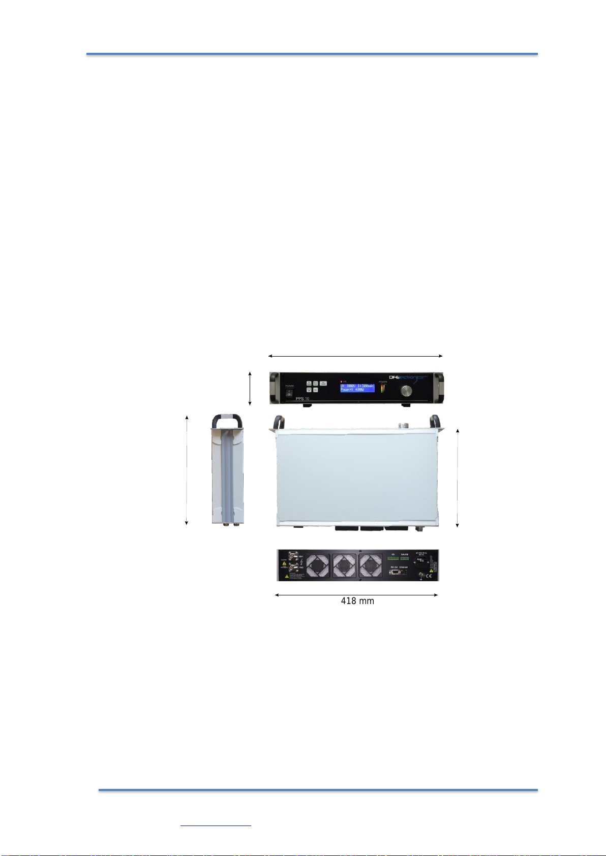
2.1.1. MECHANICAL DATA
Dimensions: Width: 482 mm
Height: 88,1 mm (2 HU)
Depth: 340 mm
See Fig . 2.1.1
Net Weight: 3,3 kg
Installation: 19” Rack standard or Bench Top unit
Fig. 2.1.1 Dimensions (mm)
Note: The image above is illustrative, rear panel connectors may differ depending on
the version of the device.
483 mm
87 mm
418 mm
310 mm
270 mm

MPS 500 –User Manual Rev. 2.1
BeamTec GmbH
Wolfgang-Paul-Str. 4, 89081 Ulm, Germany
http: www.beamtec.de , e-mail: info@beamtec.de tel.: +49 731 146620-0
10
2.1.2. AMBIENCE
Temperature Storage: -10…+60 °C
Operation Temperature: +5…+40 °C
Relative Humidity: Max. 80 % (up to 31 °C), decreasing to max. 50
% (above 40 °C)
Use indoor only
Altitude: max. 2000 m n.p.m.
The degree of dust standard: II
Humidity resistance: IP20
2.1.3. USE AND OPERATING MODES
There are three common operation modes:
- manual control, with 5 buttons user interface on the front panel
- software remote control, with RS232/RS485 or Ethernet Interface
( All Read commands are accessible all the time, Write commands are
accessible only with activation of this function from the user menu –see
remote control for use )
- hardware remote control with I/O interface –see Fig.3.3.1
This mode is active with external signal only. In this mode all of the front
buttons are deactivated.

MPS 500 User Manual Rev.2.1
BeamTec GmbH
Wolfgang-Paul-Str. 4, 89081 Ulm, Germany
http: www.beamtec.de , e-mail: info@beamtec.de tel.: +49 731 146620-0
11
2.1.4. STANDARDS
Conformity with the Directive relating to electrical equipment designed for use within
certain voltage limits 73/23/EWG
Conformity with the Directive relating to electromagnetic compatibility 89/336/EWG
Harmonized and international/national standards and specifications:
EN 61010-1 (Safety requirements for electrical equipment for measurement, control
and laboratory use)
EN 61000-6-2 (Electromagnetic compatibility generic immunity standard)
EN 61000-6-3 (Electromagnetic compatibility generic emission standard)
2.2. MAINS CONNECTION
Voltage: 230V for European, African, and Asian market
110V for American market
Frequency: 50 - 60 Hz
Current consumption: Max. 3,15A at 230V, 6,3A at 110V
Power consumption: Max. 600 W
Overvoltage category II
Protection class 1
Connection European appliance connector IEC 320 C14
Fuse T3,15A at 230V
T6A at 110V
2.3. SPECIFICATIONS
Input Supply Voltage
( Configurable with order )
90 to 132 VAC (50 to 60 Hz), 1 phase or
180 to 265 VAC (50 to 60 Hz), 1 phase
Current consumption
5 A max at 120 VAC and power 500 W
2,7 A max at 230 VAC and power 500 W
Output power
500W max
Output Voltage / Current
0–1000 VDC negative polarisation (1 volt resolution)
0–1000 mA (1 mA resolution)

MPS 500 –User Manual Rev. 2.1
BeamTec GmbH
Wolfgang-Paul-Str. 4, 89081 Ulm, Germany
http: www.beamtec.de , e-mail: info@beamtec.de tel.: +49 731 146620-0
12
Regulation mode
Power, Voltage or Current mode
Ripple Noise
Switching: 2% p-p (50 kHz)
Ramp Up time
0.1 …. 65 s
Communication Interface
RS232 and LAN/Ethernet 100Mb, Bluetooth in
standard
Type of control
Local or remotely
Arc Detection
Response time < 95 ns
Dimensions
418 mm x 270mm x 87 mm ( 2U high unit - 19”
standard )
Weight
6.1 kg
2.4 FEATURES:
Operating mode: DC
Two high-voltage outputs - the ability to support two independent magnetrons
without having to use an external switch
Fast response arc detection/suppression
Switched control methods (I, V, P) for maximum performance,
The ability to connect one active vacuum measuring head (optional)
Transparent interface with OLED display and desk light identification parameters
Built-in timer
Stable power operation from just 2W
High acceptance output impedance - ability to work with magnetrons of different
sizes
Suitable for working with one or two magnetrons
User-friendly interface with OLED display, keypad and rotary encoder

MPS 500 User Manual Rev.2.1
BeamTec GmbH
Wolfgang-Paul-Str. 4, 89081 Ulm, Germany
http: www.beamtec.de , e-mail: info@beamtec.de tel.: +49 731 146620-0
13
2.5. INTERFACES
2.5.1. I/O INTERFACE
Connector: D-Sub 25 female connector
Refer to chapter 3.3.5 for details
No of Digital Inputs: 6 –opto-isolated; 24VDC
No of Digital Outputs: 6 –OC type, opto-isolated; 24 VDC
No of Analog Inputs: 3 –voltage input type, opto-isolated ( 0..10V)
No of Analog Outputs: 3 –voltage output type, opto-isolated (0..10V)
Response time: 100 ms max
2.5.2. UART I(RS232/RS485 )
Connector: D-Sub 9; female connector
Transmission mode: 2400, 4800, 9600, 19200, 38400, 57600, 115200 bits/s
Data Length: 8 bit
Parity Control: none
Stop Bit: 1
Transmission Control: none
2.5.3 UART II BLUETOOTH
Transmission mode: 2400, 4800, 9600, 19200, 38400, 57600, 115200 bits/s
Data Length: 8 bit
Parity Control: none
Stop Bit: 1
Transmission Control: none
2.5.4 ETHERNET/IP
Connector: RJ45
Transmission mode: 100 MB/s
TCP/IP stack, IPv4
NOTE: The communication protocol is decribed in separate document

MPS 500 –User Manual Rev. 2.1
BeamTec GmbH
Wolfgang-Paul-Str. 4, 89081 Ulm, Germany
http: www.beamtec.de , e-mail: info@beamtec.de tel.: +49 731 146620-0
14
3. INSTALLATION
3.1. UNPACKING
1. Visually inspect the transport packaging for signs of external damage
2. Unpack the MPS500 and put the packaging material aside
Note: Keep the packaging material for later use. The MPS500 must be stored
and transported in the original packaging material only.
3. Examine the MPS500 for completeness
4. Visually inspect the MPS500 for signs of damage
Damaged product.
Putting a damaged product into operation can be extremely dangerous.
Never attempt to put a damaged product into operation. Secure the damaged
product from unintended operation. Send a damage report to the haulage
company or the insurer.
3.2. MECHANICAL INSTALLATION
MPS500 can be used in the following ways: as a bench top device, mounted in
a control panel or mounted in a 19 "rack. In each case, consider the following
important safety information:
The temperature of the environment.
Exceeding the allowable temperature of the device may damage the unit.
DANGER
!
WARNING
!
MPS 500 User Manual Rev.2.1
BeamTec GmbH
Wolfgang-Paul-Str. 4, 89081 Ulm, Germany
http: www.beamtec.de , e-mail: info@beamtec.de tel.: +49 731 146620-0
15
Make sure that the maximum permissible ambient temperature is not
exceeded, and the air can circulate freely through the ventilation slots. Do
not expose the device to direct sunlight.
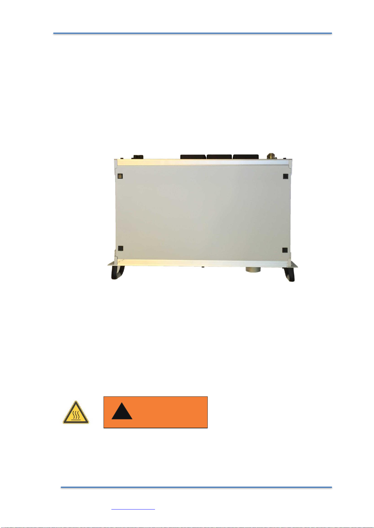
3.2.1. BENCH TOP UNIT
MPS500 is supplied with a 4 prop-up feet, which, when the device is to be used as a
stand-alone device, must be installed as shown in Fig. 3.2.0
Fig 3.2.0
NOTE: The prop-up feet must be fixed only with the screws supplied. In
the case of rack mounting, prop-up feet should not be installed
3.2.2. RACK INSTALLATION
The MPS500 is designed for installation into a rack according to DIN 41 494 (19", 3
HU).
WARNING
!

MPS 500 –User Manual Rev. 2.1
BeamTec GmbH
Wolfgang-Paul-Str. 4, 89081 Ulm, Germany
http: www.beamtec.de , e-mail: info@beamtec.de tel.: +49 731 146620-0
16
Ambient temperature.
Exceeding the maximum permitted ambient temperature may damage the device.
Make sure that the maximum permitted ambient temperature is not exceeded and
that the air can flow freely through the louvers. Do not expose the device to direct
sunlight.
Protection class of the rack.
If the product is installed in a rack, it is likely to lower the protection class of the
rack (protection from foreign bodies and water) e.g. according to the EN 60204-1
regulations for switching cabinets.
Take appropriate measures to restore the required protection class of the rack.
In case of rack installation, all of the prop-up feet have to be removed. To do this:
1. Turn the MPS500 off and remove the mains cable.
2. Carefully turn the MPS500 over to reveal the bottom as shown in Fig. 3.2.0.
3. Unscrew and remove the prop-up feet
4. Turn the MPS500 to the normal position and install in the rack
Note: To reduce the stress on the front panel, the device must be supported with rack
rails.
1. Insert MPS500 guides.
2. Screw the MPS500 using the supplied screws and plastic sleeves.
DANGER
!
MPS 500 User Manual Rev.2.1
BeamTec GmbH
Wolfgang-Paul-Str. 4, 89081 Ulm, Germany
http: www.beamtec.de , e-mail: info@beamtec.de tel.: +49 731 146620-0
17
3.3. CONNECTING
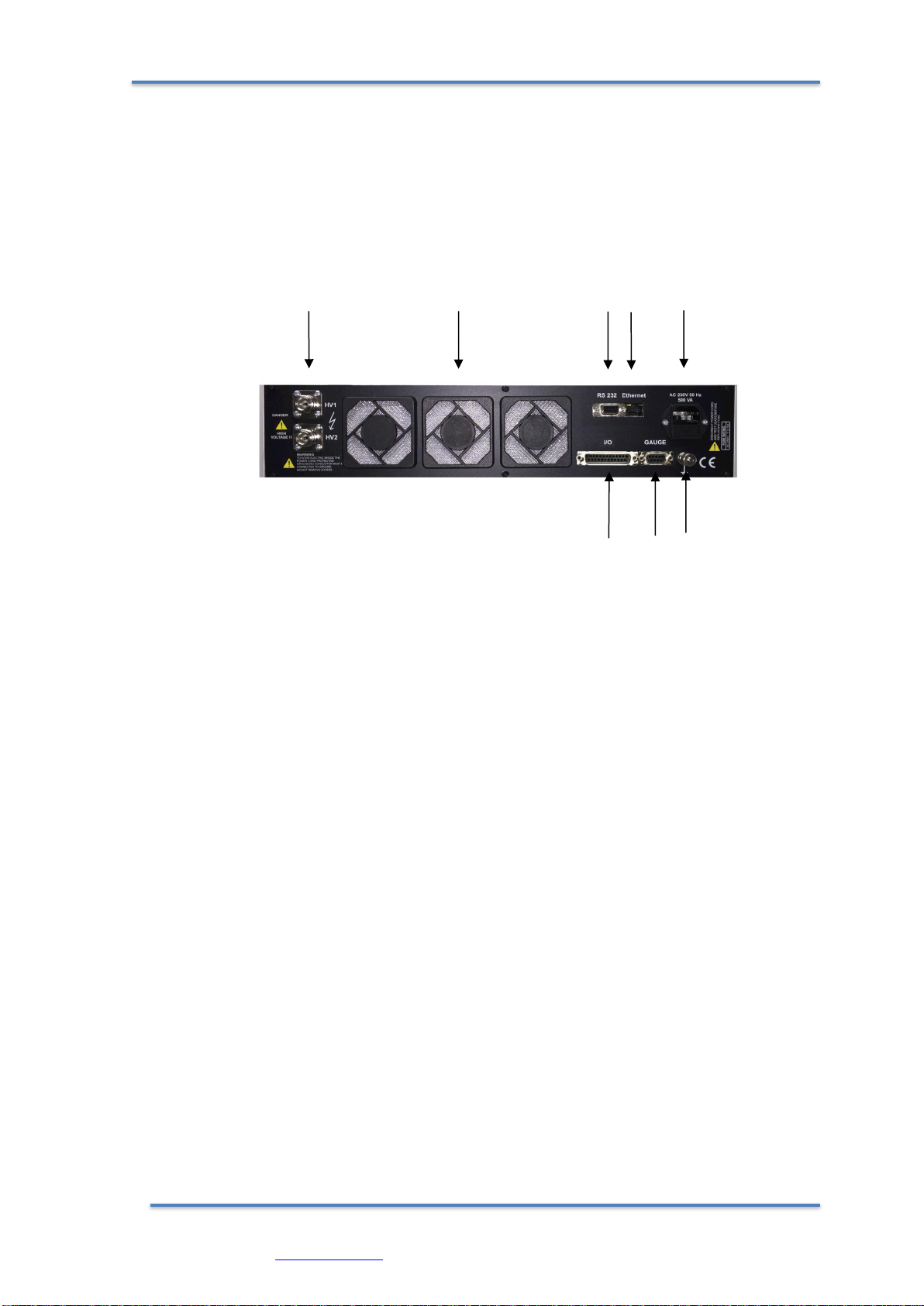
3.3.1. REAR PANEL
AB C D E
F G H
Fig. 3.3.0 Rear panel MPS500
A –HV1 and HV2 output connectors type N-50/2-0/G1.07
B –fans and filters
C - RS232 interface Dsub 9 female ( RS485 optionally )
D –Ethernet interface RJ45
E –main power socket IEC C13
F –I/O interface connector Dsub 25 female ( see chapter 3.3.5 for details )
G –Vacuum Gauge Connector ( Dsub 9 )
H –grounding pin

MPS 500 –User Manual Rev. 2.1
BeamTec GmbH
Wolfgang-Paul-Str. 4, 89081 Ulm, Germany
http: www.beamtec.de , e-mail: info@beamtec.de tel.: +49 731 146620-0
18
Screw for internal protective conductor.
The internal protective conductor is connected to the casing with a screw.
Do not turn or loosen this screw.
The configuration of the available connections and photographs of cables is described
in the following sections.
3.3.2. MAINS CONNECTION
The mains connection is designed for a mains cable which contains IEC 320 connector
on the device side. A mains cable is supplied with the device. If the plug is not
compatible with your wall socket, you should replace it with a suitable mains cable:
Three-conductor cable with protective ground
Conductor cross-section 3x1.5 mm2or larger
Fig. 3.3.1 Three-conductor cable with protective ground (example)
DANGER
!

MPS 500 User Manual Rev.2.1
BeamTec GmbH
Wolfgang-Paul-Str. 4, 89081 Ulm, Germany
http: www.beamtec.de , e-mail: info@beamtec.de tel.: +49 731 146620-0
19
Mains power.
Improperly grounded devices can be extremely dangerous in the event of a
fault. Use three-wire mains or extension cables with protective ground only.
Plug the mains cable into wall sockets with protective ground only.
1. Connect the European appliance connector of the mains cord with the mains
connection of the device
2. Connect the plug of the mains cable with the wall socket
Note:
If the device is installed in a switching cabinet, the mains power can be supplied via a
switchable central power distributor.
3.3.3. GROUNDING
Grounding screw (Fig. 3.3.0, the reference H) should be used to connect the MPS500
with the main grounding system in which it operates. It is recommended to use a
cable with a minimum section of 2.5 mm2
If required, connect the vacuum system ground from the earthing screw using the
protective conductor.
3.3.4. HIGH VOLTAGE CONNECTORS HV1 AND HV2
The power supply is equipped with two HV outputs of N-50/2-0/G1.07 type. Output
configuration is set by the software user interface. Please refer to chapter 4.3.0
1
DANGER
!

MPS 500 –User Manual Rev. 2.1
BeamTec GmbH
Wolfgang-Paul-Str. 4, 89081 Ulm, Germany
http: www.beamtec.de , e-mail: info@beamtec.de tel.: +49 731 146620-0
20
2
Fig. 3.3.0 HV connector , N-50/2-0/G1.07 type
1 –HV1 ( - 1000 VDC )
2 –HV2 ( - 1000 VDC )
It is recommended not to run the device without a connected load. Doing
so can damage the power supply
CAUTION
!
Hazardous voltage.
After entering "Operate" mode (HV LED indicator on the front panel is lit),
the connector develops voltage levels dangerous to life and health. The
device must be turned off and completely isolated before any work
associated with connecting or disconnecting the high voltage cable. When
turned off, you must wait at least 15 seconds before attempting to connect /
disconnect the HV cable.
DANGER
!
Table of contents


