Beat-Sonic encore a PA2T1K User manual
■ Features
NO:000001
PA2T1K Instruction Manual
- Designed for Toyota 10-pin / 6-pin radio connectors
- Class AB high efficiency car audio amplifier
- Easy to install plug & play installation
- Retains factory head unit, speakers and connectors
- Manufactured using premium hi-fi audio grade components
- Made in Japan
■ Important
Thank you for purchasing the Beat-Sonic PA2T1K Plug & Play Power Amplifier. Designed
and made in Japan, this product represents our commitment to quality and excellence.
Please read this manual carefully prior to installing this product to ensure correct operation.
- This product is installed using the factory harness connectors, however there are multiple
factory harness connectors of the same size and shape. Do not plug into the wrong connector
or serious damage may result. Contact Beat-Sonic if unsure.
- Check the Beat-Sonic website for the latest vehicle compatibility information before installing.
- Some vehicles may require extensive disassembly to install this product. Installation should be
performed by an experienced motor vehicle technician or auto electrical professional.
■ Protection Circuit
■ Contents
■ Precautions
- This amplifier is suitable for negative ground 12V DC operation only.
- Wrap cables in protective electrical tape when routing near metal brackets and sharp edges.
- Do not install main unit or harness near moving mechanisms such as the steering column,
seat rails, pedals etc.
- Do not install this product where it may get wet or in areas where it is likely to get dusty or dirty.
- Do not open, disassemble or modify this product.
- Ensure the car battery is in good condition. A weak battery will cause a significant drop in
power output and sound quality.
This amplifier is provided with a protection circuit that operates in the following conditions:
- When the speaker output terminals are short circuited
- When the battery is connected in reverse polarity
- When the amplifier is overheated
If this occurs, turn off the ignition and determine the cause of the malfunction. In case of
overheating, wait until the amplifier has cooled off before using.
45W x 4ch (4Ω)
Power output
Speaker impedance
Input sensitivity
Bandwidth
Total harmonic distortion
Operating voltage
Quiescent current
Fuse
Audio input
Protection
4 ~ 8Ω
0.5 ~ 5V
15 ~ 80kHz (+0, -1dB)
0.01%(1kHz / 4 Ω )
DC11V ~ 15V
200mA
15A
AUX (Line Level RCA)
Speaker High Level
Class AB amplifier 4 channels
Dimensions
Weight 420g (exc. harness)
Short circuit / reverse polarity / heat protection
96mm (W) x 114mm (D) x 40mm (H)
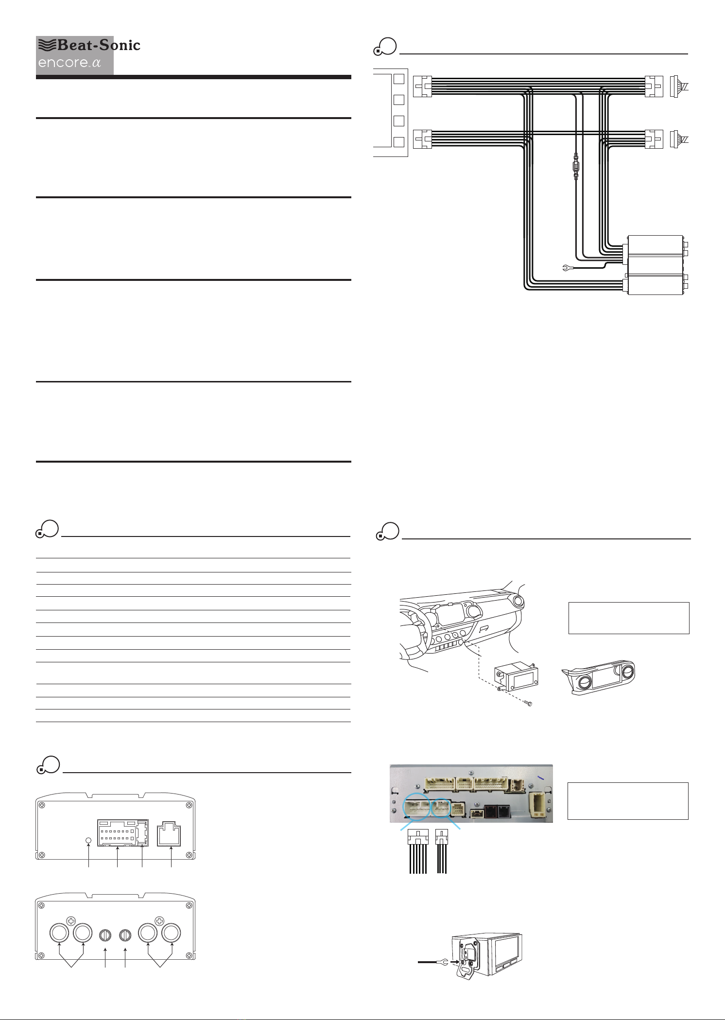
Parts Location
⑤ ⑦ ⑧⑥
FRONTREAR
GAIN
F
R
④③②
High Level
Input
⑤
Rear Channel RCA Input
⑥
Rear Channel Gain
⑦
Front Channel Gain
⑧
Front Channel RCA Input
①
Power Indicator
②
Power / Speaker Output Connector
③
Fuse (15A)
④
High Level Input Connector
①
1Specifications
2
Connection Diagram
3
Factory
head unit
6-pin
connector
10-pin
connector
Factory
6-pin
connector
Factory
10-pin
connector
8-pin
connector
(white)
16-pin
connector
(grey)
PA2 Amplifier
Chassis Ground
Installation
4
4.1 Remove all necessary parts to gain access to the rear of the factory head unit. The
method of disassembly varies for each vehicle. If unsure, please contact Beat-Sonic
for advice for vehicle specific instructions.
4.2 Locate the 10-pin connector and the 6-pin connector on the back of the factory
head unit. Disconnect the 10-pin connector and 6-pin connector from the back of
the factory head unit and connect the PA2T1K connectors inline with the factory
connectors in a daisy chain configuration (see section 3).
10-pin
connector
6-pin
connector
4.3 Attach the chassis ground terminal to the mounting bracket for the factory head unit.
Loosen one of the fasteners using the correct size socket or spanner then slide the
chassis ground terminal underneath before retightening the fastener.
Chassis Ground
Factory
head unit
PA2 Main Unit x 1
Instruction Manual x 1
Wiring Harness x 1
Padding Strips x 2
Double Sided Tape x 2
Carpet Mounting Tape x 2
Diagram for illustration purposes.
Actual radio and panels will
vary
according to model and grade.
Photos are for illustration purposes.
Actual radio, number of connectors
and connector positions will
vary
according to model and grade.
Installation (continued)
4
Gain Adjustment
5
4.4 Decide a suitable location to mount the PA2 amplifier. The mounting location will
vary depending on the vehicle. Suggested mounting locations include behind the
factory head unit, inside the glove compartment, behind the glove compartment or
under the passenger seat.
i) If installing behind the factory head unit, behind the glove compartment or other
location inside the dash, use the use the supplied foam padding strips by cutting
to size to insulate against possible rattles from metal to metal contact.
ii) If installing inside the glove compartment, use the provided double sided tape
strips to secure the amplifier in place. An opening may need to be cut into the
top/side of the glove compartment to allow the cables to pass through. Before
installing, confirm the glove compartment can be freely opened and
closed with
the amplifier in place, and the cables do not obstruct moving parts.
iii) If installing under the passenger seat, first confirm the cable length will reach the
desired location under the seat. After confirming, attach the supplied carpet
mounting tape to the underside of the PA2 amplifier. The carpet mounting tape
will grip the carpet and hold the amplifier in place.
4.5 Route the PA2 wiring harness to the location of the amplifier and connect both the
16-pin grey connector and 8-pin white connector to the amplifier.
4.6 Confirm all connectors are fully inserted before reinstalling the head unit back into
it’s original position. Test the system by turning on the radio and confim that sound
is output from all speakers. Play music through the sound system and adjust the
gain if necessary (see section 5 below).
4.7 Return panels and trim to the original locations taking care to ensure all connectors
are reconnected to complete the installation.
Gain adjustment allows optimization of the factory head unit volume range in relation to the
amount of power output by the PA2 amplifier. In most installations, the gain on the PA2
amplifier can be left at the factory preset maximum gain (approx. 5 o’clock) position. In
some cases however, adjustment may be necessary to prevent overdriving the speakers at
relatively low volumes.
5.1 Adjust factory head unit bass, treble, balance and any other equalizer settings to the
mid point positions.
5.2 Play music with impactful bass, treble and vocals. Slowly increase the volume on the
factory radio to a medium-high level while carefully listening for any distortion.
Use your
finger
nail or small flat head screwdriver to adjust the gain on the front and rear channels
for maximum volume without distortion or overdriving the speakers.
FRONTREAR
GAIN
FR
Turn clockwise
to increase gain
Do not apply excessive
force to gain control.
Maximum gain is at 5
& minimum gain is at 7.
Turn anti-clockwise
to decrease gain
472-5 Koushin, Fujieda, Nisshin, Aichi, 470-0112, JAPAN
TEL: +81-561-75-1655 FAX: +81-561-74-5595
International
USA and Canada
14778 Beach Blvd. La Mirada, CA 90638
TEL: 1-714-994-1085 FAX: 1-714-249-4741
Beat-Sonic USA Inc.
12
39
57
8
1
2
4
10
11
6
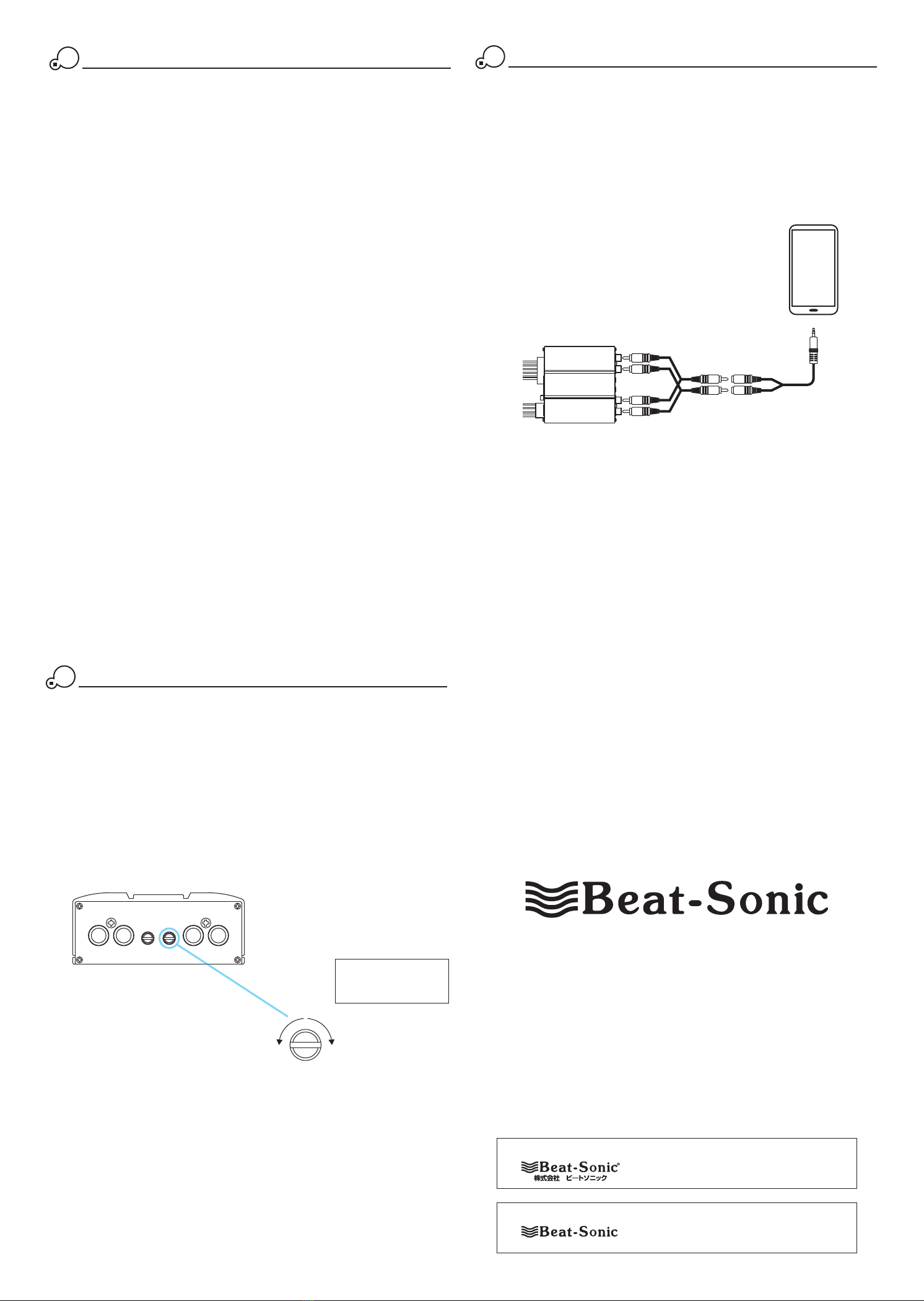
RCA
RCA
RCA splitter cable x 2
Optional Connection - RCA Inputs
PA2 Amplifier
3.5mm to RCA cable
The PA2 is provided with 4 channel line level (RCA) inputs. These inputs can be used
to connect an additional audio source device that can be played either simultaneously
or separately to the high level inputs from the factory head unit.
As an example, the headphone output (3.5mm) from a smartphone can be connected
to the RCA inputs on the PA2 amplifier by using a 3.5mm to RCA cable together with
2 x RCA splitter cables.
*3.5mm to RCA cable and RCA splitter cables are sold separately and are not included.
Appendix A
6
Other Beat-Sonic Automobile Accessories manuals

Beat-Sonic
Beat-Sonic MVA-81 User manual

Beat-Sonic
Beat-Sonic NDS6223EP User manual

Beat-Sonic
Beat-Sonic SLX-140L User manual

Beat-Sonic
Beat-Sonic Altezza & Gita SLA-91 User manual

Beat-Sonic
Beat-Sonic CS6EP User manual

Beat-Sonic
Beat-Sonic Altezza & Gita SLA-91 User manual

Beat-Sonic
Beat-Sonic SLA-91 User manual
Popular Automobile Accessories manuals by other brands

Rear view safety
Rear view safety RVS-7706133 product manual

Havis-Shields
Havis-Shields KK-K9-C14-K-32 installation instructions

Brodit
Brodit ProClip 854344 installation instructions

Atera
Atera Signo 045 012 User information

TentBox
TentBox Cargo installation manual

Ridetech
Ridetech 11059121 installation instructions


