Beat-Sonic MVA-81 User manual

- Interface Adapter Module and Harness x 1
- 1-DIN Side Panels (Left & Right) x 1 pair
NO:000001
- Allows installation of a single-DIN (178mm x 50mm) head unit to replace factory head unit.
-
Retains full function of factory EMV touch screen navigation and climate control systems.
- Compatible with 9 speaker sound system with factory amplifier and DVD-ROM navigation.
- Plug and play adapter with no modifications required to factory vehicle electrical harness.
- Perform installation with patience and due care to prevent damage to this product or any part of the vehicle.
- Ensure all connectors, cables and terminals are correctly secured and fully inserted. Loose and/or improperly secured
connectors will cause malfunction.
- Always grasp the connector plug when disconnecting the cable harness. Never disconnect connectors by pulling on the
harness wires as serious damage can occur.
- Do not attempt to install this product on any other vehicle other than the specified models.
- Do not disassemble, modify or attempt to repair this device. Doing so will render the warranty void.
- Beat-Sonic and its affiliates shall not be held responsible for any consequence, either directly or otherwise, as a result of
installing and/or using this product.
- Disconnect negative terminal of the vehicle battery prior to installation to prevent risk of short circuit.
Ŷ)HDWXUHV
Ŷ,PSRUWDQW
Ŷ&RQWHQWV
Ŷ3UHFDXWLRQV
/DQG&UXLVHU3UDGR
/H[XV*; MVA-81
,QVWDOODWLRQ0DQXDO
- Instruction Manual x 1
Thank you for purchasing the Beat-Sonic MVA-81 Audio Interface Adapter Kit. You have purchased
from Japan`s leading supplier of car audio interface adapters and accessories.
Designed and made in Japan, this product represents our commitment to quality and excellence.
Please read this manual carefully prior to installing this product to ensure correct operation.
TV L
TV R
- Factory CD / DVD changer located inside the glove compartment will no longer function after removing the factory head
unit. Regardless, do not remove CD / DVD changer as removal will result in system malfunction.
- Front / rear fader and any DSP functions on the aftermarket head unit will have no effect with this installation.
- Factory AUX input and Radio Data Service (RDS) will no longer function after removing the OEM head unit.
- Aftermarket head unit must support steering wheel audio buttons to retain this functionality. Depending on the aftermarket
head unit, a separate steering wheel button interface may be required. See Appendix A on next page.
- This product is not compatible with connector type (20-pin) steering wheel control adapters. Please use wired type only.
- This product will not rectify any pre-existing faults with the electrical system, factory amplifier and/or speakers.
- This product should be installed by an experienced motor vehicle technician or automotive electrical professional.
- The user assumes all responsibility for any damages and/or injuries caused as a result of improper installation.
&RQQHFWLRQ'LDJUDP
5HPRYHWKH(09$XGLR$VVHPEO\
Disconnect the negative terminal of the vehicle battery and wait at least 90 seconds before
proceeding to prevent accidental airbag deployment.
1.1 Remove the Side Garnish panels on either side of the centre console by pulling away
to disengage the clips.
1.2 Remove the Air Vents on either side of the EMV Audio Assembly by pulling away to
disengage the clips.
1.3 Remove the Ash Tray by pulling away to disengage the clips.
1.4 Unscrew the 4 fasteners that secure the EMV Audio Assembly the disconnect the
connectors behind to remove.
,QVWDOODWLRQ
No connection. TV Audio Input only available for
Japanese domestic vehicles with factory TV tuner
Aftermarket Head Unit
No connection required
for rear speaker outputs
FRONT
Ground
Ground
(SWG)
(ORANGE) Illumination
(BLUE) Antenna Remote
(YELLOW) +12V Battery
(RED) Accessories
Vehicle Side
20-Pin
Connector
(Large)
Vehicle Side
20-Pin
Connector
(Small)
20-Pin
Connector
(Small)
20-Pin
Connector
(Large)
Vehicle Side
12-Pin
Connector
12-Pin
Connector
09$
④EMV Audio Assembly
②Air Vent Right
③Ash Tray
①Side Garnish
②Air Vent Left
①Side Garnish
Fastener x 2
,QVWDOOWKH6LQJOH',1+HDG8QLW
2.1 Remove the mounting brackets from
the EMV Audio Assembly then
remove the factory radio unit.
2.2 Attach the aftermarket Single DIN
Head Unit to the brackets using the
fasteners that came supplied with
the aftermarket head unit.
Side Bracket
2.4 Re-attach the side brackets to the EMV Audio Assembly taking care to align the locating
points on both sides and insert the newly installed aftermarket head unit into the
opening.
2.5 Connect the MVA-81 adapter harness and all EMV Audio Assembly connectors.
Refer to Appendix A overleaf for connection of steering wheel audio controls.
2.6 Re-assemble all parts in reverse order to complete the installation.
See Appendix A for
SW1, SW2 & SWG
steering wheel audio
button controls
2.3 Attach the side panels using the pre-applied high
strength double sided tape.
Fastener x 2
Side Bracket
Side Panel
Side Panel
Locating Points
Fastener x 2
Do not remove or disconnect
factory CD / DVD changer
inside the glove compartment
,03257$17
OEM NavCompatible Vehicles
Toyota Land Cruiser Prado
with 9 Speaker Sound
Lexus GX470
Year Chassis Code
2002 - 2009 J120
DVD-ROM
Navigation

Steering Wheel Audio Button Connection (Optional)
Vehicles equipped with factory steering wheel audio buttons can retain this function by hard
wiring a suitable steering wheel interface adapter (sold separately) to the smaller 20-Pin
Connector. It is important to observe the following:
SWG
SW1
SW2
20-Pin Connector
(Small)
Steering Wheel
Adapter
(Sold Separately)
- Use hard wired steering wheel adapters only.
- Use wire taps to connect steering wheel adapter SW1 and SW2 wires.
- 20-Pin Connector (Small) of MVA-81 must remain connected together with steering wheel adapter.
- Aftermarket head unit must support steering wheel button connection to enable this feature.
10
9
7
6
5
2
3
8
1
20
19
17
16
15
18
13
12
11
Viewed from back of connector
with wires exiting toward viewer
Pin 6: SWG
Pin 7: SW1
Pin 8: SW2
4
14
Appendix A
Installation Tip
(Please take your time to read this before performing installation)
1. Before removing OEM head unit, confirm that the fader, balance, bass and treble levels are at
the center/neutral or “0”on the OEM head unit. If this is not performed correctly, you may have
problem with the volume or the fader during or after the installation.
2. Before removing OEM head unit, set the volume on the OEM head unit at 50%. If this is not
performed correctly, you may experience weak sound, no sound or distortion after the
installation.
3. The factory amplifier memorizes the fader, balance and volume set up. Please set up according
to above recommendations before removing the OEM head unit.
Trouble Shooting –No Sound
Step 1 :Follow the above recommendations.
Step2: Please make sure ALL OEM connectors and Beat-Sonic connectors are securely connected. If
something’s not connected, something will not work.
Step3 : Please make sure the speaker wires on the Beat-Sonic sound module are connected to the
aftermarket high-level speakers wires accordingly to the instruction. (Please do not use the RCA cables)
If there are only Front L & R speaker wires on the Beat-Sonic sound module, please make sure that it’s
only connected to Front Left & Front Right only. Most Lexus models are equipped with the 2 channel
amplifier, and you can only connect two speaker wires. Beat-Sonic sound module will distribute sounds
evenly throughout all speakers just by connecting front left and front right speaker wires as suggested.
Step4 : Test factory amplifier and speakers by using the OEM head unit. If there’s no sound with the
OEM head unit, either the amplifier or the speakers are malfunctioning.
Step5 : Check fader on the OEM head unit, and make sure it’s at the center/neutral or “0”.
Step6 : Check the fuse.
It is very easy to miss and not connect one or more connectors during installation. Please take your time
and check if all connectors are securely connected, before reinstalling all your dash panels.
Other Beat-Sonic Automobile Accessories manuals

Beat-Sonic
Beat-Sonic SLA-91 User manual
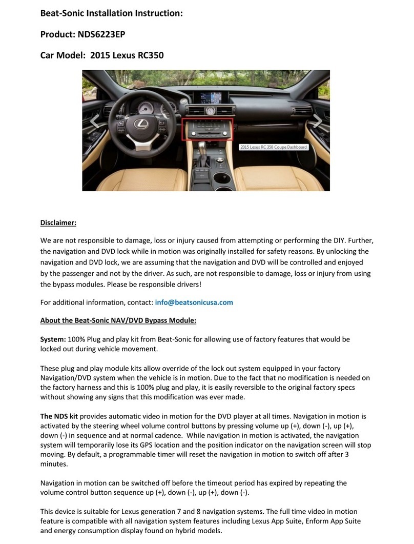
Beat-Sonic
Beat-Sonic NDS6223EP User manual
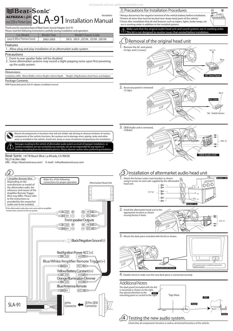
Beat-Sonic
Beat-Sonic Altezza & Gita SLA-91 User manual
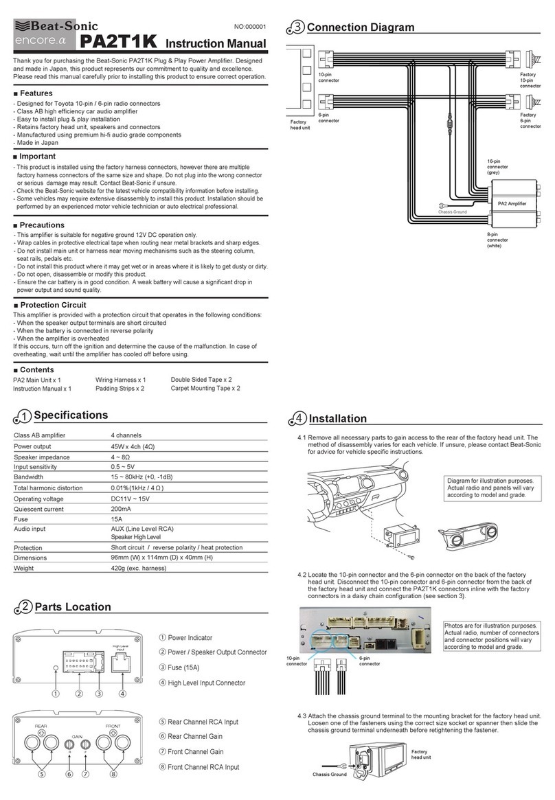
Beat-Sonic
Beat-Sonic encore a PA2T1K User manual

Beat-Sonic
Beat-Sonic Altezza & Gita SLA-91 User manual
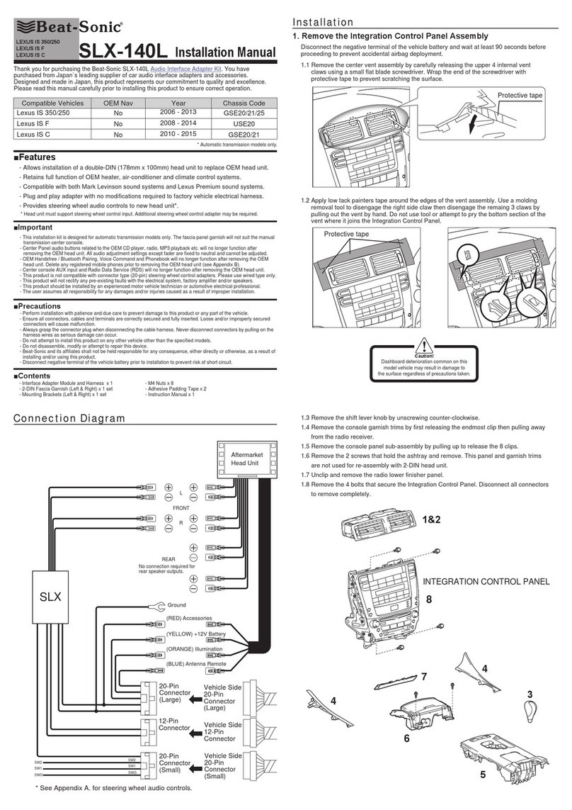
Beat-Sonic
Beat-Sonic SLX-140L User manual
Beat-Sonic
Beat-Sonic CS6EP User manual
Popular Automobile Accessories manuals by other brands

ULTIMATE SPEED
ULTIMATE SPEED 279746 Assembly and Safety Advice

SSV Works
SSV Works DF-F65 manual

ULTIMATE SPEED
ULTIMATE SPEED CARBON Assembly and Safety Advice

Witter
Witter F174 Fitting instructions

WeatherTech
WeatherTech No-Drill installation instructions

TAUBENREUTHER
TAUBENREUTHER 1-336050 Installation instruction


