Becen BC-M230B User manual

www.szbecen.com
USER’S MANUAL
Model: BC-M230B
230w Beam Moving Head Light (Black)
Package Includes:
1 x beam moving head light
1 x clamp,handle
1 x safe cable
1 x power cable
1 x DMX cable
Please read this manual before use

www.szbecen.com
CONTENTS
Chapter 1 Warnings and Operation Modes.................................................................................... 1
1.1 Warnings.......................................................................................................................... 1
1.2 Operation Modes........................................................................................................... 1
Chapter 2 Control Panel Instructions............................................................................................. 2
2.1 Main Interface.................................................................................................................. 2
2.2 Setting of Interface .......................................................................................................... 3
2.3 Information Interface....................................................................................................... 3
2.4 Information Interface....................................................................................................... 4
2.5 Advanced Interface.......................................................................................................... 4
Chapter 3 Channel description....................................................................................................... 5
3.1 Channel table................................................................................................................... 5
3.2 Channel Detail................................................................................................................. 5
3.2.1 COLOR WHEEL-channel 1.................................................................................... 5
3.2.2 STOP/STOBE-channel 2 ......................................................................................... 7
3.2.3 DIMMER-channel 3................................................................................................ 7
3.2.4 STATIC GOBO CHANGE-channel 4...................................................................... 7
3.2.5 PRISM INSERTION-channel 5............................................................................... 9
3.2.6 PRISM ROTATION-channel 6................................................................................ 9
3.2.7 PRISM ROTATION-channel 6................................................................................ 9
3.2.8 PRISM ROTATION-channel 6................................................................................ 9
3.2.9 FOCUS-channel 9.................................................................................................... 9
3.2.10 PAN-channel 10..................................................................................................... 9
3.2.11 PAN FINE-channel 11 ........................................................................................... 9
3.2.12 TILI-channel 12................................................................................................... 10
3.2.13 TILT FINE-channel 13......................................................................................... 10
3.2.14 FUNCTION-channel 14(NOUSED).................................................................... 10
3.2.15 RESET-channel 15............................................................................................... 10
3.2.16 LAMP CONTROL-channel 16............................................................................ 10
3.2.17 TIMING CHANNELS......................................................................................... 10
Chapter 4 Control signal connection ........................................................................................... 10
Chapter 5 Installation................................................................................................................... 12
Chapter 6 Protection and Maintenance........................................................................................ 18
6.1 Light cleaning................................................................................................................ 18
6.2 Statement ....................................................................................................................... 19
6.3 Problem solve method ................................................................................................... 19

1
www.szbecen.com
Chapter 1 Warnings and Operation Modes
1.1 Warnings:
Please check if there is any transportation damage before using. And if there is any
damage, please stop using it, and contact the distributor or manufacturer as soon as
possible. Please keep it away from Combustible materials, and unlock the X-, Y-axis
before using. The fixture should be installed in places with good ventilation, keep it
away from the wall at least 10cm above, and then check if the fans are in good
conditions.
Please don’t project the light beam on the combustible directly, and keep the fixture at
least 12m away from the projection objects.
Please don’t look directly into the light source lest any damage to your eyes. And
please make sure the using power voltage is in accordance with the stated voltages
before using.
Attention: Please power off before installing, repairing or cleaning
the fixture.
1.2 Operation Modes
For example, how to change DMX address?
Please press “Setting”in the main interface to enter “setting”interface.
There are 4 touch key-presses on the right side, namely, “Up”“Confirm”“Down”
“Return”buttons.
Please press “Up”or “Down”keys to enter “DMX address”.
Please press “Confirm”to edit.
Please press “Up”or “Down”keys to change DMX address(the new DMX
address would be saved automatically and start to run)
Please press “Confirm”to exit editing.
Please press “Return”to exit main manual.
Operation modes for turning wheel:
Please press “Setting”button under the main interface, and turn the wheel.
Touch
Turning Wheel
Function
“Up”button
Turn left
Select、Edit
“Down”button
Turn right
Select、Edit
“Confirm”button(“OK”)
Press the wheel
Start running
Start editing、Stop editing
“Return”button
Press the wheel under
Return manual
Return to previous page

2
www.szbecen.com
Please press the wheel to enter “setting”interface.
Please turn the wheel to enter “DMX address”interface under “setting”interface.
Please press the wheel to edit.
Please turn the wheel to change the DMX address.
Please press the wheel to exit editing after the modification.
Please turn the wheel to enter “Return”, and then press the wheel to return the
main interface.
Chapter 2 Control Panel Instructions
2.1. Main Interface
The 3 buttons on the up right corner are for language switch and screen rotation.
The 4 buttons on the bottom are for sub-interfaces.
How to use the wheel to control the sub-interface? Please see as follows::
For “Up”button: Please turn left.
For “Down”button: Please turn right.
For “Confirm”button: Please press the wheel.
Operation of Dialog by turning wheel:
If for “YES”, then press the wheel. And if for “No”, then turn the wheel.
3
www.szbecen.com
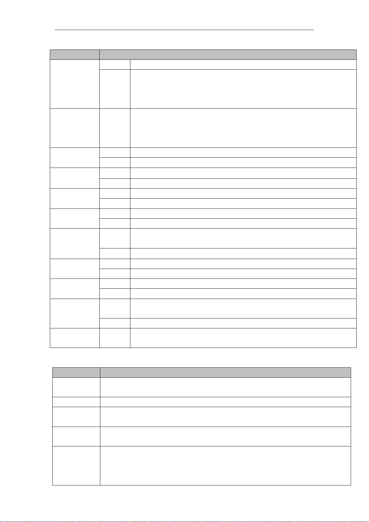
2.2. Setting of Interface
Options
Instructions
Running
Mode
DMX
Slave machines:accept DMX signals from controller or Master machine.
Auto
Master-Slave:running automatically, and send DMX signals to slave
machines.
Attention:If need to check the light effects, please power on the lamp
first to enter self-propelled state.
DMX
Address
1-512
Press “Confirm”button to edit. First is for “hundred's digit”, and press
“Up”and “Down”to change the address codes. Press “Confirm”button
the second time to edit “ten's digit”, and press again the “Confirm”
button to edit “unit's digit”.Please press it again to exit editing.
Channels
16
17-20 CH Invalid
20
17-20CH to control speed(please refer to Channel chart)
X Reverse
off
on
Y Reverse
off
on
XY Exchange
off
on
Exchanging XY channels(Pan/Tilt fine included)
XY Encorder
on
Use Encorder (optocoupler) to judge out of sync or not, and self-correct
the position.
off
Don’t use Encorder (optocoupler) to rectify the position
No DMX
signal
stay
Stay the same
reset
Stop running
Screen Save
mode
on
Screen light off automatically after 30secs
off
Screen stay on
Starting up
off
Reset directly when power on,lamp stay off(need to operate the manu or
console to light up the lamp)
on
Lamp on when power on,and reset after the lamp is fully lighted up.
Recover
default setting
Press “Confirm”button to see the confirm dialog, and press “Confirm”
button again to recover default setting.
2.3.Information Interface
Options
Illustrate
Software
version
The current software version
Total time
Total time (accurate to the minute)
The use of
time
Since the boot (accurate to the minute)
DMX
Channel
Click here to go to the sub-interface, numerical and percentage display channel
for viewing.
System error
records
If the red ERR indicator light, illustrate lamps run error, Details Click here go to
the sub-interface view. After you finish, press "OK" key to delete error records.
Note: sometimes it is not Hall or optocoupler installation problems, but the motor
line reversed.
Table of contents
Other Becen Lighting Equipment manuals

Becen
Becen BC-WR912 User manual

Becen
Becen BC-LE300 User manual

Becen
Becen BC-410D User manual

Becen
Becen BC-246Z User manual

Becen
Becen BC-W403 User manual

Becen
Becen BC-M200 User manual

Becen
Becen BC-P419 User manual

Becen
Becen BC-P100 User manual

Becen
Becen BC-410F User manual

Becen
Becen BC-410E User manual


