Beck 982R User manual
982R
Kompakte Luft-/Differenzdruck-Messumformer
mit einstellbarem Druckmessbereich für
-Gebäudeautomation, Klima- & Reinraumtechnik
-Ventil- & Klappensteuerung
-Filter-, Ventilatoren- & Gebläseüberwachung
-Kontrolle von Luftströmungen
Compact Air/Differential Pressure Transducer
with adjustable pressure range for
-Building automation, air-conditioning & clean room technology
-Valve & shutter control
-Filter, ventilator & fan monitoring
-Air-flow control

BESTELLMATRIX 982R. 6 X 3 X 0 6
ORDER MATRIX I II III IV V VI
I Schutzart IP54 Bestell-Code
Protection category IP54 Order code
mit Hutmutterverschraubung M12, 6
with cap nut conduit M12
II Auswählbare Druckmessbereiche
Selectable pressure ranges
0…100 Pa (0…1,0 mbar) 2
0…250 Pa (0…2,5 mbar) 3
0…500 Pa (0…5,0 mbar) 4
0…1000 Pa (0…10 mbar) 5
0…2,5 kPa (0…25 mbar) 6
0…5,0 kPa (0…50 mbar) 7
0…10,0 kPa (0…100 mbar) 8
0…25,0 kPa (0…250 mbar) 9
0…50,0 kPa (0…500 mbar) A
0…100 kPa (0…1,0 bar) B
0…250 kPa (0…2,5 bar)
F
III Druckeinheit
Pressure unit
Pascal
3
IV Ausgangssignal und Versorgung
Output signal and supply
0 …10 V, linear, 24 VAC/VDC, 0…10 V, linear, 24 VAC/VDC
7
4 …20 mA, linear, 24 VAC/VDC, 4…20 mA, linear, 24 VAC/VDC
D
0 …10 V, radizierend, 24 VAC/VDC, 0…10 V, square root, 24 VAC/VDC
L
4 …20 mA, radizierend, 24 VAC/VDC, 4…20 mA, square root, 24 VAC/VDC
P
V Anzeige
Display
Ohne LED-Anzeige,
without LED display
0
VI Elektrischer Anschluss
Electrical connection
Über Federklemme, Using spring terminals
6

DRUCKMESSBEREICHE
PRESSURE RANGES
Type Druckbereich Überdrucksicherheit Berstdruck Temp. Fehler
Type Pressure range Over pressure safety Burst pressure Temp. Error
982R.623 0…100 Pa 60 kPa 100 kPa ≤± 2,5 % v. EW
982R.633 0…250 Pa 60 kPa 100 kPa ≤± 2,5 % v. EW
982R.643 0…500 Pa 60 kPa 100 kPa ≤± 2,5 % v. EW
982R.653 0…1000 Pa 75 kPa 125 kPa ≤± 1,0 % v. EW
982R.663 0…2,5 kPa 85 kPa 135 kPa ≤± 1,0 % v. EW
982R.673 0…5,0 kPa 85 kPa 135 kPa ≤± 1,0 % v. EW
982R.683 0…10 kPa 85 kPa 135 kPa ≤± 1,0 % v. EW
982R.693 0…25 kPa 135 kPa 275 kPa ≤± 1,0 % v. EW
982R.6A3 0…50 kPa 200 kPa 400 kPa ≤± 1,0 % v. EW
982R.6B3 0…100 kPa 200 kPa 400 kPa ≤± 1,0 % v. EW
982R.6F3 0…250 kPa 400 kPa 800 kPa ≤± 1,0 % v. EW
Weitere Druckmessbereiche auf Anfrage.
Further pressure ranges upon request.
ELEKTRISCHER ANSCHLUSS
ELECTRICAL CONNECTION
GEFAHR DURCH STROMSCHLAG: Bei Arbeiten an der Elektrik darf keine Spannung anliegen.
Durchführung der Arbeiten entsprechend den gesetzlichen Vorschriften vornehmen.
Kabelisolierung muss für Dichtigkeit in Gehäuse eingeführt werden. Passende Klingenbreite für
Klemmschrauben verwenden.
DANGER OF ELECTRIC SHOCK: No voltage must be applied if you work on electric systems.
Carry out the service work according to legal rules. Cable insulation must be done into the
housing in a way that tightness is preserved. Use a matching screwdriver for the clamping
screws.
SICHERHEIT & PRODUKTHAFTUNG
SAFETY & LIABILITY
Dieses Produkt darf nur von ausgebildeten Fachleuten montiert, angeschlossen und in Betrieb
genommen werden. Die geltenden Sicherheitsbestimmungen, Verwendungszweck und
technischen Daten sind einzuhalten. Gemäß diesen Bestimmungen müssen Anlagen
spannungsfrei geschaltet und vor unbeabsichtigtem Wiedereinschalten gesichert werden.
Beschädigte Produkte dürfen nicht verwendet werden. Das Produkt darf nicht für U.S. FDA
kontrollierte Anwendungsbereiche verwendet werden. Für Schaden, die durch
unsachgemäße Verwendung entstehen, z.B. bei Öffnung des Gerätes oder Beschädigung
des Siegels, wird keine Haftung übernommen.
The product mentioned in this manual may only be installed, connected and put into
operation by trained professionals. The existing safety regulations, the intended use and the
technical data must be strictly observed. According to these regulations, applications must
be at zero-potential and secured against inadvertently restart. Damaged products may not
be used. The product may not be used for U.S. FDA controlled application areas. For damage
caused by improper use no liability is assumed. Opening the device or breaking the seal will
void the warranty.

FUNKTION DES TASTERS / FUNCTION OF BUTTON
Funktion Zeit Hinweis Beschreibung der Funktion
Function Time Reference Decription of Function
1 0…5 s
LED leuchtet Nullpunktverschiebung
LED ON Set zero point
2 5…10 s
LED blinkt Druckbereichsanpassung
LED flashes Adjust the working end point
3 >10 s
LED geht aus Reset (Werkseinstellungen)
LED goes OFF Reset (factory settings)
1. Nullpunktverschiebung / Set zero point
Der Nullpunkt kann durch Drücken des Tasters (0…5 Sek.) beliebig verschoben werden. Wird
die Nullpunktverschiebung im drucklosen Zustand durchgeführt, ist es vergleichbar mit einem
Offsetabgleich. Führt man die Nullpunktverschiebung bei angelegtem Druck „x“durch, wird
der gesamte Messbereich um den Druck „x“verschoben. Die LED blinkt zur Bestätigung der
vorgenommenen Einstellung.
The zero point can be adjusted by pressing the button (0…5 sec). If this is performed without
an applied pressure this compares to a zero pressure offset calibration. If performed with an
applied pressure ”x”, the entire pressure range will be shifted by this pressure “x”. The LED
flashes to confirm the adjustment.
2. Einstellung des Druckmessbereiches / Pressure range settings
Der Druckmessbereich kann bis auf 50% des Enddruckmessbereiches eingestellt werden. Der
gewünschte Druck wird an P+ angelegt. Danach wird die Taste für 5…10 Sek. gedrückt und
losgelassen, womit der neue Druckmessbereich eingestellt wird. Die LED leuchtet zur
Bestätigung der Einstellung.
Achtung: jeder Druckwert, der unter 50% des Enddruckmessbereiches liegt, wird nicht
registriert!
The end of the pressure range can be reduced to 50% of its factory set full scale value. Make
sure pressure port P- is open, then apply the designated end of pressure range to port P+.
To confirm press button for 5…10 sec. LED lights to confirm the setting.
Important:
An end of pressure range below 50% the original factory set pressure range will be ignored.
3. Zurück zu Werkseinstellungen / Back to factory settings(Reset)
Diese Funktion bietet die Möglichkeit das Gerät auf die Werkseinstellungen zurück zu stellen.
Wird der Taster länger als 10 Sek. gedrückt, werden alle vorgenommenen Einstellungen am
Gerät zurückgesetzt. Die LED erlischt als Bestätigung der durchgeführten Rückstellung.
This feature provides the possibility to reset the transmitter to the original factory settings. If the
button is pressed for longer than 10 seconds, all settings are reset to the device. The LED goes
off to confirm the correct reset.

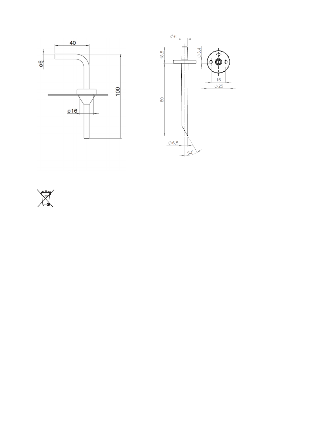
MONTAGE / ABMESSUNG
INSTALLATION / DIMENSIONS
BEFESTIGUNG & SCHLAUCHANSCHLUSS
MOUNTING & HOSE CONNECTION
WICHTIG: Schläuche dürfen beim Anschließen und Verlegen nicht geknickt oder beschädigt
werden. Undichte Schläuche und Schlauchanschlüsse verursachen Störungen am Gerät oder
liefern falsche Messergebnisse.
Øinnen = < 3,5 / 5,5 mm für optimale Klemmung. Ab 25 kPa Schlauchklemme verwenden.
P1 = Überdruckmessung
P2 = Unterdruckmessung
P1 & P2 = Differenzdruckmessung
IMPORTANT: Pressure hoses may not be bent or damaged during installation. Leaking hoses
and hose connections will cause errors on the device or inaccurate measurements.
IInner Ø= < 3,5 / 5,5 mm for optimal clamping. From 25 kPa hose clamps must be used.
P1 = positive pressure measurement
P2 = negative pressure measurement
P1 & P2 = Differential pressure measurement
Elektrische Anlagen dürfen nur
durch autorisierte Elektrofachkräfte
errichtet, erweitert, geändert und in
Stand gehalten werden.
Electrical equipment may only be
installed, added to, changed or
maintained by authorized
electricians.
Der Differenzdruck-Messumformer kann in beliebiger Einbaulage montiert werden. Die
selbstkompensierende Piezo-Messzelle eliminiert Lagefehler.
The differential pressure transducer can be mounted in any position. The self-compensating piezo-
load cells eliminate errors due to positioning.
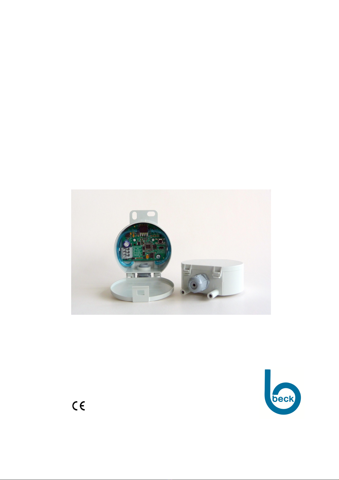
KLEMMENBELEGUNG
TERMINAL CONNECTION
TECHNISCHE DATEN / TECHNICAL DATA
Versorgungsspannung
Supply Voltage
18...24...30 VAC und/and 18...24...30 VDC
Ausgangssignal
Output signal
0...10 V oder/or 4...20 mA / 3-wire
Bürde für Ausgang 4…20 mA
Working resistance for 4…20 mA
20...500 Ω
Max. Stromaufnahme
Max. current draw
< 40 mA
Druckmedium
Pressure medium
Luft und nicht aggressive Gase
Air and non aggressive gases
Messverfahren
Measuring process
Piezoresistiver Drucksensor
Piezoresistive pressure transducer
Linearitäts- u. Hysteresefehler
Linearity and hysteresis error
≤± 1 % v. EW
≤± 1 % of FSD
Betriebstemperatur
Operating temperature
0...50 °C
Lagertemperatur
Storage temperature
-10...70 °C
Langzeitstabilität, typ.
Long term stability, typ.
≤± 0,5 % bis ± 2,5 % v. EW/Jahr, je nach Druckbereich
≤± 0,5 % bis ± 2,5 % of FSD/year, dep. pressure range
Wiederholgenauigkeit
Repeatability
≤± 0,2 % v. EW
≤± 0,2 % of FSD
Lageabhängigkeit
Position dependency
≤± 0,02 % v. EW/g
≤± 0,02 % of FSD/g
3Masse GND
Ground GND
2Ausgangssignal 0…10 V/4…20 mA
Output signal 0…10 V/4…20 mA
1Versorgungsspannung 18...30 VAC/VDC
Supply voltage 18...30 VAC/VDC

Feuchte
Humidity
0...95 % rel., nicht kondensierend
0...95 % rel., non condensing
Ansprechzeit, umschaltbar
Response time, selectable
1 s oder/or 100 ms
Prozessanschluss
Pressure connection
6 mm Schlauchstutzen
6 mm hose connection
Elektrischer Anschluss
Electrical connection
Federklemmen für Drähte und Litzen bis 1,5 mm2
Spring connector for cable and leads up to 1.5 mm
2
Befestigung
Mounting
Schraubbefestigung mit Kerbschrauben
Screw fastening with sheet metal screws
Gehäusematerial
Casing material
ABS
Gehäuseabmessunge
n
Casing dimensions
Ø 66 x 28 mm
Gewicht
Weight
50 g
Schutzart nach EN60529
Protection to EN 60529
IP 54
Kabeldurchführung
Cable conduit
M12x1,5 Polyamid
Normen / Konformität
Standards / Conformity
EN 60770, EN 61326, 2011/65/EWG (RoHS II)
ZUBEHÖR
Artikel-Nr.
ACCESSORIES
Article No.
Climaset® bestehend aus 2 m PVC-Schlauch und 2 Kunststoffnippeln 6555
Climaset® consisting of 2 m PVC tubing and 2 plastic tubes
Climaset® bestehend aus 2 m Silikon-Schlauch und 2 Kunststoffnippeln 6557
Climaset® consisting of 2 m silicon tubing and 2 plastic tubes
Climaset® bestehend aus 2 m PVC-Schlauch und 2 abgewinkelten Metallröhrchen 6550
Climaset® consisting of 2 m PVC tubing and 2 angled metal tubes
Climaset® bestehend aus 2 m Silikon-Schlauch und 2 abgewinkelten Metallröhrchen 6556
Climaset® consisting of 2 m silicon tubing and 2 angled metal tubes
Kanalanschlussnippel für Climaset® 6555 6551
Duct connecting pipe for Climaset® 6555
Abgewinkeltes Metallrohr für Climaset® 6550 6552
Angled metal pipe for Climaset® 6550
Gummitülle für Metallrohr Climaset® 6550 6553
Rubber grommet for Climaset® 6550
Rolle mit 100 m PVC-Schlauch 6424
Roll with 100 m PVC tubing
Rolle mit 100 m Silikon-Schlauch 6425
Roll with 100 m silicon tubing
8.930.108 DMU982R Stand 06. 2014
Climaset®6550 / 6556 Climaset®6555 / 6557
ENTSORGUNG
DISPOSAL
Die durchgestrichene Mülltonne auf diesem Produkt weist Sie darauf hin, dass das Produkt am
Ende seiner Lebensdauer getrennt vom Hausmüll entsorgt werden muss. Bitte bringen Sie alle
elektronischen Geräte zu den eingerichteten kommunalen Sammelstellen in Ihrer Gemeinde.
The crossed out wheeled bin symbol on the product reminds you of your obligation, that
when you dispose of the appliance, it must be separately collected. Consumers should
contact their local authority or retailer for information concerning the correct disposal of their
old appliance.
Download der Konformitätserklärung unter:
www.beck-sensors.com
Table of contents
Other Beck Transducer manuals


Popular Transducer manuals by other brands

Comet
Comet T4111 instruction manual

Camille Bauer
Camille Bauer Gossen MetraWatt SINEAX DME 401 operating instructions

HYDACELECTRONIC
HYDACELECTRONIC HLT 1100 Series Assembly instructions

B-K Medical
B-K Medical Type 8506-S user guide

Hervisa Perles
Hervisa Perles VOLTO Series Operator's manual

Setra Systems
Setra Systems 470 manual


Thermo Electron
Thermo Electron Brandt STD5000 Series manual

Clark Synthesis
Clark Synthesis TACTILE SOUND AW339 installation guide

MKS
MKS MicroPirani 925 Series Short form manual

Milltronics
Milltronics PL-590 instruction manual

DATUM ELECTRONICS
DATUM ELECTRONICS M425 Handbook & installation guide

MKS
MKS UniMag 971B Operation and installation manual