Beck 984A Series User manual

1 - 8
984A / 984Q
Kompakte Luft- / Differenzdruck-Messumformer
mit auswählbaren Druckmessbereichen und
automatischem Nullpunkt-Abgleich
- Gebäudeautomation, Klima- & Reinraumtechnik
- Ventil- & Klappensteuerung
- Filter-, Ventilatoren- & Gebläseüberwachung
- Kontrolle von Luftströmungen
Compact Air- / Differential Pressure Transducer
with selectable pressure ranges and automatically
zero calibration
- Building automation, air-conditioning & clean room technology
- Valve & shutter control
- Filter, ventilator & fan monitoring
- Air-flow control
SICHERHEIT & PRODUKTHAFTUNG
SAFETY & LIABILITY
Das in dieser Anleitung aufgeführte Produkt darf nur von ausgebildeten Fachleuten montiert, angeschlossen und
in Betrieb genommen werden. Die geltenden Sicherheitsbestimmungen, Verwendungszweck und technischen
Daten sind unbedingt einzuhalten. Gemäß diesen Bestimmungen müssen Anlagen spannungsfrei geschaltet und
vor unbeabsichtigtem Wiedereinschalten gesichert werden. Beschädigte Produkte dürfen nicht verwendet
werden. Das Produkt darf nicht für U.S. FDA kontrollierte Anwendungsbereiche verwendet werden. Für Schäden,
die durch unsachgemäße Verwendung entstehen, z.B. Demontage der Platine, Ab-/ Aufstecken der
Displaybaugruppe oder Beschädigung des Gehäuses, wird keine Haftung übernommen.
The product mentioned in this manual can only be installed, connected and put into operation by trained
professionals. The existing safety regulations, the intended use and the technical data
must be strictly observed.
According to these regulations, plants must be zero
-potential and secured against inadvertently restart. Damaged
products cannot be used. The product cannot be used for U.S. FDA controlled application areas. For damage
caused by improper use no liability is assumed. Disassembling the electronic board / display module or damage
the housing will void the warranty.
ELEKTRISCHER ANSCHLUSS
ELECTRICAL CONNECTION
GEFAHR DURCH STROMSCHLAG: Bei Arbeiten an der Elektrik darf keine Spannung anliegen. Durchführung
der Arbeiten entsprechend den gesetzlichen Vorschriften vornehmen. Kabelisolierung muss für Dichtigkeit in
Gehäuse eingeführt werden. Passende Klingenbreite für Klemmschrauben verwenden.
DANGER OF ELECTRIC SHOCK: No voltage must be applied if you work on electric systems. Carry out the
service work according to legal rules. Cable insulation must be done into the housing in a way that tightness is
preserved. Use a matching screwdriver for the clamping screws.
ENTSORGUNG
DISPOSAL
Die meisten unserer Produkte enthalten wertvolle Rohstoffe und sollten deshalb einem geordneten Recycling zugeführt werden.
Bitte beachten Sie die geltenden nationalen Vorschriften, Gesetze und Regelungen.
Most of our products may contain valuable materials that should be recycled and not disposed of as domestic waste. Please
observe the applicable relevant regulations and laws.

2 - 8
TECHNISCHE DATEN
TECHNICAL DATA
Versorgungsspannung Supply Voltage 18...30 VAC / DC
Ausgangssignal* Output signal* 0...10 V oder/or 4...20 mA
Bürde für Ausgang
4…20 mA
Working resistance for
output 4…20 mA 20...500 Ω
Bürde für Ausgang
0…10 V
Working resistance for
output 0…10 V ≥1kΩ(≤10 mA)
Max. Stromaufnahme Max. current draw < 190 mA
Druckmedium Pressure medium Luft und nicht aggressive Gase
Air and non aggressive gases
Messverfahren Measuring process Piezoresistiver Drucksensor
Piezoresistive pressure transducer
Linearität
(inkl. Hysterese und
Reproduzierbarkeit)
Linearity
(incl. hysteresis and
repeatability) ≤±0,5% FS, min. ±1 Pa / ≤±0.5% FS, min. ±1 Pa
Unsicherheit
(Gesamtfehler ohne
Langzeit- und
Temperatureinfluss)
Uncertainty
(Total Error Band w/o long-
term and temperature
effects)
±1% FS, min. ±1 Pa
Langzeitstabilität Long-term stability n.r.
Betriebs- und
Lagertemperatur Working and storage
temperature -10...50 °C (14…122 °F)
Schaltausgang Switching output NPN NO
Anzeige (optional) Display (optional) LED rot 7-segment 4-stellig
LED red 7-segment 4 digits
Offsetabgleich Zero calibration Automatisch / Automatically
Feuchte Humidity 0...95 % rel., nicht kondensierend
0...95 % rel., non condensing
Ansprechzeit, umschaltbar*
Response time, selectable* 1 s oder 200 ms
1 s or 200 ms
Prozessanschluss Pressure connection 6 mm Schlauchstutzen / 6 mm hose connection
Elektrischer Anschluss Electrical connection Schraubklemmen für Drähte und Litzen bis 1,5 mm
2
Screw terminal for cable and leads up to 1.5 mm2
Befestigung Mounting
Schraubbefestigung mit Kerbschrauben
Screw fastening with sheet metal screws
Gehäusematerial Casing material ABS
Gehäuseabmessungen Casing dimensions 85 x 58 mm
Gewicht Weight ca. 145 gr / appr. 145 g
Schutzart nach EN60529 Protection to EN 60529 IP 54 mit Schutzhaube oder IP00 ohne Schutzhaube
IP 54 with protection cap or IP00 without protection cap
Kabeldurchführung Cable conduit
Hutmutterverschraubung SW20 aus Polyamid oder
Kabeldurchführung M20x1,5
Cap nut conduit AF20 made of polyamide or
cable conduit M20x1.5
Normen / Konformität Standards / Conformity EN 61326 (CE), 2011/65/EWG (RoHS II)
Genauigkeitsangaben nach EN 60770 bezogen auf die Druckmessung bei 23°C
Accuracy specifications according to EN 60770 based on the pressure measurement at 23°C
*weitere Ausführung / Werte auf Anfrage. Further version / values on request.
3 - 8
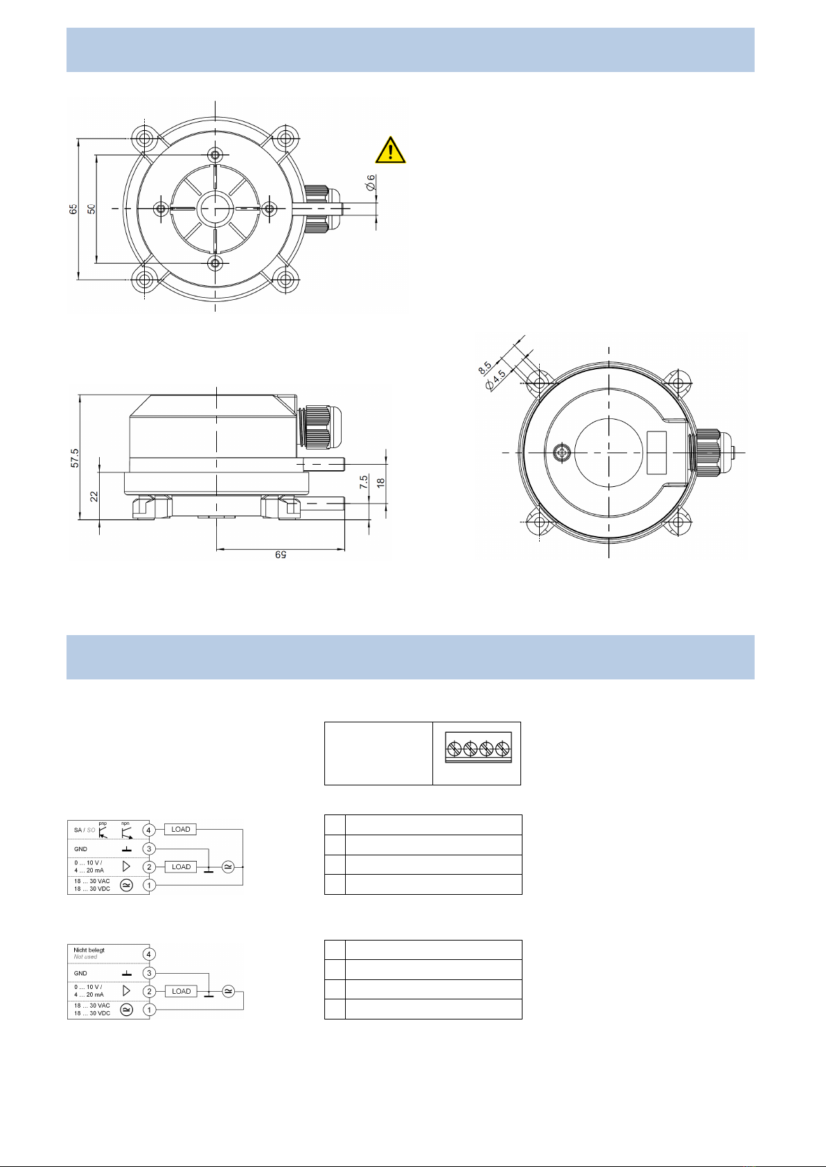
MONTAGE / ABMESSUNG
INSTALLATION / DIMENSIONS
Elektrische Anlagen dürfen nur durch autorisierte
Elektrofachkräfte errichtet, erweitert, geändert und in Stand
gehalten werden.
Electrical equipment may only be installed, added to,
changed or maintained by authorised electricians.
Der Differenzdruck-Messumformer kann in beliebiger
Einbaulage montiert werden. Die selbstkompensierende
Piezo-Messzelle eliminiert Lagefehler.
The differential pressure transducer can be mounted in any
position. The self
-compensating piezo-load cells eliminate
errors due to positioning.
KLEMMENBELEGUNG
TERMINAL CONNECTION
3-Leiter mit Schaltausgang
3-wire with switching output
3-Leiter ohne Schaltausgang
3-wire without switching output
4 Schaltausgang (SA)
Switching output (SO)
3 Masse (GND)
Ground (GND)
2 Ausgangssignal (0…10 V / 4…20 mA)
Output signal (0…10 V / 4…20 mA)
1 Versorgungsspannung (18...30 VAC / VDC)
Supply voltage (18...30 VAC / VDC)
4 Nicht belegt
Not used
3 Masse (GND)
Ground (GND)
2 Ausgangssignal (0…10 V / 4…20 mA)
Output signal (0…10 V / 4…20 mA)
1 Versorgungsspannung (18...30 VAC / VDC)
Supply voltage (18...30 VAC / VDC)
Schraubklemme
4-polig
Plug-in terminals
4-pole
12 34

4 - 8
TASTEN UND JUMPERBELEGUNG
SWITCHES AND JUMPER SETTINGS
Die Funktionseinstellungen des Differenzdruck-Messumformers lassen sich durch das Stecken von Jumpern im Inneren des
Umformers anpassen.
The function settings of differential pressure transducer are achieved by inserting jumpers appropriately within the transducer.
984A
984Q
OFFSETABGLEICH
ZERO CALIBRATION
Der Druckmessumformer führt regelmäßig bei Bedarf automatisch einen Nullpunktabgleich durch.
If required the transmitter performs automatically a zero calibration.

5 - 8
ANALOGAUSGANGSSIGNAL
ANALOG OUTPUT SIGNAL
Linear (Jumper 3 gesteckt) / Linear (Jumper 3 plugged in) Radiziert (Jumper 3 geöffnet) / Square root (Jumper 3 open)
0 –10 V 0 –10 V
4 –20 mA 4 –20 mA
SCHALTAUSGANG
SWITCH OUTPUT
Der Differenzdruck-Messumformer verfügt über einen einstellbaren Transistor-Schaltausgang mit einer maximalen Schaltfähigkeit
von 30VDC/100 mA. Mit dieser Funktion setzen Sie für einen definierten Druck den Schaltausgang auf 'Durchgeschaltet'.
The transmitter has an adjustable transistor switching output with a maximum switching capacity of 30 Vdc/100 mA. This function
is used to set the switching output to ‘switched through’for a pressure level you have defined.
PROGRAMMIERUNG /
PROGRAMMING:
•
Ohne LED Anzeige /
Without LED Display
Taster /
Button
Legen Sie den Druck oder die Druckdifferenz an, bei welcher der Schaltausgang
durchgeschaltet werden soll. Drücken Sie dann den Taster „S“(SET) für 5 Sekunden bis die
LED schnell blinkt um den Wert zu speichern. Die LED leuchtet sobald der definierte Druck
erreicht oder überschritten wird.
Apply the pressure or pressure differential at which the switching output needs to be switched
through. Then press the button „S“(SET) for 5 sec. until the LED flashes quickly (= value is
saved). The LED lights up as soon as the defined pressure level is reached or exceeded.
LED für SA
LED for SO
•
Mit LED
-
Anzeige /
With LED
-
Display
ØSiehe Programmierung über LED Anzeige / see programming via LED Display
Werkseinstellung: Hysterese für Schaltausgang ist standard auf 0,5% vom Endwert eingestellt, weitere Werte auf Anfrage.
Default: Hysteresis for switching output is standard set at 0.5% of full scale, other values on request.

6 - 8
PROGRAMMIERUNG ÜBER LED ANZEIGE für Ausführung mit Schaltausgang
PROGRAMMING VIA LED DISPLAY for version with switching output
ØAktueller Messwert
Current measurand
Press M (MODE)
ØEinstellung des Schaltpunktes
Set switch point
Press M (MODE) Press S (SET)
üAnzeige des aktuellen Schaltpunktes
Current switch point is displayed
Press S (SET) >5 sec
üAnpassen des Schaltpunktes
Modify current switch point
Press M (MODE)
üSchaltpunkt speichern, Anzeige blinkt
Save switch point, display is blinking
Press M (MODE)
ØSpitzenwert max.
Max. peak value
Press M (MODE) Press S (SET)
üAnzeige Spitzenwert max.
Max. peak value is displayed
Press M (MODE)
üBestätigung
Confirmation
Press M (MODE)
ØSpitzenwert min.
Min. peak value
Press M (MODE) Press S (SET)
üAnzeige Spitzenwert min.
Min. peak value is displayed
Press M (MODE)
üBestätigung
Confirmation
Press M (MODE)
ØAktueller Messwert
Current measurand

7 - 8
BESTELLMATRIX 984 X
. X
X
X
X
X
4b
ORDER MATRIX
I II
III
IV
V
VI
VII
I
Baureihe /
Series
Bestell
-
Code
Order code
2 Druckmessbereiche / 2 pressure ranges A
8 Druckmessbereiche / 8 pressure ranges Q
I
I
Schutzart IP
54
/
Protection category IP54
mit Kabeldurchführung M20x1,5 / with cable conduit M20x1.5 3
mit Hutmutterverschraubung SW20 / with cap nut conduit AF20 5
II
I
Auswählbare Druckmessbereiche
/
Selectable pressure ranges
98
4
A mit 2 Druckbereichen /
with 2 pressure ranges
±25 Pa (±0,25 mbar) / (±0.25 mbar) E
±50 Pa (±0,5 mbar) / (±0.5 mbar) X
±100 Pa (±1,0 mbar) / (±1.0 mbar) W
0…25 Pa (0…0,25 mbar) / (0…0.25 mbar) 0…50 Pa (0…0,5 mbar) / (0…0.5 mbar) 0
0…50 Pa (0…0,5 mbar) / (0…0.5 mbar) 0…100 Pa (0…1,0 mbar) / (0…1.0 mbar) 1
0…100 Pa (0…1,0 mbar) / (0…1.0 mbar) 0…250 Pa (0…2,5 mbar) / (0…2.5 mbar) 2
0…250 Pa (0…2,5 mbar) / (0…2.5 mbar) 0…500 Pa (0…5,0 mbar) / (0…5.0 mbar) 3
0…500 Pa (0…5,0 mbar) / (0…5.0 mbar) 0…1000 Pa (0…10 mbar) / (0…10 mbar) 4
0…1 kPa (0…10 mbar) /(0…10 mbar) 0…2,5 kPa (0…25 mbar) / (0…25 mbar) 5
0…5 kPa (0…50 mbar) /(0…50 mbar) 0…10 kPa (0…100 mbar) / (0…100 mbar) 7
0…25 kPa (0…250 mbar) /(0…250 mbar) 0…50 kPa (0…500 mbar) / (0…500 mbar) 9
0…50 kPa (0…500 mbar) /(0…500 mbar) 0…100 kPa (0…1 bar) / (0…1 bar) A
98
4
Q mit 8 Druckbereichen /
with 8 pressure ranges
±50 Pa
(±0,5 mbar) / (±0.5 mbar)
±100 Pa
(±1,0 mbar) / (±1.0 mbar)
±250 Pa
(±2,5 mbar) / (±2.5 mbar)
±500 Pa
(0…5,0 mbar) / (0…5.0 mbar)
0…100 Pa
(0…1,0 mbar) / (0…1.0 mbar)
0…250 Pa
(0…2,5 mbar) / (0…2.5 mbar)
0…500 Pa
(0…5,0 mbar) / (0…5.0 mbar)
0…1000 Pa
(0…10 mbar) / (0…10 mbar) 4
±100 Pa
(±1,0 mbar) / (±1.0 mbar)
0…100 Pa
(0…1,0 mbar) / (0…1.0 mbar)
0…200 Pa
(0…2,0 mbar) / (0…2.0 mbar)
0…500 Pa
(0…5,0 mbar) / (0…5.0 mbar)
0…1000 Pa
(0…10 mbar) / (0…10 mbar)
0…1500 Pa
0…15 mbar) / 0…15 mbar)
0…2000 Pa
0…20 mbar) / 0…20 mbar)
0…2500 Pa
(0…25 mbar) / (0…25 mbar) 5
IV
Druckeinheit
* /
Pressure unit*
mbar 1
Pascal 3
V
Ausgangssignal und Versorgung
* /
Output signal and supply*
0 …10 V / 4 …20 mA, 3-Leiter, linear, mit Schaltausgang
0 …10 V / 4 …20 mA, 3-wire, linear, with switching output 1
0 …10 V / 4 …20 mA, 3-Leiter, linear, ohne Schaltausgang
0 …10 V / 4 …20 mA, 3-wire, linear, without switching output 7
4 …20 mA / 0 …10 V, 3-Leiter, linear, mit Schaltausgang
4 …20 mA / 0 …10 V, 3-wire, linear, with switching output 3
4 …20 mA / 0 …10 V, 3-Leiter, linear, ohne Schaltausgang
4 …20 mA / 0 …10 V, 3-wire, linear, without switching output D
VI
Anzeige
/
Display
ohne LED Anzeige / without LED display 0
mit LED Anzeige / with LED display 1
VI
I
Elektrischer Anschluss
/
Electrical connection
über Schraubklemmen / using screw terminal block 4b
Fettgedruckte Bezeichnungen sind im Lieferzustand ab Werk eingestellt. / Factory settings printed in bold type.
*weitere Ausführungen auf Anfrage. / Further versions upon request.

8 - 8
DRUCKMESSBEREICHE
PRESSURE RANGES
Baureihe
Model
Bereich 1
Range1
Bereich 2
Range2
Überdruck
Sicherheit
Over pressure
safety
Berstdruck
Burst
pressure
Zusätzliche Unsicherheit durch
Temperatur [% FS/10K]
Additional uncertainty with
temperature [% FS/10K]
984A.3E3 ±25 Pa - 60 kPa 100 kPa ± 0,7 / ± 0.7
984A.3X3 ±50 Pa - 60 kPa 100 kPa ± 0,5 / ± 0.5
984A.3W3 ±100 Pa - 60 kPa 100 kPa ± 0,3 / ± 0.3
984A.303 0 …25 Pa 0 …50 Pa 60 kPa 100 kPa ± 0,7 / ± 0.7
984A.313 0 …50 Pa 0 …100 Pa 60 kPa 100 kPa ± 0,5 / ± 0.5
984A.323 0 …100 Pa 0 …250 Pa 60 kPa 100 kPa ± 0,3 / ± 0.3
984A.333 0 …250 Pa 0 …500 Pa 60 kPa 100 kPa n.r. /
n.r.
984A.343 0 …500 Pa 0 …1000 Pa 75 kPa 125 kPa n.r. /
n.r.
984A.353
0 …1 kPa 0 …2,5 kPa 85 kPa 135 kPa n.r. /
n.r.
984A.373
0 …5 kPa 0 …10 kPa 85 kPa 135 kPa n.r. /
n.r.
984A.393
0 …25 kPa 0 …50 kPa 200 kPa 400 kPa n.r. /
n.r.
984A.3A3
0 …50 kPa 0 …100 kPa 200 kPa 400 kPa n.r. /
n.r.
Baureihe
Model
Schalter
Position
Switch
position
Druckmessbereich
Pressure range
Überdruck
Sicherheit
Over pressure
safety
Berstdruck
Burst
pressure
Zusätzliche Unsicherheit durch
Temperatur [% FS/10K]
Additional uncertainty with
temperature [% FS/10K]
984Q.343
1
0 …100 Pa ( 1,0 mbar) 75 kPa 125 kPa ± 0,7 / ± 0.7
2
0 …250 Pa ( 2,5 mbar) 75 kPa 125 kPa ± 0,3 / ± 0.3
3
0 …500 Pa ( 5,0 mbar) 75 kPa 125 kPa n.r. / n.r.
4
0 …1000 Pa ( 10 mbar) 75 kPa 125 kPa n.r. / n.r.
5
± 50 Pa (± 0,5 mbar) 75 kPa 125 kPa ± 0,7 / ± 0.7
6
± 100 Pa (± 1,0 mbar) 75 kPa 125 kPa ± 0,3 / ± 0.3
7
± 250 Pa (± 2,5 mbar) 75 kPa 125 kPa n.r. /
n.r.
8
± 500 Pa (± 5,0 mbar) 75 kPa 125 kPa n.r. /
n.r.
984Q.353
1
± 100 Pa (± 1,0 mbar) 85 kPa 135 kPa ± 1,0 / ± 1.0
2
0 …100 Pa ( 1,0 mbar) 85 kPa 135 kPa ± 1,5 / ± 1.5
3
0 …200 Pa ( 2,0 mbar) 85 kPa 135 kPa ± 1,0 / ± 1.0
4
0 …500 Pa ( 5,0 mbar) 85 kPa 135 kPa ± 0,5 / ± 0.5
5
0 …1000 Pa ( 10 mbar) 85 kPa 135 kPa ± 0,3 / ± 0.3
6
0 …1500 Pa ( 15 mbar) 85 kPa 135 kPa n.r. / n.r.
7
0 …2000 Pa ( 20 mbar) 85 kPa 135 kPa n.r. /
n.r.
8
0 …2500 Pa ( 25 mbar) 85 kPa 135 kPa n.r. /
n.r.
Zusatzfunktion
Lo
Festes Ausgangssignal / fixed output signal 0 V / 4 mA
Hi
Festes Ausgangssignal / fixed output signal 10 V / 20 mA
Weitere Druckmessbereiche auf Anfrage / Further pressure ranges upon request.
OPTIONALES ZUBEHÖR
OPTIONAL ACCESSORIES
Artikel-Nr.
Article No.
Climaset
®
bestehend aus 2 m PVC-Schlauch und 2 Kunststoffnippeln
Climaset®consisting of 2 m PVC tubing and 2 plastic tubes 6555
Climaset
®
bestehend aus 2 m Silikon-Schlauch und 2 Kunststoffnippeln
Climaset® consisting of 2 m silicon tubing and 2 plastic tubes 6557
Climaset
®
bestehend aus 2 m PVC-Schlauch und 2 abgewinkelten Metallröhrchen
Climaset®consisting of 2 m PVC tubing and 2 angled metal tubes 6550
Climaset
®
bestehend aus 2 m Silikon-Schlauch und 2 abgewinkelten Metallröhrchen
Climaset®consisting of 2 m silicon tubing and 2 angled metal tubes 6556
Kanalanschlussnippel für Climaset
®
6555
Duct connecting pipe for Climaset®6555 6551
Abgewinkeltes Metallrohr für Climaset
®
6550
Angled metal pipe for Climaset
®6550 6552
Gummitülle für Metallrohr Climaset
®
6550
Rubber grommet for Climaset®6550 6553
Rolle mit 100 m PVC-Schlauch
Roll with 100 m PVC tubing 6524
Rolle mit 100 m Silikon-Schlauch
Roll with 100 m silicon tubing 6525
8.930.084-3
984A_984Q manual german_english 8.930.084
-
3
Te
chnische Änderungen
vorbehalten
/
Technical data subject to change without prior notice
.
Copyright© 201
9
Beck GmbH
This manual suits for next models
13
Table of contents
Other Beck Transducer manuals


Popular Transducer manuals by other brands


Barksdale
Barksdale UTA 2 operating instructions

Veris Industries
Veris Industries PWR Series installation guide

controlair
controlair 595XP Installation, operation and maintenance instructions

S+S Regeltechnik
S+S Regeltechnik Thermasgard RTM Operating Instructions, Mounting & Installation

Campbell
Campbell CS451 instruction manual

HBM
HBM Z8 Mounting instructions


