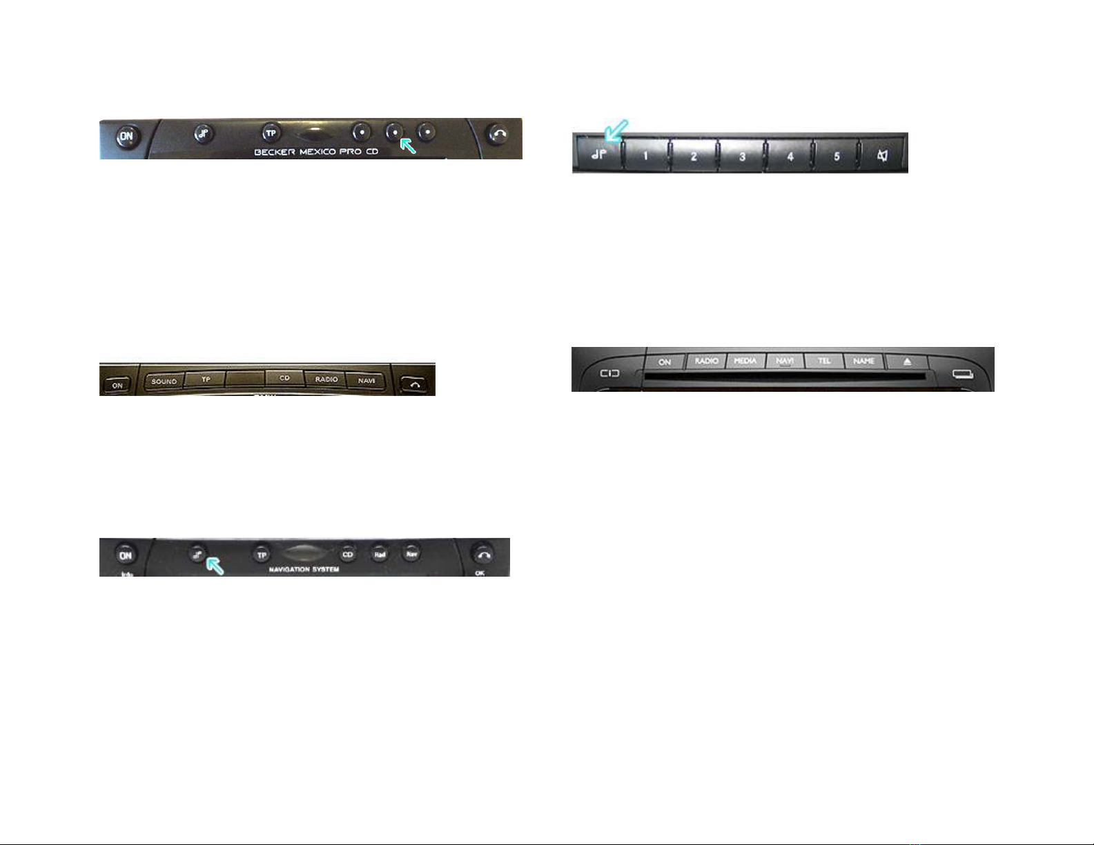
Radios wit 3 Function buttons (i.e. BE4527)
Radios wit 3 Function buttons (i.e. BE4527)Radios wit 3 Function buttons (i.e. BE4527)
Radios wit 3 Function buttons (i.e. BE4527)
1. Turn radio ON.
2. Press and old Function button #2 (center) for more t an 4
seconds.
3. T e accompanying menu appears on t e display.
4. Press t e multifunction button located directly under “AUX”
on t e display to c ange t e present setting from OFF to ON.
5. T e Setting is stored automatically.
Nav Traffic Radios
Nav Traffic RadiosNav Traffic Radios
Nav Traffic Radios
1. Press t e "Radio" button to enter Radio mode.
2. Press t e "Navi" and "F10" simultaneously
3. Press "Next" until t e AUX input, C anger Res screen
4. Press AUX to enable/disable.
Becker 4775 (LandRover) & Ot er Traffic
Becker 4775 (LandRover) & Ot er TrafficBecker 4775 (LandRover) & Ot er Traffic
Becker 4775 (LandRover) & Ot er Traffic
Pro
ProPro
Pro
1. Wit t e Radio "ON" press and old t e Tone button until
t e sub-menu comes up.
2. Press t e soft-key labeled “Aux” until t e screen displays
“AUX Mode on”.
3. Press t e Tone button to exit t e menu.
4. To enter "AUX" mode, press t e "CD" button and select t e
"AUX" soft-key.
Sound 5 (BE7077 Sprinter Van)
Sound 5 (BE7077 Sprinter Van)Sound 5 (BE7077 Sprinter Van)
Sound 5 (BE7077 Sprinter Van)
1. Turn radio ON.
2. Press t e
dp
dpdp
dp
repeatedly until EXT menu appear.
3. Turn Rotary control knob clockwise and select EXT AUX.
4. Press t e CD button repeatedly until “AUX” is displayed
Cascade Pro (i.e. BE7941)
Cascade Pro (i.e. BE7941)Cascade Pro (i.e. BE7941)
Cascade Pro (i.e. BE7941)
To activate t e External Device mode
To activate t e External Device mode To activate t e External Device mode
To activate t e External Device mode
1. Turn radio ON.
2. Press t e information button
3. Turn t e rotary control/pus (OK) button counterclockwise
until System Settings appears at t e top rig t of t e display
4. Press t e rotary control/pus (OK) button
5. Turn t e rotary control /pus (OK) button to select External
Device
6. Confirm selection by pressing t e rotary control/pus (OK)
button
7. Select “AUX” from list and turn it “ON”.
8. Exit menu
9. To listen to t e “AUX” device, press t e MEDIA button
10. Turn t e rotary control /pus (OK) button to “AUX” and
press t e rotary control/pus (OK) button