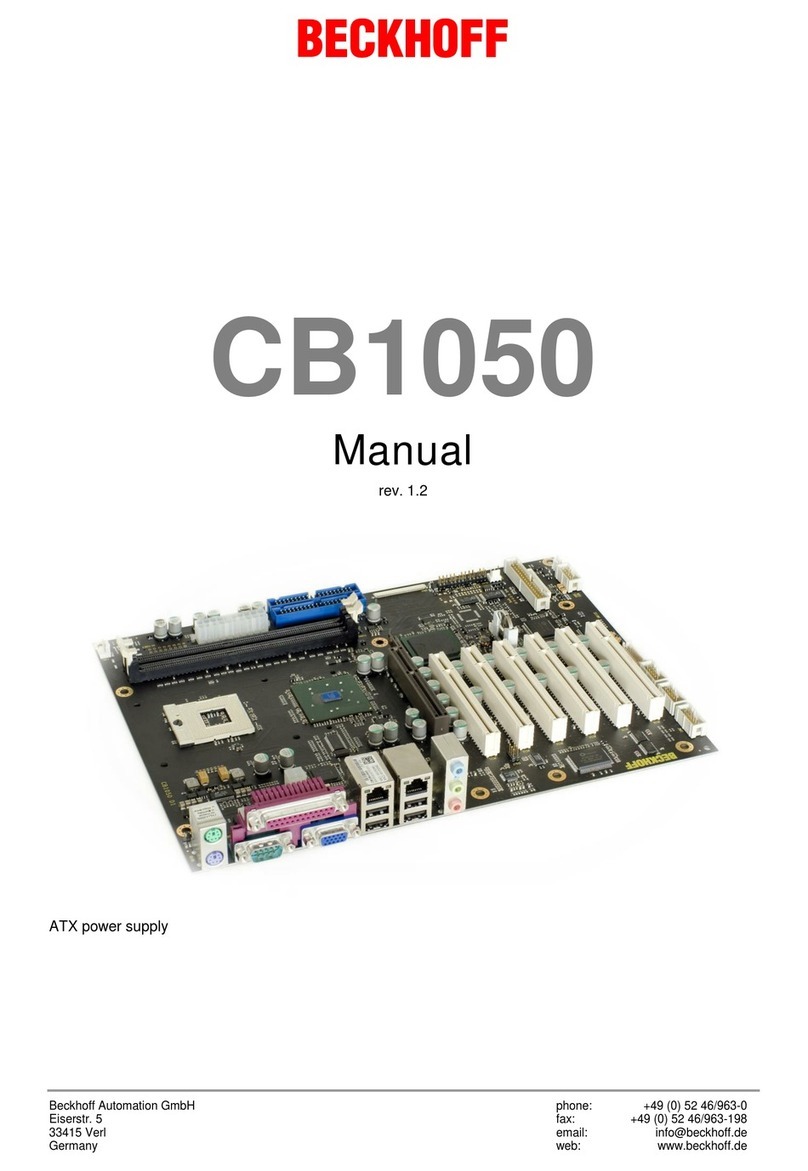
Beckhoff CB1052 User manual

Beckhoff AutomationGmbH phone: +49(0)5246/963-0
Eiserstr.5 fax: +49(0)5246/963-198
33415Verl email: info@beckhoff.de
Germany web: www.beckhoff.de
CB1052
Manual
rev0.1
ATXpowersupply


Contents
Beckhoff NewAutomation Technology CB1052 page 3
Contents
0DocumentHistory...........................................................................................................................6
1Introduction.....................................................................................................................................7
1.1 Noteson the Documentation..................................................................................................7
1.1.1 LiabilityConditions.............................................................................................................7
1.1.2 Copyright...........................................................................................................................7
1.2 SafetyInstructions..................................................................................................................8
1.2.1 Disclaimer..........................................................................................................................8
1.2.2 Description of SafetySymbols............................................................................................8
1.3 EssentialSafetyMeasures.....................................................................................................9
1.3.1 Operator'sObligation toExerciseDiligence........................................................................9
1.3.2 National RegulationsDepending on the Machine Type.......................................................9
1.3.3 OperatorRequirements......................................................................................................9
1.4 FunctionalRange.................................................................................................................10
2Overview......................................................................................................................................11
2.1 Features...............................................................................................................................11
2.2 Specificationsand Documents..............................................................................................13
3Connectors...................................................................................................................................14
3.1 PowerSupply, SystemConnectors, CPU..............................................................................14
3.1.1 PowerSupply...................................................................................................................14
3.1.2 System.............................................................................................................................16
3.1.3 CPUSocket.....................................................................................................................17
3.1.4 CMOSbattery..................................................................................................................18
3.2 Back Panel Connectors........................................................................................................19
3.2.1 PS/2keyboardand mouse...............................................................................................19
3.2.2 Parallelport,serialports, VGA..........................................................................................20
3.2.3 USB and LAN...................................................................................................................22
3.2.4 Audioconnectors.............................................................................................................23
3.3 SATA, PATA,FDD,Memory.................................................................................................24
3.3.1 IDEinterface....................................................................................................................24
3.3.2 SATAinterfaces...............................................................................................................25
3.3.3 Floppyinterface................................................................................................................26
3.3.4 Memory............................................................................................................................28
3.4 InternalConnectors..............................................................................................................31
3.4.1 USB 5-12.........................................................................................................................31
3.4.2 Serial portsCOM2toCOM4.............................................................................................32
3.4.3 LVDS...............................................................................................................................33
3.4.4 TV-Out.............................................................................................................................35
3.4.5 CD-In...............................................................................................................................36
3.4.6 S/PDIF.............................................................................................................................37
3.4.7 PCIinterfaces..................................................................................................................38
3.4.8 PCI-express interfaces(x1)..............................................................................................40
3.4.9 PCI-express interface(x16)..............................................................................................41
3.4.10 SMB/I2C......................................................................................................................44
3.4.11 Fan Connectors...........................................................................................................45
3.5 JumperSettings...................................................................................................................46
3.5.1 ClearCMOS.....................................................................................................................46

Contents
page 4 Beckhoff NewAutomation Technology CB1052
3.5.2 Jumper: KeyboardPower(KBPWR).................................................................................47
4BIOSSettings...............................................................................................................................48
4.1 RemarksforSetup Use........................................................................................................48
4.2 Top LevelMenu....................................................................................................................48
4.3 StandardCMOSFeatures....................................................................................................49
4.3.1 SATAchannels................................................................................................................50
4.3.2 PATAchannel..................................................................................................................51
4.4 Advanced BIOSFeatures.....................................................................................................52
4.4.1 CPUFeature....................................................................................................................54
4.4.2 HardDiskBoot Priority.....................................................................................................55
4.5 Advanced Chipset Features..................................................................................................56
4.5.1 PCI Express Root PortFunction.......................................................................................58
4.6 Integrated Peripherals..........................................................................................................59
4.6.1 OnChipIDEDevices........................................................................................................60
4.6.2 OnboardDevices.............................................................................................................62
4.6.3 SuperIO Devices..............................................................................................................63
4.6.4 USB DeviceSetting..........................................................................................................64
4.7 PowerManagement Setup...................................................................................................65
4.7.1 PCI Express PM Function.................................................................................................67
4.7.2 Intel DTSFeature.............................................................................................................68
4.8 PnP/PCIConfiguration..........................................................................................................69
4.8.1 IRQ Resources.................................................................................................................71
4.9 PCHealthStatus..................................................................................................................72
4.10 Frequency/Voltage Control...................................................................................................73
4.11 Load Fail-SafeDefaults........................................................................................................74
4.12 Load Optimized Defaults......................................................................................................74
4.13 Set Password.......................................................................................................................74
4.14 Save&Exit Setup................................................................................................................74
4.15 ExitWithout Saving..............................................................................................................74
5BIOSupdate.................................................................................................................................75
6Mechanical Drawing......................................................................................................................76
6.1 PCB: Mounting Holes...........................................................................................................76
6.2 PCB: Pin1Dimensions........................................................................................................77
6.3 PCB: DieCenter...................................................................................................................78
7TechnicalData..............................................................................................................................79
7.1 ElectricalData......................................................................................................................79
7.2 EnvironmentalConditions.....................................................................................................79
7.3 Thermal Specifications.........................................................................................................80
8Support and Service.....................................................................................................................81
8.1 Beckhoff'sBranchOfficesand Representatives....................................................................81
8.2 Beckhoff Headquarters.........................................................................................................81
8.2.1 Beckhoff Support..............................................................................................................81
8.2.2 Beckhoff Service..............................................................................................................81
IAnnex:Post-Codes.......................................................................................................................82
II Annex:Resources........................................................................................................................85
AIO Range..................................................................................................................................85
BMemoryRange.........................................................................................................................85
CInterrupt....................................................................................................................................85

Contents
Beckhoff NewAutomation Technology CB1052 page 5
DPCI Devices..............................................................................................................................86
ESMB Devices............................................................................................................................86

Chapter: DocumentHistory Noteson the Documentation
page 6 Beckhoff NewAutomation Technology CB1052
0DocumentHistory
Version Changes
0.1 first pre-release
NOTE
Allcompanynames, brand names, and product namesreferredtointhismanual areregistered or
unregistered trademarksof theirrespectiveholdersand are, assuch, protected bynationaland
internationallaw.

Noteson the Documentation Chapter: Introduction
Beckhoff NewAutomation Technology CB1052 page 7
1Introduction
1.1Notes ontheDocumentation
Thisdescription isonlyintended forthe useof trained specialistsincontroland automation engineering
who arefamiliarwiththe applicablenational standards.Itisessentialthat the following notesand
explanationsarefollowed when installing and commissioning thesecomponents.
1.1.1LiabilityConditions
The responsiblestaff must ensurethat the applicationoruseofthe productsdescribed satisfyallthe
requirementsforsafety, including all the relevantlaws, regulations, guidelinesand standards.
The documentation hasbeen prepared withcare.The productsdescribed are, however,constantlyunder
development.Forthat reason the documentation isnotineverycasechecked forconsistency with
performancedata, standardsorothercharacteristics. None of the statementsofthismanual representsa
guarantee (Garantie)inthe meaning of§443 BGBof the German Civil Code orastatementabout the
contractuallyexpected fitness foraparticularpurposein the meaning of §434 par.1sentence1BGB.In
the event thatitcontainstechnical oreditorial errors, weretainthe righttomakealterationsat anytime
and without warning. No claimsforthe modification of productsthat havealreadybeen supplied maybe
made on the basisof the data, diagramsand descriptionsinthisdocumentation.
1.1.2Copyright
©Thisdocumentationiscopyrighted.Anyreproduction orthirdpartyuseofthispublication, whetherin
wholeorinpart, withoutthe written permission ofBeckhoff Automation GmbH,isforbidden.

Chapter: Introduction SafetyInstructions
page 8 Beckhoff NewAutomation Technology CB1052
1.2SafetyInstructions
Pleaseconsiderthe following safetyinstructionsand descriptions. Productspecificsafetyinstructionsare
tobe found on thefollowing pagesorinthe areasmounting,wiring,commissioning etc.
1.2.1Disclaimer
Allthe componentsaresupplied inparticularhardwareand softwareconfigurationsappropriateforthe
application.Modificationstohardwareorsoftwareconfigurationsotherthan thosedescribed inthe
documentation arenotpermitted, and nullifythe liabilityofBeckhoff Automation GmbH.
1.2.2DescriptionofSafetySymbols
The following safetysymbolsareused inthisdocumentation.Theyareintended toalertthe readertothe
associated safetyinstructions.
ACUTERISKOFINJURY!
Ifyoudo not adheretothe safetyadvisenext tothissymbol,thereisimmediatedangertolifeand health
of individuals!
RISKOFINJURY!
Ifyoudo not adheretothe safetyadvisenext tothissymbol,thereisdangertolifeand healthof
individuals!
HAZARD TOINDIVIDUALS,ENVIRONMENT,DEVICES,ORDATA!
Ifyoudo not adheretothe safetyadvisenext tothissymbol,thereisobvioushazardtoindividuals,to
environment,tomaterials, ortodata.
NOTEORPOINTER
Thissymbolindicatesinformationthatcontributestobetterunderstanding.

EssentialSafetyMeasures Chapter: Introduction
Beckhoff NewAutomation Technology CB1052 page 9
1.3Essential SafetyMeasures
1.3.1Operator'sObligationtoExerciseDiligence
The operatormust ensurethat
othe productisonlyused foritsintended purpose
othe productisonlyoperated insound condition and inworking order
othe instruction manual isingood condition and complete, and alwaysavailableforreferenceatthe
location wherethe productsareused
othe productisonlyused bysuitablyqualified and authorised personnel
othe personnelisinstructed regularlyabout relevant occupationalsafetyand environmentalprotection
aspects
othe operating personnelisfamiliarwiththe operating manualand inparticularthe safetynotes
contained herein
1.3.2National RegulationsDependingontheMachineType
Depending on the type ofmachine and plant inwhichthe product isused, national regulationsgoverning
the controllersofsuchmachineswillapply,and must beobserved bythe operator.Theseregulations
cover, amongst otherthings, the intervalsbetween inspectionsofthe controller.The operatormustinitiate
suchinspectionsingood time.
1.3.3OperatorRequirements
oRead the operating instructions
Allusersofthe productmust haveread the operating instructionsforthe systemtheywork with.
oSystemknow-how
Allusersmust be familiarwithallaccessiblefunctionsof the product.

Chapter: Introduction FunctionalRange
page 10 Beckhoff NewAutomation Technology CB1052
1.4Functional Range
NOTE
The descriptionscontained inthe present documentation represent adetailed and extensiveproduct
description.Asfarasthe described motherboardwasacquired asan integralcomponent of an Industrial
PCfromBeckhoff Automation GmbH,thisproduct description shallbe applied onlyinlimited scope. Only
the contractuallyagreed specificationsof the corresponding IndustrialPCfromBeckhoff Automation
GmbH shallbe relevant.Due toseveralmodelsofIndustrialPCs,variationsinthe componentplacement
of the motherboardsarepossible. Support and servicebenefitsforthe built-inmotherboardwillbe
rendered byBeckhoffAutomation GmbH exclusivelyasspecified inthe product description (inclusive
operation system)of theparticularIndustrialPC.

Features Chapter: Overview
Beckhoff NewAutomation Technology CB1052 page 11
2Overview
2.1Features
The CB1052 isacomputermotherboardforindustrial applications. Complying tothe ATXformfactor,itis
equipped withan mPGA479Msocket whichcan accomodateIntel®CPUsofthe Celeron®M, Core™2
Duo and Core™2Quad types.WithitstwoSO-DIMM204 socketsmemory canbe added up to8GByte
(DDR3-1066 max.). Expansion cardscan be added intothree PCIslots, three PCIeX1slots, and one
PCIeX16 slots. The CB1052 alsooffersawide range of internaland externalconnectors, suchasfour
serialports,twoLANconnectors, twelveUSB channels, one PATAand eightSATAconnectors, digital
and analogue audio, CRT/LCD connector,TV-Outconnectoretc.
ICH9R
Intel®82801IR
LPC
PCI
Intel®
82574L
2x
SoDIMM204
DDR3-1066
MEMORY(DualCh.)
Power
VCCCore;VTT;DDRVTT
1,5V;1,8V;2,5V; 3,3V
Clock
ICS9LPRS501
BIOS
MS
RealTek®
ALC889 MIC
LINE IN
LINE OUT
HDALink
KB
PCI Slot 1
LAN2
USB1...12
COM1...4
LPT/FDC
Intel®Core™2Duo,
Core™2Quad, Celeron®M
HOST
CRT
LCD LVDS18 GMCH
Intel®GM45
DMI
SPDIFi
SPDIFo
PCI Slot 2
PCI Slot 3
TV-Out
Intel®
82567
LAN1 SATA1
SATA4
PCIe
PCIe x1 Slot 1
SMBus/I2C
(8xGPIO)
PCIe x1 Slot 2
PCIe x1 Slot 3
PCIe/SDVO
PCIex16
FAN 1...3
USB2.0
CD-In
SATA2
SATA3
JMicron®
JMB363-LG
SMSC®
SCH3114
SATA5
SATA6
SATA7
SATA8
COACh3®
Touch
Controller
Touch (USB12)
SPI
IDE
oProcessorIntel®Core™2Duo/Quad orCeleron®M
oChipset Intel®GM45 withintegrated graphicsand ICH9R
oTwoSO-DIMM204 socketsforup to8GByteDDR3-1066 RAM
oFourserial portsCOM1up toCOM4
o2xEthernet LAN10/100/1000 (Base-T)
oIDEinterface(PATA)
oEightSATAconnectors
oPS/2keyboardand mouseinterface
oLPTinterface
oTwelveUSB 2.0interfaces
oAWARD BIOS

Chapter: Overview Features
page 12 Beckhoff NewAutomation Technology CB1052
oCRT connection
oTFT connection via LVDS18 bit
oAC97/HDAcompatiblesound controllerwithSPDIFinand out
oRTCwithexternalCMOSbattery
oATXpowersupply(including 2x2pin12Vconnector)
oThree PCIslots
oThree PCIex1slots
oOne PCIex16slot
oOption:Touchscreen connector(4wire/5wireresistive)
oATXformfactor(305mmx220mm)

Specificationsand Documents Chapter: Overview
Beckhoff NewAutomation Technology CB1052 page 13
2.2SpecificationsandDocuments
Inmaking thismanualand forfurtherreading of technicaldocumentation the following documents,
specificationsand web-pageswereused and arerecommended.
§ATXspecification
Version 2.2
www.formfactors.org
§PCI specification
Version 2.3resp. 3.0
www.pcisig.com
§PCI-Express specification
Version 1.1
www.pcisig.com
§ACPI specification
Version 3.0
www.acpi.info
§ATA/ATAPI specification
Version 7Rev. 1
www.t13.org
§USB specifications
www.usb.org
§SM-Busspecification
Version 2.0
www.smbus.org
§Intel®-ChipDescription
Celeron®M, Core™2Duo, Core™2Quad
www.intel.com
§Intel®Chipset Description
Intel®4SeriesExpress Chipset Familydatasheet
www.intel.com
§Intel®ChipDescription
Intel®ICH9 Datasheet
www.intel.com
§Intel®ChipDescription
82574L Datasheet
www.intel.com
§Intel®ChipDescription
82567 Datasheet
www.intel.com
§Realtek® ChipDescription
ALC885/889 Datasheet
www.realtek.com.tw
§SMSC®ChipDescription
SCH3114 Datasheet
www.smsc.com
(NDArequired)
§IDT®ChipDescription
ICS9LPRS501 Datasheet
www.idt.com

Chapter: Connectors PowerSupply, SystemConnectors, CPU
page 14 Beckhoff NewAutomation Technology CB1052
3Connectors
3.1PowerSupply, SystemConnectors,CPU
3.1.1PowerSupply
The connectorforthe powersupplyisa2x10pinATXconnector("ATX20",Foxconn HM3510E-P2).Itis
accompanied bya2x2pinconnector,whichmust be used toprovidethe COREINpowersupply.
Pinout"ATX20"powerconnector:
Description Name Pin Name Description
3.3volt supply 3.3V 1 11 3.3V 3.3volt supply
3.3volt supply 3.3V 2 12 -12V 12 voltsupply
ground GND 3 13 GND ground
5voltsupply VCC 4 14 PWRBTN# powerbutton
ground GND 5 15 GND ground
5voltsupply VCC 6 16 GND ground
ground GND 7 17 GND ground
poweron PWR_ON 8 18 -5V voltsupply-5V
standbysupply5V SVCC 9 19 VCC 5 voltsupply
12 voltsupply 12V 10 20 VCC 5 voltsupply

PowerSupply, SystemConnectors, CPU Chapter: Connectors
Beckhoff NewAutomation Technology CB1052 page 15
PinoutATXpowerconnector2x2:
Description Name Pin Name Description
ground GND 1 3 COREIN 12 voltsupply
ground GND 2 4 COREIN 12 voltsupply

Chapter: Connectors PowerSupply, SystemConnectors, CPU
page 16 Beckhoff NewAutomation Technology CB1052
3.1.2System
Typicalsignalsforsystemcontrol areprovided through a2x13 IDC socket connectorwithaspacing of
2.54mm.Thisconnectorcombinessignalsforpowerbutton, reset,keyboardlock,IrDA, and several
LEDs.
PinoutIDC socket connector"System1":
Description Name Pin Name Description
on/suspend button PWRBTN# A1 B1 GND ground
ground GND A2 B2 KBLOCK keyboardlock
reserved N/C A3 B3 PWLED# powerLED
ground GND A4 B4 N/C reserved
5voltsupply VCC A5 B5 PWLED 3.3volt supply
harddiskLED HDLED# A6 B6 N/C reserved
5voltsupply VCC A7 B7 VCC 5 voltsupply
reserved N/C A8 B8 GND ground
IrDAtransmit IRTX A9 B9 N/C reserved
ground GND A10 B10 BEEP speaker
IrDAreceive IRRX A11 B11 N/C reserved
IrDAcontrol CIRRX A12 B12 GND ground
5voltsupply VCC A13 B13 RESET# reset

PowerSupply, SystemConnectors, CPU Chapter: Connectors
Beckhoff NewAutomation Technology CB1052 page 17
3.1.3CPUSocket
The CB1052 boardhasan mPGA479MCPUsocket accomodating certainversionsofthe following types
of processorsmanufactured byIntel®:Celeron®M,Core™2Duo and Core™2Quad.The mPGA479Mis
aZIF (ZeroInsertion Force)socket, whichmeansthatyou can insert the processorwithout therebeing
anyresistance. Thereisonlyone orientation inwhichthe processorwill fitintothe socket. Oncethe
processorisinplacethe fasteningscrewmust be tightened toensureproperelectrical contact.
The package type allowsamaximumdietemperatureof 100 degreesCelsiusand accordshighest
possiblesecurityeveninrough environment.
The processorincludesasecond level cache of up to6MByte, depending on whichmodelisused.
Furthermorethe processorsoffermanyfeaturesknownfromthe desktop range suchasMMX2, serial
number,loadablemicrocode etc.
NOTE
Processorsmust be ordered separately. The boardshipswithout aCPU.

Chapter: Connectors PowerSupply, SystemConnectors, CPU
page 18 Beckhoff NewAutomation Technology CB1052
3.1.4CMOSbattery
The boardshipswithaCR2032 battery holder(RenataVBH2032-1)and 3Vbattery. Alternatively, an
externalbattery canbe connected via a2pinconnector(JSTB2B-EH-A, mating connector:EHR-2).
Pin Name Description
1 BATT battery 3.3volt
2 GND ground

Back Panel Connectors Chapter: Connectors
Beckhoff NewAutomation Technology CB1052 page 19
3.2BackPanelConnectors
The boardcomplieswiththe ATXformfactorand thushonoursthe "I/O ConnectorArea"asdefined inthe
ATXspecification. Arange ofstandardconnectorsareavailable:You can connectPS/2keyboardand
mouse, printer,display,speakers, microphone, LANetc. Ifthe boardismounted inanormalATX
compliant casetheseconnectorsarelocated on the back side ofthe case. Inthe following sectionswe
willdiscuss eachconnector, going fromlefttoright(looking ontothe rearside of adesktop case)orfrom
top tobottom(towercase).
3.2.1PS/2keyboardandmouse
PS/2miceand keyboardsareconnected viastandardmini-DINconnectors. If you want tousethe
keyboardormousetowakeup the boardfromstandbyorsuspend mode you havetoactivatethis
functionalitybyadjustingthe KBPWRjumpersettings(see p. 47).Withthisjumperyou can switchfrom
normalpowersupply(VCC)tostandbypowersupply(SVCC)forkeyboard/mouse. Somerelevant
settingswill havetobe adjusted inBIOSsetup.
PinoutPS/2mouse:
Description Name Pin Name Description
mousedata MDAT B1 B2 N/C reserved
ground GND B3 B4 (S)VCC 5 voltsupply
mouseclock MCLK B5 B6 N/C reserved
PinoutPS/2keyboard:
Description Name Pin Name Description
keyboarddata KDAT A1 A2 MDAT mousedata
ground GND A3 A4 (S)VCC 5 voltsupply
keyboardclock KCLK A5 A6 MCLK mouseclock

Chapter: Connectors Back Panel Connectors
page 20 Beckhoff NewAutomation Technology CB1052
3.2.2Parallel port, serial ports, VGA
Onthe rearpanel,thereisacombo connectorwhichcomprisesthree DSUBconnectors, one forthe
parallelportLPT, one forthe serialport COM1, and oneforVGAsignals.
The LPTportisprovided via a25pinDSUBconnector(female).
The serial interfaceCOM1ismade availableviaa9-pinstandardDSUB-connector. According tothe
product order,TTLlevelsignalsorRS232 standardsignalsareprovided.
The port address and the interruptaresetviathe BIOSsetup.
The remaining 15pinDSUBconnector(female)isused toattachaVGAdisplay.
Pinout parallelport LPT:
Description Name Pin Name Description
strobe STB# 1 14 AFD# autofeed
databit0 PD0 2 15 ERR# error
databit1 PD1 3 16 INIT# initialize
databit2 PD2 4 17 SLIN# select in
databit3 PD3 5 18 GND ground
databit4 PD4 6 19 GND ground
databit5 PD5 7 20 GND ground
databit6 PD6 8 21 GND ground
databit7 PD7 9 22 GND ground
acknowledge ACK# 10 23 GND ground
busy BUSY 11 24 GND ground
paperend PE 12 25 GND ground
select SLCT 13
Pinout serialport(DSUBconnector):
Description Name Pin Name Description
datacarrierdetect DCD 1 6 DSR dataset ready
receivedata RXD 2 7 RTS request tosend
transmit data TXD 3 8 CTS cleartosend
dataterminal ready DTR 4 9 RI ring indicator
ground GND 5
Table of contents
Other Beckhoff Motherboard manuals

Beckhoff
Beckhoff CB3055 User manual

Beckhoff
Beckhoff CB1056 User manual

Beckhoff
Beckhoff CB3064 Series User manual

Beckhoff
Beckhoff CB4055 User manual

Beckhoff
Beckhoff EtherCAT EL9800 User manual

Beckhoff
Beckhoff CB3051 User manual

Beckhoff
Beckhoff CB6464 User manual

Beckhoff
Beckhoff CB4055 User manual

Beckhoff
Beckhoff TwinCAT 2 TX1200 User manual

Beckhoff
Beckhoff CB1051 User manual