Beckhoff TwinCAT 2 TX1200 User manual

Manual | EN
TX1200
TwinCAT 2 | PLC Library: TcMPBus
2022-06-02 | Version: 1.1


Table of contents
TX1200 3Version: 1.1
Table of contents
1 Foreword....................................................................................................................................................5
1.1 Notes on the documentation .............................................................................................................5
1.2 Safety instructions.............................................................................................................................6
1.3 Notes on information security............................................................................................................7
2 Introduction ...............................................................................................................................................8
3 Target groups ............................................................................................................................................9
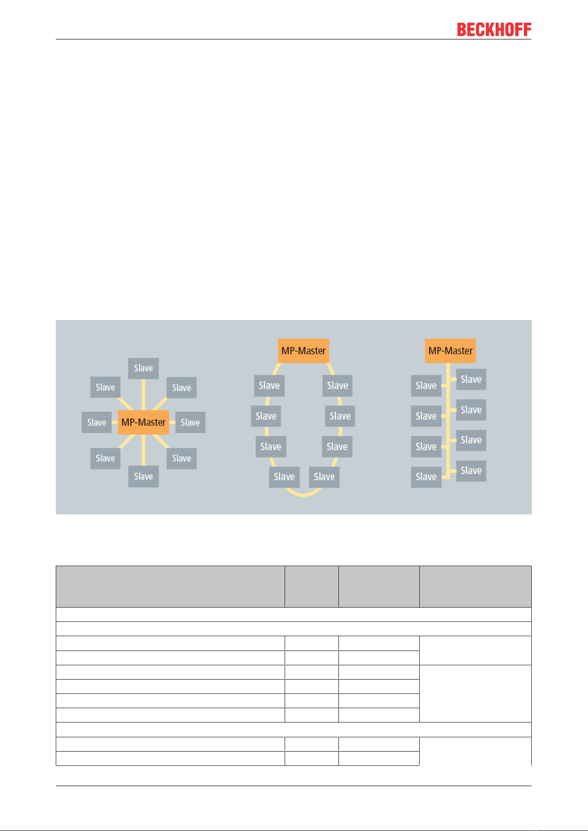
4 MP-Bus.....................................................................................................................................................10
4.1 Topology .........................................................................................................................................10
4.2 Actuator solutions for MP-Bus.........................................................................................................10
5 Integration into TwinCAT........................................................................................................................14
5.1 KL6771 - Linking to the TwinCAT System Manager .......................................................................14
5.2 Integration in TwinCAT (CX9020) ...................................................................................................16
5.3 Integration into TwinCAT (BC9191) ................................................................................................18
6 Programming...........................................................................................................................................22
6.1 General Information ........................................................................................................................24
6.2 Function blocks ...............................................................................................................................24
6.2.1 KL6771............................................................................................................................. 25
6.2.2 MP_Addressing................................................................................................................ 26
6.2.3 MP_CMV.......................................................................................................................... 28
6.2.4 MP_DamperLinearActuator.............................................................................................. 30
6.2.5 MP_EnergyValveV4_Configuration.................................................................................. 31
6.2.6 MP_EnergyValveV4_Process .......................................................................................... 34
6.2.7 MP_EPIV.......................................................................................................................... 36
6.2.8 MP_EPIV_R6 ...................................................................................................................38
6.2.9 MP_EPIV_R6_Parameter ................................................................................................39
6.2.10 MP_EV .............................................................................................................................41
6.2.11 MP_EV_Parameter ..........................................................................................................43
6.2.12 MP_MPX ..........................................................................................................................44
6.2.13 MP_PTH........................................................................................................................... 45
6.2.14 MP_RoomSensor............................................................................................................. 47
6.2.15 MP_RoomSensor_Parameter ..........................................................................................48
6.2.16 MP_Smoker .....................................................................................................................49
6.2.17 MP_TEM_Configuration................................................................................................... 51
6.2.18 MP_TEM_Process ...........................................................................................................52
6.2.19 MP_UST_3....................................................................................................................... 53
6.2.20 MP_VAV........................................................................................................................... 56
6.2.21 MP_VRU_Configuration................................................................................................... 58
6.2.22 MP_VRU_Process ...........................................................................................................59
6.2.23 MP_Window .....................................................................................................................61
6.2.24 MPL_DamperLinearActuator............................................................................................ 62
6.3 Functions.........................................................................................................................................63
6.3.1 NI1000_LuS_TO_INT : INT.............................................................................................. 63
6.3.2 NI1000_TO_INT : INT ...................................................................................................... 64

Table of contents
TX12004 Version: 1.1
6.3.3 NTC_TO_INT : INT .......................................................................................................... 64
6.3.4 PT1000_TO_INT : INT ..................................................................................................... 64
6.4 Data types .......................................................................................................................................65
6.4.1 Enums ..............................................................................................................................65
6.4.2 Structures......................................................................................................................... 72
6.5 Error codes......................................................................................................................................75
7 Appendix..................................................................................................................................................77
7.1 Examples ........................................................................................................................................77
7.2 Support and Service........................................................................................................................77

Foreword
TX1200 5Version: 1.1
1 Foreword
1.1 Notes on the documentation
This description is only intended for the use of trained specialists in control and automation engineering who
are familiar with applicable national standards.
It is essential that the documentation and the following notes and explanations are followed when installing
and commissioning the components.
It is the duty of the technical personnel to use the documentation published at the respective time of each
installation and commissioning.
The responsible staff must ensure that the application or use of the products described satisfy all the
requirements for safety, including all the relevant laws, regulations, guidelines and standards.
Disclaimer
The documentation has been prepared with care. The products described are, however, constantly under
development.
We reserve the right to revise and change the documentation at any time and without prior announcement.
No claims for the modification of products that have already been supplied may be made on the basis of the
data, diagrams and descriptions in this documentation.
Trademarks
Beckhoff®, TwinCAT®, TwinCAT/BSD®, TC/BSD®, EtherCAT®, EtherCAT G®, EtherCAT G10®, EtherCAT P®,
Safety over EtherCAT®, TwinSAFE®, XFC®, XTS® and XPlanar® are registered trademarks of and licensed by
Beckhoff Automation GmbH.
Other designations used in this publication may be trademarks whose use by third parties for their own
purposes could violate the rights of the owners.
Patent Pending
The EtherCAT Technology is covered, including but not limited to the following patent applications and
patents:
EP1590927, EP1789857, EP1456722, EP2137893, DE102015105702
with corresponding applications or registrations in various other countries.
EtherCAT® is a registered trademark and patented technology, licensed by Beckhoff Automation GmbH,
Germany
Copyright
© Beckhoff Automation GmbH & Co. KG, Germany.
The reproduction, distribution and utilization of this document as well as the communication of its contents to
others without express authorization are prohibited.
Offenders will be held liable for the payment of damages. All rights reserved in the event of the grant of a
patent, utility model or design.

Foreword
TX12006 Version: 1.1
1.2 Safety instructions
Safety regulations
Please note the following safety instructions and explanations!
Product-specific safety instructions can be found on following pages or in the areas mounting, wiring,
commissioning etc.
Exclusion of liability
All the components are supplied in particular hardware and software configurations appropriate for the
application. Modifications to hardware or software configurations other than those described in the
documentation are not permitted, and nullify the liability of Beckhoff Automation GmbH & Co. KG.
Personnel qualification
This description is only intended for trained specialists in control, automation and drive engineering who are
familiar with the applicable national standards.
Description of symbols
In this documentation the following symbols are used with an accompanying safety instruction or note. The
safety instructions must be read carefully and followed without fail!
DANGER
Serious risk of injury!
Failure to follow the safety instructions associated with this symbol directly endangers the life and health of
persons.
WARNING
Risk of injury!
Failure to follow the safety instructions associated with this symbol endangers the life and health of per-
sons.
CAUTION
Personal injuries!
Failure to follow the safety instructions associated with this symbol can lead to injuries to persons.
NOTE
Damage to the environment or devices
Failure to follow the instructions associated with this symbol can lead to damage to the environment or
equipment.
Tip or pointer
This symbol indicates information that contributes to better understanding.

Foreword
TX1200 7Version: 1.1
1.3 Notes on information security
The products of Beckhoff Automation GmbH & Co. KG (Beckhoff), insofar as they can be accessed online,
are equipped with security functions that support the secure operation of plants, systems, machines and
networks. Despite the security functions, the creation, implementation and constant updating of a holistic
security concept for the operation are necessary to protect the respective plant, system, machine and
networks against cyber threats. The products sold by Beckhoff are only part of the overall security concept.
The customer is responsible for preventing unauthorized access by third parties to its equipment, systems,
machines and networks. The latter should be connected to the corporate network or the Internet only if
appropriate protective measures have been set up.
In addition, the recommendations from Beckhoff regarding appropriate protective measures should be
observed. Further information regarding information security and industrial security can be found in our
https://www.beckhoff.com/secguide.
Beckhoff products and solutions undergo continuous further development. This also applies to security
functions. In light of this continuous further development, Beckhoff expressly recommends that the products
are kept up to date at all times and that updates are installed for the products once they have been made
available. Using outdated or unsupported product versions can increase the risk of cyber threats.
To stay informed about information security for Beckhoff products, subscribe to the RSS feed at https://
www.beckhoff.com/secinfo.

Target groups
TX1200 9Version: 1.1
3 Target groups
The user of this library requires basic knowledge of the following:
• TwinCAT PLC-Control
• TwinCAT System Manager
• PCs and networks
• Structure and properties of the Beckhoff Embedded PC and its Bus Terminal system
• Technology of MP-Bus devices
• Relevant safety regulations for building technical equipment
This software library is intended for building automation system partners of Beckhoff Automation GmbH &
Co. KG. The system partners operate in the field of building automation and are concerned with the
installation, commissioning, expansion, maintenance and service of measurement, control and regulating
systems for the technical equipment of buildings.

MP-Bus
TX120010 Version: 1.1
4 MP-Bus
MP-bus = multi-point bus
The MP-Bus (Multi-Point) is a simple sensor/actuator bus, which is used for certain technical systems of the
building automation system. The MP-Bus serves to control HVAC actuators for dampers, control valves and
volume flow controllers from the Belimo product range. Up to eight different devices from HVAC systems can
be connected to an MP-Bus master using 3-wire technology. Additionally, a sensor can be connected to
each of these eight devices; the sensor is addressed by the MP-Bus. An additional range of products with an
MP-Bus connection is the FLS window ventilation system by Belimo (see Belimo documentation for the
connection of the Belimo actuators).
The MP-Bus was developed by Belimo for connecting valves, throttle valves, air valves, fire dampers, and for
window ventilation systems.
4.1 Topology
There are no restrictions whatsoever with regard to the topological structure of MP-Bus strands: star, ring,
tree or mixed topologies are possible. The length of the entire bus strand depends on the selected cable
cross-section and the type as well as the number of connected drives! Documentation from the Belimo
Automation AG contains further information.
4.2 Actuator solutions for MP-Bus
Types ¹ Unit ready for
extended MP-
Bus® ²
Beckhoff function
block
General air solution
Rotary actuators
CM24-MPL-L 2 Nm • MPL_DamperLinearAc-
tuator
CM24-MPL-R 2 Nm •
LM24A-MP 5 Nm MP_DamperLinearActu-
ator
NM24A-MP 10 Nm
SM24A-MP 20 Nm
GM24A-MP 40 Nm
Rotary actuators with emergency control function
TF24-MFT 2 Nm MP_DamperLinearActu-
ator
LF24-MFT2 4 Nm

MP-Bus
TX1200 11Version: 1.1
Types ¹ Unit ready for
extended MP-
Bus® ²
Beckhoff function
block
NF24A-MP 10 Nm
SF24A-MP 20 Nm
EF24A-MP 30 Nm
GK24A-MP 40 Nm
Linear actuators
LH24A-MP... 60/100/200/300 150 Nm MP_DamperLinearActu-
ator
SH24A-MP... 100/200/300 450 Nm
Linear actuators with emergency control function
LHK24A-MP100 150 Nm MP_DamperLinearActu-
ator
SHK24A-MP100 450 Nm
Rotary actuators
LU24A-MP 3 Nm MP_DamperLinearActu-
ator
Fast running rotary actuators
NMC24A-MP 10 Nm MP_DamperLinearActu-
ator
SMC24A-MP 20 Nm
Rotary actuators for special applications
NM24P-MP 10 Nm MP_DamperLinearActu-
ator
SM24P-MP 20 Nm
GM24G-MP-T 40 Nm
Rotary actuators with emergency control function for special applications
NF24G-MP-L 10 Nm MP_DamperLinearActu-
ator
SF24G-MP-L 20 Nm
GK24G-MP 40 Nm
Water solutions
Actuators for characterized control valves / open-close ball valves
CQ24A-MPL 1 Nm • MPL_DamperLinearAc-
tuator
LR24A-MP 5 Nm MP_DamperLinearActu-
ator
NR24A-MP 10 Nm
SR24A-MP 20 Nm
Actuators with emergency control function for characterized control valves / open-close ball valves
TRF24-MFT 2 Nm MP_DamperLinearActu-
ator
LRF24-MP 4 Nm
NRF24A-MP 10 Nm
Actuators for globe valves
LV24A-MP-TPC 500 N MP_DamperLinearActu-
ator
NV24A-MP-TPC 1000 N
SV24A-MP-TPC 1500 N
EV24A-MP-TPC 2500 N
Actuators with emergency control function for globe valves
NVK24A-MP-TPC 1000 N MP_DamperLinearActu-
ator
AVK24A-MP-TPC 2000 N
Fast running actuators for globe valves
LVC24A-MP-TPC 500 N MP_DamperLinearActu-
ator
NVC24A-MP-TPC 1000 N
SVC24A-MP-TPC 1500 N

MP-Bus
TX120012 Version: 1.1
Types ¹ Unit ready for
extended MP-
Bus® ²
Beckhoff function
block
Fast running actuators with emergency control function for globe valves
NVKC24A-MP-TPC 1000 N MP_DamperLinearActu-
ator
Actuators for butterfly valves
SR24A-MP-5 20 Nm MP_DamperLinearActu-
ator
GR24A-MP-5/7 40 Nm
DR24A-MP-...5/7 90 Nm
PRCA-BAC-S2-T 160 Nm
PRKCA-BAC-S2-T 160 Nm
SY2-24-MP-T 90 Nm
SY2-230-MP-T 90 Nm
SY3-24-MP-T 150 Nm
SY3-230-MP-T 150 Nm
SY4-24-MP-T 400 Nm
SY4-230-MP-T 400 Nm
SY5-24-MP-T 500 Nm
Safety solutions
"BF-TopLine" actuators for fire dampers
BKN230-24MP for connection of BF(G)24TL-T-ST 11 / 18 Nm MP_Smoker
Standard actuator for fire dampers
BKN230-24-C-MP for connection of BF..24-..ST 4 / 9 / 11 /
18 Nm
MP_Smoker
Room and system solutions
VAV compact rotary actuators
LMV-D3-MP 5 Nm MP_VAV
NMV-D3-MP 10 Nm
SMV-D3-MP 20 Nm
VAV compact linear actuators
LHV-D3-MP 150 N MP_VAV
VAV Universal
VRP-M MP_VAV
VRU-D3-BAC MP_VRU_Process
MP_VRU_Configuration
VRU-M1-BAC
VRU-M1R-BAC
VAV control system for controlled living area ventilation systems
CMV-100-MP DN 100 • MP_CMV
CMV-125-MP DN 125 •
CMV-150-MP DN 150 •
CMV-160-MP DN 160 •
HVAC performance devices
EPIV
EP..R-R6+BAC DN 15-20 • MP_EPIV_R6
MP_EPIV_R6_Parame-
ter
EP..R+MP DN 15-20 MP_EPIV
P..W..E-MP DN 65-150
Belimo Energy Valve™

MP-Bus
TX1200 13Version: 1.1
Types ¹ Unit ready for
extended MP-
Bus® ²
Beckhoff function
block
EV..R+BAC DN 15-50 • MP_EV
MP_EV_Parameter
P..W..EV-BAC DN 65-150 •
Belimo Energy Valve™ V4
EV..R2+.. DN 15-50 • MP_Energy-
ValveV4_Process
MP_Energy-
ValveV4_Configuration
Thermal Energy Meter
22PE- .. • MP_TEM_Process
MP_TEM_Configuration
22PEM-.. •
Sensors
Room sensors in the comfort zone
22RT-19-1 (temp.) • MP_RoomSensor
MP_RoomSensor_Pa-
rameter
22RTH-19-1 (temp., rh) •
22RTM-19-1 (temp., CO₂, rh) •
MS24A-R02-MPX (Temp., CO₂) • MP_MPX
MS24A-R08-MPX (Temp., VOC, CO₂, rH) •
¹ The currently available product range can be found online at www.belimo.eu.
² The marked devices support the extended address range. Up to 16 MP devices (addressed MP1 ... MP16)
can be connected to a data line. If unmarked devices are connected to the same data line, the common
address range should be limited to 8 MP devices.

Integration into TwinCAT
TX120014 Version: 1.1
5 Integration into TwinCAT
5.1 KL6771 - Linking to the TwinCAT System Manager
How do I link the KL6771 to the System Manager?
1. Select All Types and Continuous
2. Click the mouse on the first variable in the KL6771 Parameter Status. Then press the [SHIFT] key, and
hold it down. Take the mouse pointer to the last variable in the KL6771 Input Data 10, and again click
the left mouse button. Now release the [SHIFT] key again.
ðAll the terminal's data should now be highlighted (see Figure).

Integration into TwinCAT
TX1200 15Version: 1.1
3. Then press the OK button.
4. You can now check the link. To do this, go to the KL6771 and open it. All the terminal's data should now
be marked by a small arrow (see Figure).
ðIf that is the case, then proceed in exactly the same way with the outputs.

Integration into TwinCAT
TX120016 Version: 1.1
5.2 Integration in TwinCAT (CX9020)
This example describes how a simple PLC program for MP-Bus can be written in TwinCAT and how it is
linked with the hardware. The task is to control an individual flap drive and change it with a button.
Unpacking the example files https://infosys.beckhoff.com/content/1033/tcplclibmpbus/Resources/
zip/12063685643.zip
Hardware
Setting up the components
The following hardware is required:
• 1x Bus Terminal Controller CX9020
• 1x digital 2-channel input terminal KL1002 (for the Open and Close functions)
• 1x MP-Bus master terminal KL6771
• 1x end terminal KL9010
Set up the hardware and the MP-Bus components as described in the associated documentation.
This example assumes that the address of the flap drive is known.
Software
Creation of the PLC program
Create a new PLC project for PC-based systems (ARM) and add the TcMPBus.lib library.
Next, generate the following global variables:
VAR_GLOBAL
bOpenAT%I*:BOOL;
bCloseAT%I*:BOOL;
arrKL6771_INAT%I*:ARRAY[0..11]OFBYTE;
arrKL6771_OUTAT%Q*:ARRAY[0..11]OFBYTE;
stDataKL6771:DataKL6771;
END_VAR
bOpen: input variable for the Open button.
bClose: input variable for the Close button.
arrKL6771_IN: input variable for the MP-Bus terminal.
arrKL6771_OUT: output variable for the MP-Bus terminal.
stDataKL6771: required for communication with MP-Bus (see DataKL6771 [}72]).
All function blocks with MP-Bus must be called in the same task.
Therefore, create a MAIN program (CFC) in which the KL6771() [}25] and MP_DamperLinearActuator()
[}30] function blocks are called. Make sure to link the communication block with arrKL6771_IN,
arrKL6771_OUT and stDataKL6771.

Integration into TwinCAT
TX1200 17Version: 1.1
The input SetPoint is set depending on the selected function. Link the global variables bOpen and bClose
with an auxiliary variable.
Go to the task configuration and give the task a lower interval time. More detailed information can be found
in the KL6771() [}25] function block description.
Load the project to the CX as the boot project and save it.
Configuration in the System Manager
Create a new TwinCAT System Manager project, select the CX as the target system, and search for the
associated hardware.
Add the PLC program created above under PLC configuration.

Integration into TwinCAT
TX120018 Version: 1.1
Now link the global variables of the PLC program with the Bus Terminal inputs and outputs, create the
allocations, and activate the configuration. Then start the device in run mode.
Your CX is now ready for use.
After pressing the button the flap drive can be moved. The current position is stored in variable wActValue.
5.3 Integration into TwinCAT (BC9191)
This example describes how a simple PLC program for MP-Bus can be written in TwinCAT and how it is
linked with the hardware. The task is to control an individual flap drive and change it with a button.
Unpacking the example files https://infosys.beckhoff.com/content/1033/tcplclibmpbus/Resources/
zip/12063687051.zip
Hardware
Setting up the components
The following hardware is required:
• 1x Bus Terminal Controller BC9191
• 1x potential feed terminal 24V DC
• 1x digital 2-channel input terminal KL1002 (for the Open and Close functions)
• 1x MP-Bus master terminal KL6771
• 1x end terminal KL9010
Set up the hardware and the MP-Bus components as described in the associated documentation.
This example assumes that the address of the flap drive is known.
Software
Creation of the PLC program
Create a new PLC project for BC-based systems (BCxx50 via AMS) and add the libraries TcMPBus.lbx and
TcSystemBCxx50.lbx. Then navigate to Project → Options... → Build and select Treat LREAL as REAL.

Integration into TwinCAT
TX1200 19Version: 1.1
Next, generate the following global variables:
VAR_GLOBAL
bOpenAT%I*:BOOL;
bCloseAT%I*:BOOL;
arrKL6771_INAT%I*:ARRAY[0..11]OFBYTE;
arrKL6771_OUTAT%Q*:ARRAY[0..11]OFBYTE;
stDataKL6771:DataKL6771;
END_VAR
bOpen: input variable for the Open button.
bClose: input variable for the Close button.
arrKL6771_IN: input variable for the MP-Bus terminal.
arrKL6771_OUT: output variable for the MP-Bus terminal.
stDataKL6771: required for communication with MP-Bus (see DataKL6771 [}72]).
All function blocks with MP-Bus must be executed in one task.
Therefore, create a MAIN program (CFC) in which the KL6771() [}25] and MP_DamperLinearActuator()
[}30] function blocks are called. Make sure to link the communication block with arrKL6771_IN,
arrKL6771_OUT and stDataKL6771.
The input SetPoint is set depending on the selected function. Link the global variables bOpen and bClose
with an auxiliary variable.

Integration into TwinCAT
TX120020 Version: 1.1
Go to the task configuration and give the task a lower interval time. More detailed information can be found
in the KL6771() [}25] function block description.
Now load the project as a boot project to the BC and save it.
Configuration in the System Manager
Create a new TwinCAT System Manager project, select the BC as the target system, and search for the
associated hardware.
Add the PLC program created above under PLC configuration.
Now link the global variables of the PLC program with the Bus Terminal inputs and outputs, create the
allocations, and activate the configuration. Then start the device in run mode.
Table of contents
Other Beckhoff Motherboard manuals

Beckhoff
Beckhoff EtherCAT EL9800 User manual

Beckhoff
Beckhoff CB1051 User manual

Beckhoff
Beckhoff CB1052 User manual

Beckhoff
Beckhoff CB4055 User manual

Beckhoff
Beckhoff CB1064 Series User manual

Beckhoff
Beckhoff CB3064 Series User manual

Beckhoff
Beckhoff CB1050 User manual

Beckhoff
Beckhoff CB4055 User manual

Beckhoff
Beckhoff CB6464 User manual

Beckhoff
Beckhoff CB3055 User manual