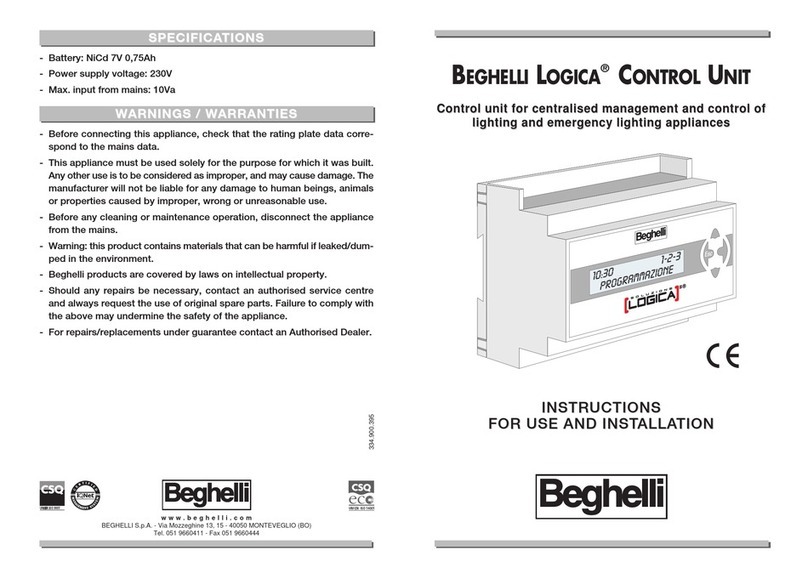
Beghelli LOGICA SUPERVISOR 12131C User manual

LOGICA SUPERVISOR CONTROL UNIT
code 12131C
Su ervisor Control Unit for the centralised management and
control of normal and emergency lighting systems
INSTALLATION
AND OPERATING INSTRUCTIONS

2
TABLE OF CONTENTS
•WHAT IS THE SUPER ISOR CONTROL UNIT BY BEGHELLI pag. 3
•FUNCTIONS pag. 3
System monitoring pag. 3
System Control pag. 3
Keeping a Logbook pag. 3
•INSTALLATION pag. 4
RS 485 line use and termination pag. 6
Operations Required to Render the Supervisor Control Unit Operational pag. 6
eyboard and display functions pag. 6
Date and Time Settings pag. 7
Searching for Logica Control Units (New Configuration) pag. 8
Scheduling Functional and Autonomy Tests pag. 9
•GROUPS pag. 10
•MENU pag. 11
Luminaires Menu pag. 11
Maintenance Menu pag. 12
Manual Test pag. 12
Emergency pag. 13
Error Status pag. 13
Management Test pag. 14
Control Unit Management pag. 14
Date & Time Changes pag. 14
Control Unit Code pag. 14
C Ups pag. 14
Ups presence pag. 14
Save/Ups/Mod. pag. 14
Print/Save pag. 15
Language pag. 15
Ethernet Network pag. 15
NEA Control Unit YES/NO pag. 15
Out. Err. On/off pag. 16
Out.Test/Errors pag. 16
St. Err. open/cl. pag. 16
Password on/off pag. 16
Password change pag. 16
Configuration pag. 16
Remote Configuration pag. 17
Remote Locking - Remote Unlocking pag. 17
Software Upgrade pag. 17
Status Menu pag. 17
•TECHNICAL CHARACTERISTICS pag. 18
•WARNINGS - WARRANTY pag. 18

3
The Supervisor Control Unit by Beghelli (code 12131C) is a device used for the centralised con-
trol of normal and emergency lighting systems. It controls and supervises up to 31 Logica
Control Units by Beghelli via a RS485 bus (control unit code 12100C), and each control unit, in
its turn, can handle up to 128 normal and emergency luminaires on a DALI bus, according to
IEC60929.
It can also be used with centralised battery lighting/emergency systems, interfacing with the ups
units via bus RS232_B and with NEA systems, up to 63 NEALOG (code 16318) via bus RS485;
each control unit, in its turn, can handle up to 64 NEA luminaires.
The Control Unit consists of:
- eyboard + display for user operations;
- RS485 interface for connections to Logica Control Units by Beghelli (code 12100);
- RS485 interface for Supervisor Unit remote control via PC or modem connection;
- RS232 interface that can be connected to the Logica DIN RS232 serial printer by Beghelli (code
12099);
- ethernet interface to enable the use of the device with a LAN network;
- USB interface for software updates.
The Supervisor Control Unit performs the following tasks:
SYSTEM MONITORING
The Supervisor Control Unit keeps the connected Logica (or Nealog) Control Units under perma-
nent supervision, detects and reports any Control Unit/ luminaire malfunction.
SYSTEM CONTROL
The Supervisor Control Unit allows the user to adjust the brightness of the luminaires, perform
Functional and Autonomy tests on the system emergency luminaires, set Test times and fre-
quency. etc...
KEEPING A LOGBOOK
The Supervisor Control Unit tracks test outcomes and, in general, any relevant operation in the
system.
If a printer is available (code 12099) this information can be regularly printed on paper; if the-
re is a USB flash drive connected, the information can be saved in the form of files and if a PC
connection is available, this information can be sent and saved on a computer.
The Supervisor Control Unit can store information related to a period of about two years; it will
then start deleting older logs to make space for new data (the stated time refers to a system of
4000 luminaires, with Functional Tests performed every 15 days and Autonomy tests performed
every 6 months; smaller systems with different Test frequencies will have a higher/lower log-
book duration).
WHAT IS THE SUPER ISOR CONTROL UNIT BY BEGHELLI
FUNCTIONS

4
INSTALLATION
Use the layout below for reference to connect the Supervisor Control Unit to Logica Control Units
(RS485 bus) and, if applicable, to the printer (RS232 bus)
The connection to the system, via the LogicaVisual software, can be made via RS485_A and
ETHERNET (starting from firmware version 1.20)
Logica DALI control unit
Logica DALI control unit
Logica DALI control unit
Logica
Logica
Logica
BS100
up to 128
up to 128
up to 128
BS100
BS100
LOGICA supervisor control unit
Esc
ok
Esc
ok
Esc
ok
Esc
ok
Personal
Computer
Printer
Logica
Other interfaces:
USB
ETHERNET
RS232
Interface GSM

5
INPUT: for the connection of buttons, switches, outputs of other technological systems (e.g. anti-
theft). Dry contact.
OUTPUT: open collector output. Vmax 24V; Imax 50mA
k
O
c
s
E
^
^
MAINS RADIO
MAINS 230V
(YELLOW)
(BLUE)
(GREY)
(BLACK)
MAINS 230V
LINK T O :
- ETHERNET INTERFACE
- USB INTERFACE
- RS23 2 I N TERFA C E
DIN PR I N TER
cod. 1 2099
CONF I G URE TH E PRIN T E R
IN RS2 3 2 M ODE
BY SOL D E RING THE J U M PERS
LOGICA SUPERVISOR CONTROL UNIT
cod. 12131C
LOGI C A C ONTROL U N I T
cod. 1 2 1 00C
MAX 31 C O N TROL UN I T S
DALISWIT C HES
A D
GND
4 3 2 1
OkEsc

6
OPERATIONS REQUIRED TO RENDER THE SUPER ISOR CONTROL UNIT OPERA-
TIONAL
KEYBOARD AND DISPLAY FUNCTIONS
Pressing the keys enables the user to move through the screens, to display information and select
the operation mode.
The three main menus are LIGHTS, MAINTENANCE AND STATUS;
- to move from one menu to another, use the “DOWN” Cand “UP” Dkeys
- to enter the menu and access additional functions, use the “O ” B keys
- to return to a higher menu level, use the “ESC” A keys
- to move from the first to the last level of each menu (circular menus) press D(eg: in MANUAL
TEST press Dto go to SOFTWARE UPGRADE).
Other key functions:
- use the "DOWN" Cand "UP" Dkeys to change a value (for example, in the date and
time settings menu, with the hour indication "08" flashing, press Dto increase the
value to "09", press Cto decrease the value to "07")
- use key "O " Bkey to confirm the entered value (by reference to the example given at
the previous point, if, after changing the hour value to "07", you press B, this value will
be stored on the Control Unit) .
RS 485 LINE USE AND TERMINATION
The Control Unit is equipped with 2 separate RS 485 lines (RS485_A and RS485_B); impedance
adjustment possible on both lines by adding 2 2.54 pitch jumpers.
Impedance adjustment is needed when the Control Unit is the "terminal" part of BUS 485 (the
beginning or the end of the path).
To adjust the RS485_A line, insert the Jumpers in connectors J22 and J23. To adjust the
RS485_B line, insert the Jumpers in connectors J20 and J21.
CO
COM UX
-UX
+
RETE RADIO
PN
RS485_A
OUT3
R
+-
5V IN
Reset
BOOT
00 - SD
01 - eMMC
10 - NAND
Term. 485
J20
J21
J23
J22
MAINS

DATE AND TIME SETTINGS
7
At the first start up, the system displays the LIGHTS
menu: SAB 00:00:01
LIGHTS
Press the keys shown on the right in sequence to go
to the menu for time setting:
CSAB 00:00:01
MAINTENANCE
BM inten nce
MANUAL TEST
DM inten nce
SOFTWARE UPGRADE
D X 5 M inten nce
CTRL UNIT MGT.
BCtrl Unit Mgt.
CHANGE DATE-TIME
Press Bagain to enter the menu that shows the date
currently set on the Control unit appears and the
day indication will be flashing (“01”). Press Duntil
the desired day is displayed, then press Bto confirm.
Now the month indication will start flashing (to change
it, follow the same procedure as for setting the day).
Ch nge d te-time
01-01-2019 00:00
Apply the same method to set the year, hour and minu-
tes. Press Bto confirm the value set for minutes;
now, the display will show "COMMAND EXECUTED".
15-06-2019 15:45
COMMAND EXECUTED

8
SEARCHING FOR LOGICA CONTROL UNITS (NEW CONFIGURATION)
N.B.: before proceeding, make sure that a different address is set for each Logica Control Unit
installed and wired to the Supervisor Control Unit; to set an address for a Logica Control Unit,
refer to the “Logica Control Unit by Beghelli” manual.
N.B.: also check that the system configuration command has been executed on all Logica
Control Units installed and wired to the Supervisor Control Unit (see the “Logica Control Unit by
Beghelli” manual).
After completing these checks, launch the search procedure, which will make the Supervisor
Control Unit search for Logica Control Units connected to it.
N.B.: if the number of Logica Control Units found does not match the number of Control Units con-
nected to the Supervisor Control Unit, check the system wiring.
The same procedure applies for NEALOG devices (code 16318).
In this case, before initiating the configuration phase, search on the Supervisor Control Unit for the
Nea devices, proceeding as follows:
Maintenance B Ctrl Unit Mgt B NEA Ctrl Unit YES/NO B YES B
N.B.: Where applicable, the menu pages may also contain indications related to the NEA system.
Assuming you start from the LIGHTS menu: press the
keys shown on the right in sequence to go to the new
configuration search menu.
SAB 00:00:01
LIGHTS
CSAB 00:00:01
MAINTENANCE
BM inten nce
MANUAL TEST
DM inten nce
SOFTWARE UPGRADE
D X 4 M inten nce
CONFIGURATION
BConfigur tion NEW

9
Press Bto launch the search for Control Units. During
the search, the two numbers shown on screen, divided
by a
dash, mean:
- on the left: total number of Control Units detected up
to that moment
- on the right: address of the Logica Control Unit under-
going checks to see if it is connected to the system.
Ctrl Unit Config.
in progress
000-000
At the end of the search, the number of Logica Control
Units detected will be shown on screen.
Tot l
02 CONTROL UNITS
N.B.: if the number of Logica Control Units found does not match the number of Control Units con-
nected to the Supervisor Control Unit, check the system wiring.
The same procedure applies when searching for NEALOG devices.
SCHEDULING FUNCTIONAL AND AUTONOMY TESTS
The Functional and Autonomy Tests are meant to check the emergency luminaires. Functional
Tests consist in turning on the luminaire for about 30 seconds and checking the luminaire light
source and battery efficiency; Autonomy Tests consist in turning on the luminaire for extended
periods of time and checking if the battery is still working. If the Tests reveal that the luminai-
re is faulty, this information will be transmitted from the luminaire to the Logica Control Unit and
then to the Supervisor Control Unit: an error message will be displayed on the screen of the
Supervisor Control Unit and the error will be recorded in the Logbook.
The Supervisor Control Unit allows you to set the date and time of the next tests either indivi-
dually, for each Logica Control Unit, or globally, for all Logica Control Units in the system. After
setting the date and time of the next Functional and Autonomy Tests, all subsequent tests will
be performed at a regular interval, which can also be set in the menu of the Control Unit.
For a correct operation of the system, the following must be set:
- Date and time of the next Functional Test;
- Date and time of the next Autonomy Test;
- Time interval between repeated Functional Tests;
- Time interval between repeated Autonomy Tests.

10
Luminaires connected to each Logica Control Unit by Beghelli can be divided into groups to
perform separate operations on system sections. Each luminaire can belong to a group, multi-
ple groups or no group. The total number of groups available is 16.
Assigning a luminaire to a group is an operation that needs to be performed on the Logica Control
Unit to which that luminaire is connected; for this, refer to the “Logica Control Unit by Beghelli”
manual.
The Supervisor Control Unit has the same Group concept as the Logica Control Units: any ope-
ration performed from the Supervisor Control Unit on a group, will affect the corresponding group
of each Logica Control Unit by Beghelli in the system; if a command is sent to group '1' from the
Supervisor Control Unit by Beghelli, that command will affect all luminaires belonging to group
'1' of each Logica Control Unit by Beghelli.
GROUPS
Press Bto show the date of the Next Functional Test
stored on the Control Unit.
To set the time of the test, proceed as shown in section
"Date and Time Settings".
Next Func Test
31-12-2099 00:00
Assuming you start from the LIGHTS menu: press the
keys shown on the right in sequence to go to the date-
time settings menu for the next Functional Test.
("x 3" means you have to press the key three times)
SAB 00:00:01
LIGHTS
CSAB 00:00:01
MAINTENANCE
BM inten nce
MANUAL TEST
C x3 M inten nce
MANAGEMENT TEST
BM n gement Test
ALL
BAll NEXT FUNC TEST
The example below shows how to set the date and time of the next Functional Test.

11
The system is organised in menus that allow you to access varied features of the system: turn
luminaires on and off, perform Functional and Autonomy Tests, review information on mal-
functions, etc...
To understand how to navigate among screens using the keys, see section “ eyboard and
Display Functions”.
Most of the operations that can be performed can be applied to the entire system or to a portion of it,
as indicated in the following table:
The system features 3 main menus: LIGHTS, MAINTENANCE AND STATUS.
LIGHTS MENU
How to use this menu to modify the brightness of the bulbs:
To perform an operation on: go to the menu::
all luminaires in the system ALL
all luminaires of Logica Control Unit XXX CTRL UNIT XXX
all luminaires in Group yy GROUP YY
go to the menu:
for the maximum level of brightness ON (MAX)
to turn them off TO TURN THEM OFF
for an intermediate brightness level XX DIMMER STEP XX
MENU

12
MAINTENANCE MENU
MANUAL TEST
The Functional and Autonomy Tests are meant to check the emergency luminaires. Functional
Tests consist in turning on the luminaire for about 30 seconds and checking the luminaire tube
and battery efficiency; Autonomy Tests consist in turning on the luminaire for extended periods
of time and checking if the battery is still working.
Normally, Functional and Autonomy Tests are run automatically at regular intervals according
to the schedule set by the user (see "Scheduling Functional and Autonomy Tests") but it is also
possible to perform Functional or Autonomy Tests directly from the keyboard: Manual Test.
The manual tests are interrupted after the related time set has lapsed or by sending a stop test
command.
Manual Tests will not change the time intervals and durations set for the automatic Tests.
Use the MANUAL TEST menu to perform the operations described in the following table:
To: go to the menu:
run a Functional Test FUNCTION
run an unlimited time test that will stop when the
battery is empty ALWAYS ON
run a set time test 00h 04m 15s
...
06h 01m 15s
stop any test STOP TEST

13
EMERGENCY
N.B.: commands in the EMERGENCY menu will only affect luminaires that are not powered
from the mains, i.e. they are lit in a state of emergency.
When power from the mains to a luminaire is cut off, the luminaire will turn on and run on bat-
tery supply. As long as its battery still has energy stored, any of the following commands can
be sent to the luminaire:
- Disable the state of emergency: the luminaire turns off; it can be turned back on by enabling
the state of emergency.
- Enable the state of emergency: the luminaire turns on
- Turn off: the luminaire is turned off permanently; it cannot be turned back on unless the lumi-
naire itself detects mains power. This feature can be useful to preserve the bulbs batteries
when, for instance, it is necessary to remove the power supply to the system for a long
period.
To: go to the menu:
disable the state of emergency EMERG. UNENABLED
enable the state of emergency EMERG.ENABLED
permanently turn off the luminaire OFF
ERROR STATUS
This menu allows you to review and clear luminaire faults.
If there is no error on any of the Logica Control Units by Beghelli connected to the Supervisor
Control Unit by Beghelli, this menu will show:
Error St tus
NO ERROR
If there is an error on at least one luminaire, the following operations will be possible:
To: go to the menu:
display the malfunctions associated with the
luminaires belonging to Control Unit XXX CTRL UNIT XXX
clear the malfunctions on a selected luminaire
belonging to Control Unit XXX
CONTROL UNIT XXX
LOGICA ZZZZZZ
clear the error signals for all the luminaires in the
system ALL
clear the error signals for all the luminaires in
Group YY GROUP YY

14
CONTROL UNIT MANAGEMENT
Date & Time Changes
To set the date and time on the Supervisor Control Unit, see section "Date and Time Settings".
The Supervisor Control Unit synchronises the timetable of all connected Logica Control Units.
Control Unit Code
The user can set the code of the Supervisor Control Unit: a number from 0 to 32.
C Ups
This menu can be used to control a particular type of ups unit.
Ups presence
If you enabled the Ups groups from the previous menu, in this menu you can check their pre-
sence.
Save/Ups/Mod.
From this menu you can select what to connect to RS232_A:PRINTER/USB, other types of ups
units or remote host with Modbus communication.
TEST MANAGEMENT
This menu allows you to set, either individually for each Control Unit, or globally, for all Control
Units:
- Date and time of the next Functional Test;
- Date and time of the next Autonomy Test;
- Time interval between repeated Functional Tests
- Time interval between repeated Autonomy Tests
For test date, time and test scheduling, see section "Scheduling Functional and Autonomy
Tests".
Based on their unique identifying addresses, LOGICA luminaires are divided into EVEN-numbe-
red and ODD-numbered luminaires. Using the EVEN-ODD TEST menu, you can decide whether
to perform an autonomy test on all luminaires simultaneously or first on the odd-numbered lumi-
naires, then, 7 days later, on the even-numbered luminaires.
To: go to the menu:
set a single simultaneous Test for all luminai-
res SIMULTANEOUS
set a Test for even-numbered luminaires 7 days
after the test on odd-numbered luminaires DELAY 7 DAYS

15
Print/Save
N.B.: printing will be available if the Supervisor Control Unit is connected to a Logica Din RS232
serial printer by Beghelli (code 12099). As an alternative, the data can be stored in files on a USB
flash drive that can be connected to port USB1. This menu is available if the PRINTER/USB option
has been selected in the previous menu.
The following data can be printed/saved:
-Configuration: list of installed luminaires and their characteristics (model, even/odd-num-
bered, 1h/3h autonomy, etc.).
-Scheduling: timetables for Functional and Autonomy Tests, time intervals for testing, stag-
gered testing on odd- and even-numbered luminaires.
-Errors: for each faulty luminaire, a warning is given that specifies the type of fault (e.g. 8W
tube error, battery charge error, etc.).
-Report: for this menu, you must enter a start date and an end date for the report. The prin-
tout will list significant actions that occurred over the set time frame involving the Logica Control
Units by Beghelli installed in the system. The printout will report the start time and the end
time of the Functional or Autonomy Tests performed, be they manual or automatic tests, and
a list of faulty luminaires.
The following controls are available in the PRINT/SAVE menu:
Language
The user can set a different display language. Available languages: ITALIAN, GERMAN, ENGLI-
SH, FRENCH and POLISH.
Ethernet Network
From this menu, the user can set the IP ADDRESS, the NETMAS , the DEFAULT GATEWAY, the
DNS, the PORT, the DHCP and view the MAC ADDRESS.
NEA Control Unit YES/NO
From this menu, the user can enable the control of the NEA system.
To: go to the menu:
print/save the Configuration CONFIGURATION
print/save the Programmation PROGRAMMATION
print/save Errors ERRORS
print/save Reports REPORT

16
Out. Err. On/off
The user can enable or disable the use of an auxiliary output, OUT2, to signal errors in the system
or Tests in progress.
Out.Test/Errors
The auxiliary output is activated during Tests or when there are errors in the system.
St. Err. open/cl.
You can set how the auxiliary output, OUT2, operates. Once enabled, it can be set in normally
open or normally closed mode: "normally open" means the output will remain open if there is
no error or Test in progress; "normally closed" means the output will remain closed if there is
no error or Test in progress.
Password on/off
You can enable/disable the password-protected use of the Supervisor Control Unit. Possible values
are ON and OFF.
Password change
You can set a password of 6 characters. Once the password is entered, you will be prompted
to enter it again for confirmation.
CONFIGURATION
This menu is usually used when installing the system or replacing the Supervisor Control Unit.
Using this menu, the Supervisor Control Unit detects how many and what Logica Control Units are
connected to it.
See section “Searching for Logica Control Units (New Configuration)” for more details on how to
activate this search.
kOcsE
^
^
POWER SUPPLY
RELAY

17
REMOTE CONFIGURATION
Using this menu, the Supervisor Control Unit can request each connected Logica Control Unit sepa-
rately or all Logica Control Units in the system to search for luminaires connected to it/them.
Basically, you can use the Supervisor Control Unit to send a command equivalent to "SYSTEM CON-
FIGURATION", which is available on the Logica Control Units.
The Logica Control Unit by Beghelli to which such a command is sent will perform a search for
connected luminaires; the operation generally takes less than a minute. Within another minute
or so, the Logica Control Unit will send to the Supervisor Control Unit all the information related
to detected luminaires.
REMOTE LOCKING - REMOTE UNLOCKING
These menus allow you to lock or unlock the keyboard of each connected Logica Control Unit.
eyboard locking prevents unauthorised persons from tampering with the Control Units: this
protection is achieved by prompting for a password when a key is pressed on the keyboard. After
typing in the password, the user will be able to freely operate the Control Unit for a few minutes
and then he/she will have to enter the password again. For more details, see the “Logica Control
Unit by Beghelli” manual.
SOFTWARE UPGRADE
This menu allows you to update the software of the Supervisor Control Unit. You need to have a
USB stick with properly configured directories and contents: new software version, configuration
files, logbook and possibly new images. Contact Technical Support to proceed.
STATUS MENU
The STATUS menu provides the following information:
Info Screen
no. of Logica Control Units by Beghelli con-
nected to the Supervisor Control Unit 03 LOGICA CONTROL UNIT
total no. of luminaires in the system TOT. LUMINAIRES 0321
how many Logica Control Units by Beghelli
have signalled at least one error 01 ERR: CTRL UNITS
how many luminaires have errors 0001 LOGICA CONTROL UNIT
software version of the Supervisor Control Unit
by Beghelli SW VER. 1.0

18
Code 21131C
- Power supply voltage: 230V~50Hz
- Max. input power: 12VA
- Degree of protection IP20
- Insulation class II (double insulation ensured by installation inside protected cabinets that can
be accessed with the use of a special tool, only by authorised service staff, for installation
and maintenance purposes)
- Operating ambient air temperature: 0°C +50°C
- Housing: plastic case on 9-module DIN rail
- Dimensions: 160 x 90 x 75 mm
TECHNICAL CHARACTERISTICS
- Before connecting the device, make sure the data on the rating plate match the specifications of
the mains.
- This device must be used according to its intended use. Any other use shall be deemed improper
and, therefore, dangerous. The manufacturer shall not be held liable for any injury or damage
caused to persons, animals or property as a result of improper, incorrect or unreasonable use.
- Before any cleaning or maintenance operations, disconnect the device from the mains.
- Warning: this product contains materials that may be harmful if disposed in the environment.
- The device must not be disposed of as municipal waste. It must be subjected to separate col-
lection to avoid polluting the environment. In compliance with Directive 2002/96 and imple-
menting national laws on end-of-life product disposal, a failure to comply with the above is
sanctioned by law.
- For any repairs, contact an authorised technical service centre and ask them to use original spa-
re parts. A failure to comply with the above may compromise the safety of the device.
- For details on interventions under warranty, please contact us at 800 626626 (toll-free) or contact
your Authorized Reseller.
WARNINGS - WARRANTY

19

www.beghelli.com
BEGHELLI S.p.A. - Via Mozzeghine 13/15 - località Monteveglio 40053 Valsamoggia (BO) - ITALY
Phone +39 051 9660411 - Fax +39 051 9660444
334.902.274 B
Table of contents
Other Beghelli Control Unit manuals

