Ziton ZP3-ECU User manual

ZP3-ECU Extinguishing
Control Unit Maintenance
Manual
P/N 503-0800ZE-M-04 • ISS 31JUL23

Copyright
©
2023 Carrier. All rights reserved.
Trademarks and
patents
The
ZP3-ECU name and logo are trademarks of Carrier.
Other trade names used in this document may be trademarks or
registered trademarks of the manufacturers or vendors of the
respective products.
Manufacturer
Carrier Manufacturing Poland Spółka Z o.o.
Ul. Kolejowa 24. 39
-100 Ropczyce, Poland.
Authorized EU manufacturing representative:
Carrier Fire & Security B.V.,
Kelvinstraat 7, 6003 DH Weert,
Netherlands.
Revision
04
Conformity
2014/30/EU (EMC Directive). Hereby,
Carrier declares that this
device is in compliance with the essential requirements and other
relevant provisions of Directive 2014/30/EU.
2012/19/EU (WEEE Directive): Products marked with this symbol
cannot be disposed of as unsorted municipal waste in the European
Union. For proper recycling, return this product to your local supplier
upon the purchase of equivalent new equipment, or dispos
e of it at
designated collection points. For more information see:
recyclethis.info
.
2006/66/EC (Battery Directive): This product contains a battery that
cannot be disposed of as unsorted municipal waste in the European
Union. See the product documentation for specific battery
information. The battery is marked with this symbol, which may
include lettering to indicate cadmium (Cd), lead (Pb), or
mercury
(Hg). For proper recycling, return the battery to your supplier
or to a designated collection point. For more information see:
recyclethis.info
.
Contact information
and product
documentation
For contact information or to download the latest product
documentation, visit
firesecurityproducts.com.

ii ZP3-ECU Extinguishing Control Unit Maintenance Manual
Important information
This is the maintenance manual for the ZP3-ECU Extinguishing Control Unit
(ECU). Read these instructions and all related documentation entirely before
installing or operating this product.
Product compatibility
The ZP3-ECU is compatible for use with the following addressable fire alarm
control panels running the Ziton protocol:
• ZP3 Series
• ZP2 Series
• ZP2-A Series
Limitation of liability
To the maximum extent permitted by applicable law, in no event will Carrier be
liable for any lost profits or business opportunities, loss of use, business
interruption, loss of data, or any other indirect, special, incidental, or
consequential damages under any theory of liability, whether based in contract,
tort, negligence, product liability, or otherwise. Because some jurisdictions do not
allow the exclusion or limitation of liability for consequential or incidental
damages the preceding limitation may not apply to you. In any event the total
liability of Carrier shall not exceed the purchase price of the product. The
foregoing limitation will apply to the maximum extent permitted by applicable law,
regardless of whether Carrier has been advised of the possibility of such
damages and regardless of whether any remedy fails of its essential purpose.
Installation in accordance with this manual, applicable codes, and the instructions
of the authority having jurisdiction is mandatory.
While every precaution has been taken during the preparation of this manual to
ensure the accuracy of its contents, Carrier assumes no responsibility for errors
or omissions.

ZP3-ECU Extinguishing Control Unit Maintenance Manual iii
Product warnings and disclaimers
THESE PRODUCTS ARE INTENDED FOR SALE TO AND INSTALLATION BY
QUALIFIED PROFESSIONALS. CARRIER FIRE & SECURITY B.V. CANNOT
PROVIDE ANY ASSURANCE THAT ANY PERSON OR ENTITY BUYING ITS
PRODUCTS, INCLUDING ANY “AUTHORIZED DEALER” OR “AUTHORIZED
RESELLER”, IS PROPERLY TRAINED OR EXPERIENCED TO CORRECTLY
INSTALL FIRE AND SECURITY RELATED PRODUCTS.
For more information on warranty disclaimers and product safety information,
please check https://firesecurityproducts.com/policy/product-warning/ or scan the
QR code:
Advisory messages
Advisory messages alert you to conditions or practices that can cause unwanted
results. The advisory messages used in this document are shown and described
below.
WARNING: Warning messages advise you of hazards that could result in injury
or loss of life. They tell you which actions to take or to avoid in order to prevent
the injury or loss of life.
Caution: Caution messages advise you of possible equipment damage. They tell
you which actions to take or to avoid in order to prevent the damage.
Note: Note messages advise you of the possible loss of time or effort. They
describe how to avoid the loss. Notes are also used to point out important
information that you should read.

iv ZP3-ECU Extinguishing Control Unit Maintenance Manual
Limitations
Response time
In designing the extinguishing system, be aware of the inherent delays between
fire detection and extinguishant release plus deliberate delays to allow for
personnel evacuation.
Maintenance faults
As with most extinguishing systems, the most common cause of their malfunction
is lack of routine maintenance. All routine maintenance stipulated in this manual
must be completed routinely and within the scheduled time limits.

Chapter 1: Maintenance
2 ZP3-ECU Extinguishing Control Unit Maintenance Manual
Summary
The owner of a fire detection system is responsible for making sure that it is
correctly maintained so that it is in proper working condition at all times. This
involves arranging for the system to be checked, tested and serviced as
described in this manual.
The maintenance procedures described are recommendations. There may be
additional requirements or regulations imposed by local authorities. Where these
conflict with the recommendations (for example stipulating more frequent
servicing) then the local authority regulations should be followed.

Chapter 1: Maintenance
ZP3-ECU Extinguishing Control Unit Maintenance Manual 3
Maintenance prerequisites
Before performing any maintenance, make sure that:
• Small hand tools are available for testing, connecting, disconnection, etc.
• A good multimeter (preferably digital) is available.
• The available drawings indicate correct device positions, device addresses,
and types with all relevant wiring runs.
• A record is available of how the fire system has been configured. The system
specification should provide a detailed description of all aspects of the
extinguishing system such as:
• Assumptions about the environment in which the fire system is to operate.
• The model of the control panel to which the extinguishing unit is
connected.
• The version number of panel software used.
• Type of extinguishing cylinders/equipment and extinguishant details.
• Physical layout of loops and devices. The type and the address applicable
to each extinguishing control unit should be recorded.
• The organisation of devices into logical zones as affects the extinguishing
system.
• Cause and affect rules programmed into the panel (input/output
mappings), which affect the extinguishing control unit.
• Any custom controls or features.
• Field wiring drawings for the system.
The system specification is the blueprint for how the system should be configured
and how it should perform. The system specification is essential for when the
system is extensively tested and checked during servicing. Without such a
specification there is no final arbitration as to what is the correct behaviour of the
system. It is important to keep the specification up-to-date. Whenever changes
are made to the system the specification should be updated to reflect those
changes.

Chapter 1: Maintenance
4 ZP3-ECU Extinguishing Control Unit Maintenance Manual
Log book
Every extinguishing system should have a log book associated with it. This log
book is used to record events raised by the ECU or events concerning the
extinguishing system as reported by the connected fire alarm control panel.
The following information should be recorded in the log book:
• A description of each event along with the name of the responsible person on
duty at the time of the event.
• Brief details of any servicing arrangements arising from events.
• Dates and times of all extinguishant discharges, whatever the cause. The
cause of the discharge should be noted, etc.
• Dates and times of all alarms. The cause of the alarm should be noted. If the
cause is not known then this should be stated. The devices activated and
their locations should be recorded. Any actions taken should also be
recorded.
• Dates, times, and types of all defects and faults and the corrective actions
taken.
• Dates, times, and types of all tests undertaken.
• Dates, times, and types of all servicing undertaken, whether routine or for
corrective purposes.
• Dates and times of all periods of device, zone, or system isolation, for
whatever purpose.
• Dates of all changes and upgrades to the system along with the names of
those that carried them out.
Note: The system specification should also be updated.
Notification and preparation
It is critical that the relevant personnel are notified about any testing BEFORE
starting tests.
Occupants of the building and anyone receiving remote alarm signals (such as
the fire department) must be informed of when the test is to begin and when it is
over. No alarms should be sounded before notifying these personnel.
Caution: All systems that were disconnected for testing/maintenance purposes
MUST be reconnected at the end of testing.

Chapter 1: Maintenance
ZP3-ECU Extinguishing Control Unit Maintenance Manual 5
Preventive maintenance
Preventive maintenance is divided into the following categories:
• Daily checks
• Weekly maintenance
• Quarterly maintenance
The daily and weekly maintenance tasks require no technical expertise and
should be carried out by the panel operator.
Daily
The ECU must remain clean at all times. Perform the following:
• Clean the outer surface of the unit to remove any excess dust using a damp
cloth.
• Check for correct and smooth operation of the key switches. Lubricate sticky
key switches if required using 2 or 3 drops of a general purpose lubricant (for
example 3 in 1 oil).
Weekly
• Check any reports sent from the ECU to the fire alarm control panel. Under
normal conditions no abnormal reports should be detected.
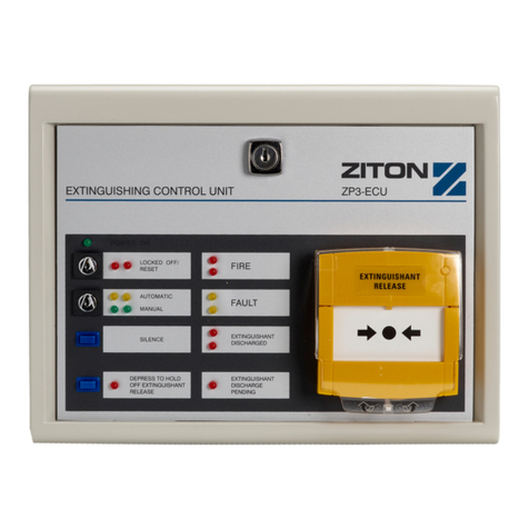
• Check the front panel of the ECU and any status units. Only the POWER ON
and Automatic/Manual LEDs should be illuminated.
• Test the function of the Automatic/Manual key switch by operating the switch.
Check that the printer (if available) on the fire alarm control panel indicates
the change in switch position.
• Restore the system to previous configuration.
• Log the test in the system log.
Quarterly maintenance
Quarterly maintenance must be carried out by suitably trained personnel. Such
personnel may be direct employees of the company, or may be contracted from
the maintenance company responsible for servicing.
Quarterly maintenance is designed to pre-empt any problems that may arise and
to check that the system is functioning to its installation specifications. The
services should be arranged through a maintenance contract with a servicing
company. This agreement should specify how to contact the service company
and how they can access the premises.
Repair services should be available within 24 hours. For premises in continuous
use, an engineer should be on call at all times. The servicing company should
have engineers trained in servicing Ziton equipment. The owner of the fire alarm
system is responsible for ensuring that the company contracted is competent to
carry out the work.

Chapter 1: Maintenance
6 ZP3-ECU Extinguishing Control Unit Maintenance Manual
Quarterly maintenance – Extinguishing Status Units
If any ZP3-ECUS status units are attached to the ECU, check that their LED
indicators mirror those of the ECU.
With the actuator still disconnected, do the following:
1. Remove jumper L1 from the extinguishing display board of the ZP3-ECUS
status unit most remote from the ECU. Check that the Fault LEDs illuminate
on both the status unit and the ECU. Check that the fire alarm control panel
indicates a fault.
2. Reinsert jumper L1 that was removed in the above step. Check that the Fault
LEDs go out on both the status unit and the ECU. Accept and Reset the fault
on the control panel.
3. Repeat steps 1 and 2 above, but using jumpers L2 and L3 instead of
jumper L1.
4. Activate one of the inputs mapped to activate the ECU (using canned smoke
to activate a smoke detector if required).
5. Check that the red Fire LEDs on the front fascia of the status units illuminate.
6. Silence the fire bell output on the ECU by means of the Silence button on the
front fascia of the status unit. Check that the bell output responds accordingly.
7. Activate the second input mapped to activate the ECU (using canned smoke
to activate a smoke detector if required).
8. Check, after the delay time, that the Extinguishant Discharged LED on the
front fascia of the status unit is illuminated, while monitoring the time taken for
this operation.
9. Turn the Locked Off/Reset key switch on the front fascia of the status unit and
check that the Locked Off/Reset LEDs on the ECU and status units illuminate.
Check that the extinguishant discharge siren connected to the ECU silences.
10.Accept and reset the fire alarm control panel by turning the Locked Off/Reset
key on the status unit to Reset. Check that the Locked Off/Reset LEDs go off
on the ECU and status units.
11.Test the hold off operation by completing tests in steps 1, 2, 4, 5, 6, and 7
above. Wait 10 seconds and press the Hold Off Extinguishant Release
button. Measure the time between the activation of the Extinguishant
Discharged LEDs and releasing the Hold Off Extinguishant Release button.
The measured period, which is the configured delay setup by VR1 (on the
main board), should be the same as the time noted in step 8. Confirm that this
is the correct delay time required.
12.Repeat steps 9 and 10 to reset the unit.

Chapter 1: Maintenance
ZP3-ECU Extinguishing Control Unit Maintenance Manual 7
Arming the system after quarterly maintenance
After successfully completing the maintenance check, do the following:
• Submit a report of the findings to the system owner or his delegated
representative.
• Restore the system to normal and reset.
• Lock the system off while restoring the actuator.
• Remove the transit pin from the extinguisher cylinder (if applicable).
Fault finding
Faults that occur on the ECU or in building wiring are reported by the fire alarm
control panel. The Fault LED on the ECU front panel illuminates. When a fault
occurs, it should be dealt with as quickly as possible. In some cases the operator
will be able to rectify the fault, but usually a call will be made to the servicing
company.
A comprehensive guide to faults that can be raised by the panel is provided in
Chapter 3 “Fault finding – ECU faults” on page 15. Information is also given as to
the appropriate actions to take in each case.

Chapter 1: Maintenance
8 ZP3-ECU Extinguishing Control Unit Maintenance Manual

ZP3-ECU Extinguishing Control Unit Maintenance Manual 9
Chapter 2
Fault finding –
communication
Summary
This chapter provides information on tracing and correcting faults communicated
from the ECU to the fire alarm control panel.
Note: Fault messages on the fire alarm control panel display depend on the
control panel used. The examples included in this chapter are for the ZP3 Fire
Alarm Control Panel. For other control panels, refer to the documentation for the
control panel.
Content
General Information 10
Precautions 10
Device unaccepted 11
Relay not responding 12
Device type fault 13
Device offline 14

Chapter 2: Fault finding – communication
10 ZP3-ECU Extinguishing Control Unit Maintenance Manual
General Information
When tracing and correcting faults, observe the following guidelines and
precautions:
• Before starting any fault finding procedures, make sure that the system as a
whole is calibrated correctly. Check the high reference analogue (reading 1)
from several devices covering the length of the loop. The reference value
should be between 205 and 218.
• If there appears to be a problem, disconnect the loop and connect a single
detector to the panel. Check that the reading is within the above parameters.
• When tracing a fault on a device or alarm line, the recommended procedure is
to split the line in half and check in which half the problem is located.
Continue this procedure, dividing the suspect region of the line in half until the
exact location of the problem is identified.
Precautions
• Never use a megger (or any other high-voltage instrument) on detection or
alarm lines while there are any devices connected to them. This causes
irreparable damage to the devices.
• Never replace a panel PCB, or any other components while the power is
connected. This could damage them irreversibly.
• Never replace a fuse with one that has a higher amperage rating than that
specified.
• Whenever replacing loop devices make sure that the address settings on the
replacement units match those of the units they are replacing.
The fault list describes faults that can be raised by the fire alarm control panel.
The following information is given for each fault:
• Fault name
• Fault description
• Panel indications
• Possible causes
• Corrective actions
Panels are configured to sound a fault buzzer when a fault is raised. The buzzer
sounds approximately every three (3) seconds. A yellow Fault LED also
illuminates. After acknowledging the fault by accepting it, the buzzer sounds only
every fifteen (15) seconds. After correcting the fault, reset the panel – this returns
the panel to normal status and the Fault LED goes out.

Chapter 2: Fault finding – communication
ZP3-ECU Extinguishing Control Unit Maintenance Manual 11
Device unaccepted
During initialisation on power up the panel checks all devices, noting the device
type at each address. This process can also be initiated through the Setup menu
(see the fire alarm control panel installation manual). A device Unaccepted fault
is raised when a device cannot be accepted.
Indications
• The yellow Fault LED is lit.
• The fault buzzer sounds.
• The event is shown on the display, for example:
UNACCEPTED Zone 001 Dev 001 Event 001
Second Floor, Laundry Room
• The event is printed (if a printer is configured).
Possible causes
If the unaccepted devices refer to an ECU, the possible causes are:
• Open circuit, short circuit, or missing end-of-line (EOL) resistors on field
wiring.
• Loop wiring out of specification (resistance/capacitance).
• Loose or high resistance connection on the field wiring terminals.
• An ECU that is out of calibration or is faulty.
• Interference on the loop to which the device is attached.
Corrective actions
1. Press the Accept/Panel Silence button to silence the buzzer and to
acknowledge the fault. If this fault has been raised for a number of devices on
the same loop then there may be interference on the loop. If this does not
apply then proceed to the next point.
2. Note the ECU in need of attention, and then show the analogues for the two
addresses applicable to that device on the display by using the maintenance
menu report analogue facility.
3. Check that slot 5 analogue reading is not less than 59 counts or more than
188 counts. Above or below would indicate an open circuit or shorts on the
field wiring respectively.
4. The extinguishing relay reading should also have an analogue reading in
slot 6 of between 39 and 198.
5. Take the appropriate actions to fix the problems identified in steps 3 or 4.
6. Remove power from the panel and then re-apply power. This initialises the
panel and the devices and the previously unaccepted device should now be
accepted.

Chapter 2: Fault finding – communication
12 ZP3-ECU Extinguishing Control Unit Maintenance Manual
Relay not responding
This fault is raised when the ECU double knock relay does not switch when
required. The relay is mapped as an output that is activated by a triggered input.
Indications
• The fault buzzer sounds.
• The display scrolls between two events, one showing the addressable relay
device that has not switched, the other showing the event that has triggered it
(usually a fire event). For example:
FIRE Zone 001 Dev 001 Event 001
Second Floor, Laundry Room
RELAY FAULT Zone 001 Dev 086 Event 002
• The event is printed (if a printer is configured).
• Zone in which the relay fault occurred is indicated by the appropriate red
Zone LED.
Possible causes
• The ECU double knock relay is in an isolated state.
• The ECU double knock relay is faulty.
Corrective actions
1. Press the Accept/Panel Silence button to silence the buzzer and to
acknowledge the fault.
2. If the yellow Isolated LED is on, check whether the relay is isolated. If the
relay is isolated then investigate the reasons for this. De-isolate the relay if it
is safe to do so.
3. If no other reason can be found for the fault, replace the faulty ECU main
board.
4. Reset the panel.

Chapter 2: Fault finding – communication
ZP3-ECU Extinguishing Control Unit Maintenance Manual 13
Device type fault
When the system is commissioned the panel notes the device type at each
address. If this type should subsequently change then the panel raises a device
type fault.
Indications
• The yellow Fault LED is lit.
• The fault buzzer sounds.
• The event is shown on the display, for example:
TYPE FAULT Zone 001 Dev 001 Event 001
Second Floor, Laundry Room
• The event is printed (if a printer is configured).
Possible causes
• Device addresses have been swapped within the system after device
acceptance.
• System interference caused by faulty wiring.
Corrective actions
1. Press the Accept/Panel Silence button to silence the buzzer and to
acknowledge the fault.
2. Check the system specification to see which type of device should be at the
address in question. Replace the incorrect device with one of the correct type.
3. Reset the panel.

Chapter 2: Fault finding – communication
14 ZP3-ECU Extinguishing Control Unit Maintenance Manual
Device offline
The panel checks all devices during initialisation on power up, and notes the
device type at each address. This process can also be initiated through the
Setup menu (see the fire alarm control panel installation manual). If an ECU
device is missing at an address that was previously occupied then the panel
detects that it is offline.
Indications
• The yellow Fault LED is lit.
• The fault buzzer sounds.
• The event is shown on the display, for example:
DEV OFFLINE Zone 001 Dev 001 Event 001
Second Floor, Laundry Room
• The event is printed (if a printer is configured).
Possible causes
• An isolator on the loop has caused the device to open circuit.
• Field wiring is disconnected or there is an open circuit.
Corrective actions
1. Press the Accept/Panel Silence button to silence the buzzer and to
acknowledge the fault.
2. Note the faulty device and then show the analogues for that device on the
display. Check the first analogue reading. If analogue reading 1 is almost at
zero then the panel cannot communicate with the device.
3. Install a replacement if the device is missing. If the device is present then
remove it and check the lloop for pulsing voltage on the device terminals. If
there is no loop voltage present then fix the fault in the field wiring or replace
the appropriate loop isolator.
4. Make sure the device is correctly in place and reset the panel.
Other manuals for ZP3-ECU
4
Table of contents
Other Ziton Control Unit manuals
Popular Control Unit manuals by other brands

Moons'
Moons' STF-C Series Hardware manual

WOMIX
WOMIX MIX M Series Mounting and operating instructions

Sennheiser
Sennheiser UUSB 8 instruction manual

Genebre
Genebre 2108 Installation, operation and maintenance manual

Beyerdynamic
Beyerdynamic MCW-D 200 Features and specifications

Nexans
Nexans XPLORER 144 - 3X48 Notice Instructions

VAT
VAT 650 Series Installation, operating, & maintenance instructions

Graco
Graco Advanjet HV-2000b Setup and operation

Honeywell
Honeywell ADEMCO 4204 installation instructions

ASCO Valves
ASCO Valves USM8260101 Installation & maintenance instructions

AppconWireless
AppconWireless RF1276MN instruction manual

Pilz
Pilz PNOZ m0p operating instructions