08.06.2021
Technische Änderungen und Irrtümer vorbehalten. / Technical changes and errors excepted.
Elsner Elektronik GmbH • Sohlengrund 16 • 75395 Ostelsheim • Deutschland • www.elsner-elektronik.de • Service: +49 (0) 7033 / 30945-250
D
KNX PS640 4U
70146
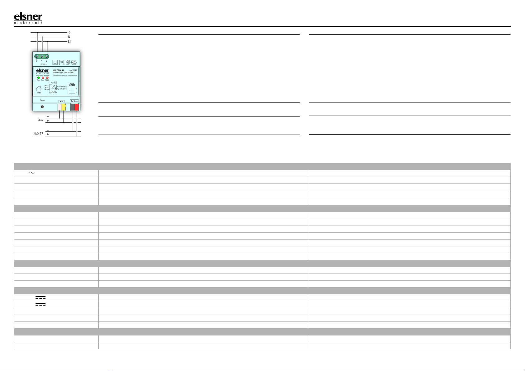
Fig. 1
DE Aufbau des Geräts
1 Busspannung VBUS
grün: VBUS ist 28…31 V DC
[off]: VBUS ist außerhalb dieses
Bereichs
2 Ausgangsstrom IOUT
[off]: IOUT < 900 mA
rot: IOUT > 900 mA (Überlast)
3 KNX-Bus Reset
rot: Neustart der KNX-Linie wird
durchgeführt
A Netzanschluss
B Resettaste
C Hilfsspannungsanschluss
DKNXTPAnschluss
EN Device structure
1 Bus voltage VBUS
green: VBUS is 28…31 V DC
[off]: VBUS is out of this range
2 Output current IOUT
[off]: IOUT < 900 mA
red: IOUT > 900 mA (Overload)
3 KNX bus reset
red: Restart of the KNX bus line
is running
A Supply voltage terminals
B Reset button
C Aux output connector
D KNX TP connector
Spannungsversorgung KNX-Bus/Hilfsspannung
Installationshinweise
Sicherheits- und Gebrauchshinweise
Produktdatei (ETS 5-Applikation) finden Sie auf der Homepage von Elsner Elektronik unter
www.elsner-elektronik.de im Menübereich „Service“ zum Download.
Installation und Inbetriebnahme dürfen nur von einer Elektrofachkraft durchgeführt
werden.
GEFAHR!
Lebensgefahr durch elektrische Spannung (Netzspannung)!
Im Innern des Geräts befinden sich ungeschützte spannungsführende Teile.
• Nehmen Sie nur unbeschädigte Geräte in Betrieb.
• Halten Sie die vor Ort geltenden Richtlinien, Vorschriften und Bestimmungen für die elektrische
Installation ein.
• Nehmen Sie das Gerät bzw. die Anlage unverzüglich außer Betrieb und sichern Sie sie gegen
unbeabsichtigtes Einschalten, wenn ein gefahrloser Betrieb nicht mehr gewährleistet ist.
Verwenden Sie das Gerät ausschließlich für die Gebäudeautomation und beachten Sie die Ge-
brauchsanleitung. Unsachgemäße Verwendung, Änderungen am Gerät oder das Nichtbeachten
der Bedienungsanleitung führen zum Erlöschen der Gewährleistungs- oder Garantieansprüche.
Betreiben Sie das Gerät nur als ortsfeste Installation, das heißt nur in montiertem Zustand und nach
Abschluss aller Installations- und Inbetriebnahmearbeiten und nur im dafür vorgesehenen Umfeld.
Beschreibung
Die Spannungsversorgung KNX PS640 4U ist eine 640 mA KNX Busspannungsversorgung und
dient zur Versorgung einer TP-Linie im KNX Bussystem. Die KNX PS640 4U verfügt auch über ei-
nen zusätzlichen, unverdrosselten Ausgang zur Hilfsstromversorgung, z. B. zur Versorgung einer 2.
Linie (nur mit zusätzlicher Drossel). Ebenso können KNX-Geräte die eine zweite Versorgungsspan-
nung benötigen, mit dem zusätzlichen Ausgang betrieben werden.
Beide Ausgänge sind überlastsicher und kurzschlussfest. Der KNX-Bus kann per Tastendruck zu-
rückgesetzt werden. Die Trennung vom Bus während des Resets wird mit einer LED angezeigt. LEDs
für KNX-Spannung und Ausgangsstrom zeigen Normalbetrieb bzw. Überlast an.
Lieferumfang
• Spannungsversorgung
• KNX-Klemme (rot/schwarz) und Hilfsspannungsklemme (weiß/gelb)
Installation
Montageort und Vorbereitung
• Installation nur in trockener Umgebung. Gerät vor Feuchtigkeit, Schmutz und Beschädigung
schützen
• Der Zugang zum Gerät muss für Bedienung und Inspektion stets gewährleistet sein
• Das Gehäuse des Geräts darf nicht geöffnet werden
• Zur Montage ein geeignetes Werkzeug nach IEC60715 verwenden
• Installation nur in Verteilerkästen oder geschlossenen Gehäusen. Installation nur auf geeigneter
DIN-Hutschiene (TH35). Stromführende Teile müssen vollständig abgedeckt werden. Die Abde-
ckung darf nicht ohne Hilfe eines Werkzeugs zu entfernen sein. Der Berührschutz muss durch den
Schaltschrank gewährleistet sein
Anschluss
• Der Anschluss erfolgt per Schraub- und Busklemmen
• Die KNX-Buslinie, wie für alle üblichen KNX-Anschlüsse, mit abisoliertem KNX-Buskabel und
KNX-TP-Klemme anschließen. Beim Anschließen nicht die elektrische Isolationen beschädigen
Betrieb
In KNX-Netzwerkinstallationen versorgt die KNX PS640 4U eine KNX-TP-Linie. Der ETS- (Dummy)
Datenbankeintrag der KNX PS640 4U ist ab der ETS4 verfügbar. Die Datenbank ohne Parameter
und ohne Kommunikationsobjekte kann wie gewohnt in ein ETS-Projekt eingefügt werden.
Applikation
KNX PS640 4U hat keine Parameter und keine Kommunikationsobjekte. Eine individuelle Adresse
kann nicht in das Gerät geladen werden.
Power Supply KNX bus/Auxiliary Voltage
Installation instructions
Safety and operating instructions
Product file (ETS 5 application) can be downloaded from the Elsner Elektronik website on
www.elsner-elektronik.de in the “Service” menu.
Installation and operational start-up should only be performed by an electrician.
DANGER!
Risk to life from live voltage (mains voltage)!
There are unprotected live components inside the device.
• Only put undamaged devices into operation.
• Comply with the locally applicable directives, regulations and provisions for electrical installation.
• Immediately take the device or system out of service and secure it against unintentional switch-
on if risk-free operation is no longer guaranteed.
Use the device exclusively for building automation and observe the operating instructions. Impro-
per use, modifications to the device or failure to observe the operating instructions will invalidate
any warranty or guarantee claims.
Operate the device only as a fixed-site installation, i.e. only in assembled condition and after con-
clusion of all installation and operational start-up tasks, and only in the surroundings designated
for it.
Description
The Power Supply KNX PS640 4U is a 640 mA KNX bus power supply to supply one TP line of
a KNX system with power. The KNX PS640 4U also features an additional unchoked output. This
auxiliary output can be used, for example, to supply a second line (only with additional choke). De-
vices which require a second supply voltage can be supplied.
Both outputs are overload-proof and short circuit protected. The KNX bus can be reset by push-but-
ton. Bus disconnection during reset is indicated by a LED. Further LEDs, for KNX bus voltage and
total output current, indicate normal operation and overload.
Scope of delivery
• Power Supply System
• KNX terminal (red/black) and auxiliary voltage terminal (white/yellow)
Installation
Installation location and preparation
• Installation only in dry locations. Protect the device from moisture, dirt and damage
• Accessibility of the device for operation and visual inspection must be provided
• The housing of the device must not be opened
• For mounting use an appropriate equipment according to IEC60715
• Installation only in distribution boards and enclosed housings. Installation only on a 35 mm DIN
rail (TH35). Terminals and metal parts under current must be completely covered. It must be not
possible to remove the cover without aid of a tool. Contact protection must be provided through
the control cabinet
Connection
• Connections are made by screw and bus terminals
• Connect the KNX bus line as for common KNX bus connections with a KNX bus cable, to be strip-
ped and plugged into the KNX TP connector. Do not damage electrical insulations when connec-
ting
Operation
In KNX network installations KNX PS640 4U supplies one KNX TP line. The KNX PS640 4U's
ETS (dummy) database entry is available for ETS4 and upward. The database without parameters
and without communication objects can be added to an ETS project as usual.
Application
KNX PS640 4U has no parameters and no communication objects. An individual Address cannot
be downloaded to the device.
EN