BEHR behrotest R 104 T User manual

behr
Labor-Technik
197109
R 104T
R 106T
R 108T
behrotest®
In-Line Extraction Units
With Glassware for Twisselmann Extraction
User’s Manual

– 2 –
197109
© behr Labor-Technik GmbH
behrotest®In-Line Twisselmann Extraction Unit
Please read this User’s Manual carefully before using your new
behrotest® In-Line extraction apparatus!
The User’s Manual provides you with clear and simple instructions for using the apparatus.
In the interest of insuring safe utilization of the In-Line-Extraction apparatus,
observe carefully the safety warnings in the manual, which are designated by a !
Additional useful and important information on the functioning of the apparatus is
marked by a stripe in the margin.
We wish you success and satisfaction in the use of your
behrotest®
In-Line Twisselmann Extraction apparatus

– 3 –
197109
© behr Labor-Technik GmbH
behrotest®In-Line Twisselmann Extraction Unit
Safety Warnings
Danger of toxic solvent vapours! Always conduct the extraction in a fume
hood.
Danger of electric shock! Make sure that no liquids get into the cable
connections or the inside of the equipment.
Be careful in working with chemicals! Follow the safety guidance in the
pertinent Safety Data Sheets.
Glass can break and cause injury! In working with glass components,
observe all appropriate safety precautions.
Caution: vessels get hot and can cause burns! Do not touch the solvent
vessels and extractors with bare hands during and immediately after an
extraction.
Danger of fire or explosion! Do not spill solvents on the hot heating plates.
The device is not suitable for extraction with diethyl ether or other highly
inflammable solvents.

– 4 –
197109
© behr Labor-Technik GmbH
behrotest®In-Line Twisselmann Extraction Unit
Contents
Safety Warnings .................................................................................................. 3
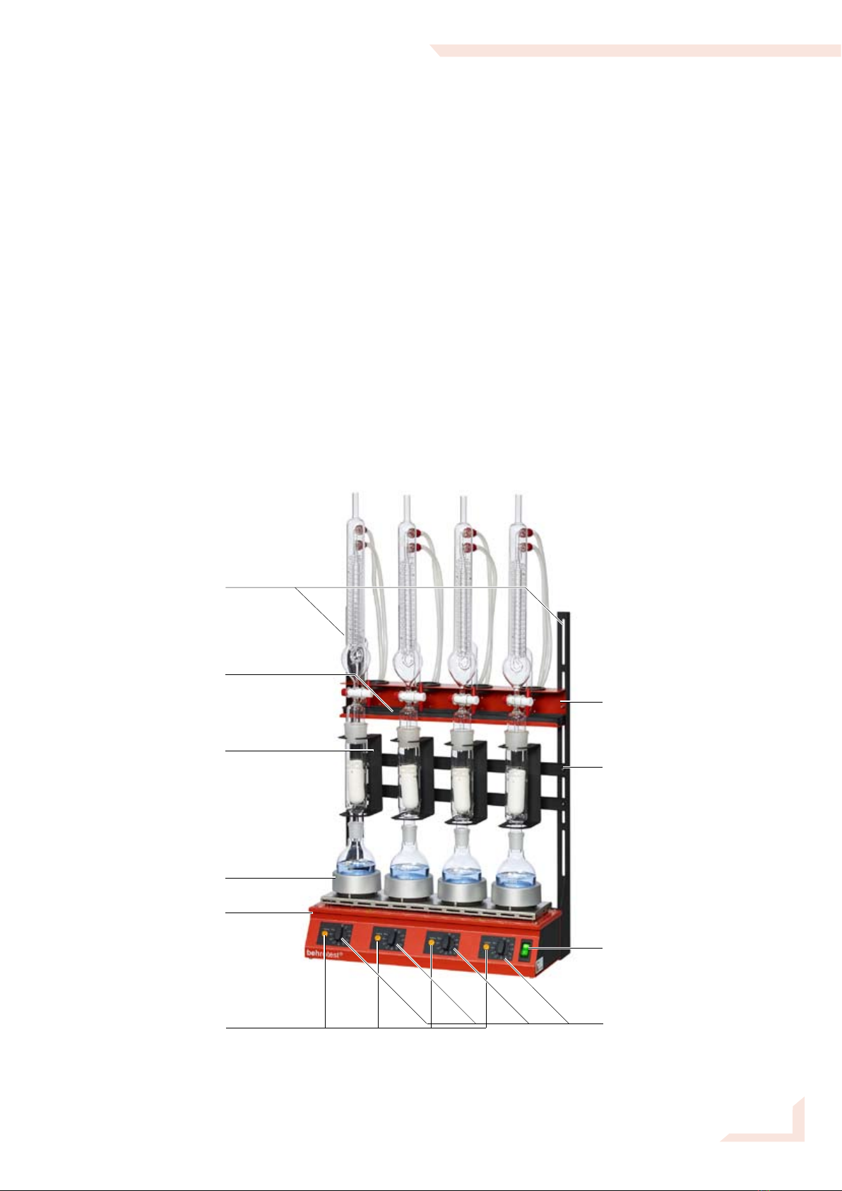
Description........................................................................................................... 5
Contents of Delivery ........................................................................................... 6
Completeness and absence of damage ........................................................................... 6
List of Components ........................................................................................................... 6
Appropriate Use .................................................................................................. 8
Assembling the behrotest®In-line extraction unit........................................... 9
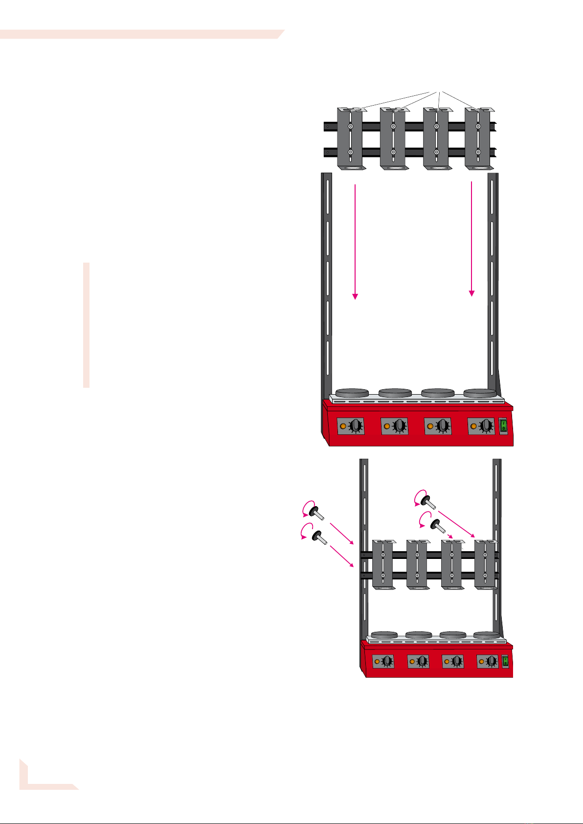
Attaching the Vertical Support Bars .................................................................................. 9
Attaching theHorizontal Support Bars............................................................................. 10
Installing theFlask Adapters ........................................................................................... 12
Inserting the Glassware .................................................................................................. 12
Connecting the Water Hoses .......................................................................................... 14
Using a Model UK 12Circulating Water Cooler............................................................... 16
Connecting to the Mains Power Line .............................................................................. 17
Leak Testing .................................................................................................................... 17
Using the inline extraction unit........................................................................ 18
Sample preparation......................................................................................................... 19
Switching the heating unit on .......................................................................................... 19
Starting the Extraction..................................................................................................... 20
Finishing the Extraction................................................................................................... 20
Cleaning the In-Line Extraction Apparatus .................................................... 21
Spare Parts and Accessories........................................................................... 22
Technical Specifications .................................................................................. 22
Customer Service.............................................................................................. 22

– 5 –
197109
© behr Labor-Technik GmbH
behrotest®In-Line Twisselmann Extraction Unit
Description
The behrotest® In-Line Extraction Unit is used for Twisselmann extraction, mainly in food,
foodstuffs and soil analysis.
Depending on the model and configuration, the apparatus consists of either four, six, or
eight individually adjustable heating positions for round-bottom flasks of 250 ml, along with
100-ml extractors and the matching condensers.
The full capabilities of the behrotest® In-Line Extraction Unit in daily laboratory utilization
can only be realized if you carefully read and follow all of the guidance in this manual.
Vertical support bars
Drip pan
Adjustable extractor
mounts
Hot-plates with flask
adapters
In-line hot plates
Heating power
adjustments
On/Off switch
with built-in circuit
breaker
Crossbars for the
extractor mounts
Cooling water
distributor with
condenser stand
Heating indicator lights

– 6 –
197109
© behr Labor-Technik GmbH
behrotest®In-Line Twisselmann Extraction Unit
Contents of Delivery
Completeness and absence of damage
Immediately on receipt, check the contents of the delivery for absence of damage and
completeness.
A claim for damage in transport which is evident on the outside of the packing, must be
immediately submitted to the carrier (postal , rail or road haulage carrier) – see the shipping
label on the package.
If components are damaged, but no damage to the external packing was evident
(concealed transport damage), contact the behr customer service immediately (also in the
event of other complaints). The address is:
behr Labor-Technik GmbH
Spangerstraße 8
D-40599 Düsseldorf / Germany
Phone: +49 211 7 48 47 40
Telefax: +49 211 7 48 47 48
eMail: info@behr-labor.com.
List of Components
All behrotest® In-Line Extraction Units consist of a
Basic unit for four or six samples
1 In-line hot-plate array R 4 (4 hot plates) or R 6 (6 hot plates)
2 Vertical support bars
1 Cooling water distributor with condenser stand (4 or 6 place) and drip pan,
1 Crossbar with 4 or 6 adjustable extractor mounts
1 Water inflow hose, polyamide, Ø 8 mm
1 Water outflow hose, PVC, Ø 12 mm
1 Disconnecting tool for Speedfit hose connections
1 Connection for ¾“ pipe thread water tap
1 Adapter for ½“ pipe thread water tap
1 User’s Manual (this one)

– 7 –
197109
© behr Labor-Technik GmbH
behrotest®In-Line Twisselmann Extraction Unit
Depending on the model, the following complete extraction glassware is
provided:
R 104 T
4 Aluminium hotplate adapters to fit 250-ml round bottom flasks
4 250-ml round bottom flasks (RK 250)
4 distance pieces for round-bottom flasks
4 Twisselmann extractors, 100 ml (EZT)
4 Spiral coil reflux condensers for Twisselmann (RFKT)
8 Silicone tube, 6 x 2 mm, cuttings of 50 cm
R 106 T
6 Aluminium hotplate adapters to fit 250-ml round bottom flasks
6 250-ml round bottom flasks (RK 250)
6 distance pieces for round-bottom flasks
6 Twisselmann extractors, 100 ml (EZT)
6 Spiral coil reflux condensers for Twisselmann (RFKT)
12 Silicone tube, 6 x 2 mm, cuttings of 50 cm
R 108 T
8 Aluminium hotplate adapters to fit 250-ml round bottom flasks
8 250-ml round bottom flasks (RK 250)
8 distance pieces for round-bottom flasks
8 Twisselmann extractors, 100 ml (EZT)
8 Spiral coil reflux condensers for Twisselmann (RFKT)
16 Silicone tube, 6 x 2 mm, cuttings of 50 cm
Options:
Hydrolysis unit EXR 4 and filtration unit FU 4 (4 samples) or
Hydrolysis unit EXR 6 and filtration unit FU 6 (6 samples) or
Hydrolysis unit EXR 8 and filtration unit FU 8 (8 samples)
Circulating water coolers for condensers – UK 12/1000 or UK 12/2000

– 8 –
197109
© behr Labor-Technik GmbH
behrotest®In-Line Twisselmann Extraction Unit
Appropriate Use
The in-line heating unit serves for heating
samples in appropriate vessels, as, for
example, fat extraction with petroleum
ether or heating under reflux. Round-
bottom flasks and other vessels with small
contact surface may only be used with the
appropriate flask adapters. Heating the unit
without dissipating the heat that is being
produced can destroy the heating plates.
The in-line heating unit is not suitable
for non-intermittent operation at high
temperature.
Do not make arbitrary alterations in the unit.
These could affect its safety and reliability
and will void the product guarantee.
Do not expose the device to aggressive
vapours e.g. of acids, bases or solvents!
Non-appropriate use will make the
guarantee void.
The in-line heating unit must only be
connected to a mains receptacle of
sufficient load capacity. For the 8-place
versions, a fuse protection of 16 A is
recommended.

– 9 –
197109
© behr Labor-Technik GmbH
0
l
0
l
behrotest®In-Line Twisselmann Extraction Unit
Assembling the
behrotest®In-line extraction unit
Danger of toxic solvent vapours! Always conduct the extraction in a fume
hood.
Danger of electric shock! Make sure that no liquids get into the cable
connections or the inside of the equipment.
Glass can break and cause injury! In working with glass components,
observe all appropriate safety precautions.
Attaching the
Vertical Support Bars
Place the in-line heating unit on a flat level
surface.
Attach both vertical support bars to the
side of the in-line heating unit using the
four knurled screws provided.
Befestigen Sie die beiden Standpfosten
mit den 4 Rändelschrauben an der
Rückseite der Reihenheizbank.
Make sure the lower ends of the support
bars, which are to be attached to the
heating unit, are resting on the bench
top. The angle bracket for attaching the
support bars has elongated slots for
inserting the screws. This allows you to
adjust the vertical height of the support
bars.
Angle brackets
with elongated
slots

– 10 –
197109
© behr Labor-Technik GmbH
0
l
0
l
behrotest®In-Line Twisselmann Extraction Unit
Attaching the
Horizontal Support Bars
Bars with Extractor Mountings
Insert the bars with the extractor
mountings from below between the
internal track formed by the horizontal
support bars. The extractor mountings
must be oriented with the slotted
opening on top, facing forward.
The correct height of attachment for the
horizontal support bars depends on the
glassware being used. For example,
in the case of the 100 ml Soxhlet
extraction, locate the screw holes of
the upper horizontal support bar at the
lower ends of the third elongated slots
in the vertical support bars. The height
can be readjusted as needed at any
time in the future.
Fasten the horizontal support bars with
the four knurled screws provided.
Slotted openings

– 11 –
197109
© behr Labor-Technik GmbH
0
l
0
l
behrotest®In-Line Twisselmann Extraction Unit
Condenser stand
with cooling-water distributor
Insert the condenser storage stand from
above between the internal track formed
by the horizontal support bars.
Position the screwhole of the condenser
stand at the lower ends of the
uppermost elongated slots in the
vertical support bars.
Fasten the condenser stand in place
with the pair of knurled screws
provided.
Insert the drip tray into the condenser
storage stand.

– 12 –
197109
© behr Labor-Technik GmbH
0
l
0
l
behrotest®In-Line Twisselmann Extraction Unit
Inserting the Glassware
To minimize the risk of breakage,
always hold all glassware in the vicinity
of the standard taper joint!
Lay the cross-shaped distance parts into
the hotplate-flask adapters.
The round-bottom flasks must not be
immediately inserted in the hotplate-
flask adapters; otherwise they could
break on heating. Never operate your
in-line extraction unit without the
distance parts!
Place the round-bottom flask in the flask
adapter on the hotplate.
Check once more the height of the
crossbars with extractor mounts. The
upper end of the neck of the round
bottom flask must protrude several
millimeters into the lower opening of the
extractor mount. This will secure the
flask against tipping over. If necessary,
adjust the height of the crossbars.
Installing the
Flask Adapters
Place the hot-plate flask adapters on
the hotplates.
Take care that the adapters are seated
securely on the hotplates and cannot
slip off sideways.

– 13 –
197109
© behr Labor-Technik GmbH
0
l
0
l
behrotest®In-Line Twisselmann Extraction Unit
Insert the extractors from above into the
extractor mounts and seat them on the
round-bottom flasks.
The upper horizontal segment of the
extractor mounts have a slot in front.
In the event that you are using an
extractor with spigot (for example, the
behrotest®EZ 100/HAHN), then guide
the extractors with the spigots carefully
through these slots.
Insert the reflux condensers onto the
extractors.

– 14 –
197109
© behr Labor-Technik GmbH
behrotest®In-Line Twisselmann Extraction Unit
Connecting the Water Hoses
Cooling-Water Distributor
Cooling-water supply
The cooling water supply hose is made
of polyamide and is 2 meters long. If
necessary, shorten it as required.
Use only a very sharp blade, such as a
scalpel or box cutter to cut polyamide
hoses. The cut end must be free of
burrs and at a sharp right angle. Avoid
deformation of the hose. By this you
will get a leak-free seal in the push-on
fitting.
The connection for the cooling-water supply
hose is found on the rear of the condenser
stand.
Push one end of the water supply hose
as far as it will go into the connection.
In the same manner, attach the ¾“
water tap connection to the other end
of the hose.
Lead the water-supply hose to a
laboratory water tap.
Water tap with ¾“ pipe thread:
Insert a washer in the connector and
fasten the water supply hose to the
water tap by screwing the connector
onto the ¾“ pipe thread of the water tap.
Water tap with ½“ pipe thread:
Use the ¾“ to ½“ adapter.
Place a washer in the connector and
screw the adapter and connector
together. Then screw the adapter onto
the ½“ pipe thread of the water tap.
For a water tap with
½" threading, use the
¾ / ½" adapter. Here, too,
do not forget the
gadget ring!
For a water tap with
¾" threading, screw the
adapter to the water tap
directly. Do not forget the
gadget ring!
Firmly push the end of the
supply hose in the hose
adapter.
Push the supply hose
firmly into the socket on
the lower distributor line
as far as it will go

– 15 –
197109
© behr Labor-Technik GmbH
behrotest®In-Line Twisselmann Extraction Unit
Cooling-water outflow
The connection for the cooling water
outflow is likewise located on the rear of
the cooling water distributor with condenser
stand.
Insert the black tubing segment of the
outflow (drain) hose as far as it will go into
the hose receptacle.
Lay the hose to a sink or other drain.
Make sure that there are no tight
curves or kinks in the hose. If
necessary, shorten the hose to prevent
constrictions of this nature.
Connections to the Condensers
Attach the silicone tubing segments to
the tubing nipples on the cooling water
distribution unit identified as
„Kühlerabfluss“ (outflow) and
„Kühlerzufluss“ (inflow).
Attach the tubing segments to the
condensers.
The lower nipple on the reflux
condenser is for water inflow. Connect
the tubing segments coming from the
lower „Kühlwasserzufluss“ panel of
the cooling water distributor to these
nipples.
Connect the upper nipples of the
condensers in the same manner with
the upper „Kühlwasserabfluss“ panel of
the cooling water distributor.

– 16 –
197109
© behr Labor-Technik GmbH
behrotest®In-Line Twisselmann Extraction Unit
Disconnecting
the quick push-in connections
If needed, the connections of the polyamide
tubing or the tubing nipples can easily be
disconnected. Use the special tool provided
for this purpose.
Use the narrow slot of the tool for the
nipples and the inflow tube and the wide
slot for the outflow tube.
Tubing nipple quick push-in connector
Place the tool in front of the annular rim
of the quick connector.
With the other hand, grasp the tubing
nipple.
Press the annular rim inwards with the tool
while simultaneously pulling the tubing
nipple forwards and out of the cooling
water distributor.
Inflow/Outflow Quick Connector
Place the tool in front of the annular rim
of the quick connector of the hose.
With the other hand, grasp the hose.
Press the annular rim inwards with the
tool while simultaneously pulling the
hose forwards and out of the quick
connector.
Using a Model UK 12
Circulating Water Cooler
Follow carefully the instructions in the
UK 12 User’s Manual.
The hose set of the circulating water cooler
contains an adapter for connection to the
inflow and outflow hoses of the cooling
water distributor.
Attach the free end of the inlet hose with an
adapter. Insure that you push the end of the
hose into the connector as far as it will go.
Connect the inlet hose to the water outflow
outlet of the circulating water cooler.
Complete the circuit by collecting the outlet
hose of the cooling water distributor to the
inlet of the circulating water cooler.
Disconnect
tubing nipple
Press
annular rim
inwards
Press annular rim inwards
Pull out hose
Connect the outlet hose
(the thick green PVC hose)
directly to the IN connector
of the UK 12
... and push the hose
firmly into the end part
of the adapter.
For the inlet hose
of the apparatus
(the thin red hose) there
comes an adapter with
the UK 12 hose set.
Connect this adapter to
the OUT connector of
the UK 12...

– 17 –
197109
© behr Labor-Technik GmbH
0
l
behrotest®In-Line Twisselmann Extraction Unit
Connecting to the Mains Power
Line
First insure that the local mains (electrical)
power is of the same voltage as that
indicated on the model label of your
behrotest®inline apparatus.
Insure that the power switch on the front of
the inline apparatus is set to „0“.
Insert the plug of the electrical power cable
coming from the back of the inline heating
unit into a mains power socket.
Leak Testing
You can now check the hose and tubing
connections for leaks.
Turn on the water tap and make any
necessary changes to the hose and tubing
connections.

– 18 –
197109
© behr Labor-Technik GmbH
behrotest®In-Line Twisselmann Extraction Unit
Using the inline
extraction unit
Danger of toxic solvent vapours!
Always conduct the extraction in
a fume hood.
Danger of electric shock! Make
sure that no liquids get into the
cable connections or the inside
of the equipment.
Be careful in working with
chemicals! Follow the safety
guidance in the pertinent Safety
Data Sheets.
Glass can break and cause
injury! In working with glass
components, observe all
appropriate safety precautions.
Caution: vessels get hot and can
cause burns! Do not touch the
solvent vessels and extractors
with bare hands during and
immediately after an extraction.
Danger of fire or explosion! Do
not spill solvents on the hot
heating plates. The device is
not suitable for extraction with
diethyl ether or other highly
inflammable solvents.

– 19 –
197109
© behr Labor-Technik GmbH
1
2
3
behrotest®In-Line Twisselmann Extraction Unit
Sample preparation
Prepare the sample for extraction.
Place the sample material into the
extraction thimble. Close the top of the
thimble with fat-free cotton wool and
insert the closed thimble into the
extractor.
Insert the extractor into the extractor
mounting (1).
Now fill solvent into the round-bottom
flask. Place the flask on the hotplate
flask adapter (2) and insert the extractor
into the mouth of the flask (3).
Attach the reflux condenser to the
extractor and start the flow of cooling
water.
Switching the heating unit on
Turn the power switch on the front of the
inline heating unit to the „I“ position.
The power switch of the behrotest®
inline heating unit fulfills two functions.
It serves to turn the apparatus on and
off and also contains a built in electrical
circuit-breaker.
The circuit-breaker operates similarly to
those in household appliances – it shuts
off the electrical power supply.
Since this safety feature (circuit-breaker)
requires cocking a spring, turning the
power switch of the inline heating unit
to the on position will require somewhat
more force than a simple on/off switch.

– 20 –
197109
© behr Labor-Technik GmbH
behrotest®In-Line Twisselmann Extraction Unit
Starting the Extraction
Adjust the heat level for the individual
sample positions with the power level
knobs.
Adjust the power levels so that the
solvent boils uniformly in all positions
and condenses in sufficient amounts to
uniformly extract all of the samples.
The yellow „HEATING“ indicator lamps
of each heating position indicate heating
activity.
Finishing the Extraction
If you want to recover the solvent from the
extract, now close the stopcock in the reflux
condenser. The solvent evapoated from the
round-bottom flask will now collect in the
vessel in the lower part of the condenser;
you can use it for the next extraction.
After most of the solvent has been
evaporated, turn the power level knobs
down and switch the inline heating unit off
with the MAIN SWITCH.
This manual suits for next models
2
Table of contents
Other BEHR Laboratory Equipment manuals