CORRECT CRAFT LINC PANORAY User manual

LINC PANORAY
2021 OWNER’S MANUAL
FOR SELECT SUPER AIR NAUTIQUE MODELS

LINC PANORAY LINC PANORAY
2 3
BALLASTM E N U
Manual Tab
Set Level Tab
Overhead Tab (with Ballast Shift)
SWITCHIN G M E N U
Lights Tab
Courtesy Color Tab (Optional)
Climate Tab
Features Tab
MAP ME N U
Mini Map Tab
Full Map Tab
•Waypoints and Tracks
PREFERENCES ME N U
Settings Tab
Display Tab
System Tab
•Power Diagnostics
•EngineDiagnostics
•System Info
RIGHT S ECTIO N
Switchboard Tab
•Editing the Functions
Vitals Tab
WARNINGS ANDPOP UP MESSAG E
EngineDiagnostic Message
Circuit FaultMessage
TABLEOF CONTEN T S
OVERVIEW
Product Information
Care and Maintenance
Touchscreen Display
Helm Command
User Interface
•SplitInterface Mode
•GeneralLayout
•Fullscreen Mode and Layout
Using Helm Command
•Rotary Knob
•Button Shortcuts
•Volume Button
•User Button
•Speed Button
•Tab Button
•Home Button
HOMEM E N U
Main Tab
•Surf Speeds
•Wakeboard Speeds
•Ski Speeds (GS Series Only)
Status Tab
River Mode Tab
Steering Assist Tab (Optional)
AUDIO ME N U
Main Tab
Dynamic Source Tab
ZoneControl Tab
Audio Setup Tab
GOPRO ME N U
Control Tab
Settings Tab
•Connecting a GoPro Camera
Gallery Tab
5
5
6
7
9
10-11
1 3
14-19
2 0
2 1
22-24
2 5
2 6
2 7
28-31
2 8
2 9
3 0
3 2
33-35
36-39
40-41
42-43
4 4
45-46
4 8
49-53
50-53
54-55
5 6
5 7
5 9
6 0
61-63
6 4
6 5
6 6
67-69
68-69
7 0
7 1
72-75
7 3
7 4
7 5
76-79
77-79
8 0
8 2
8 3
P/N 210243

LINC PANORAY LINC PANORAY
4 5
OVERVIEW
PRODUCT INFORMATION
The Nautique LINC 3.0 system is designed for instrumentation and
control on electronically controlled engines communicating via SAE J1939
and NMEA 2000. The display is a multifunctional tool that provides GPS
tracking, multimedia display, speed control, and enables equipment
operators to view many dierent engine parameters and service codes.
CARE AND MAINTENANCE
General maintenance is not required; however, a soft cloth can be
used for cleaning the unit. Window cleaner or alcohol can also be used
to clean the glass portion of the display. Do not use harsh or abrasive
cleaners on the unit.

LINC PANORAY LINC PANORAY
6 7
OVERVIEW
TOUCHSCREEN DISPLAY
LINC Panoray features a 12.4” wide touchscreen display. Operators can
easily change settings and viewed information by tapping certain touch-
point icons on the screen. When the display recognizes that the operator
has touched the screen, a small, grey, circular graphic will appear at the
location where the operator has touched.
Operators can also scroll and swipe certain functions, lists and menus on
the touchscreen display.
To ensure proper use, make sure that hands and ngers are dry and
clean of any oils or lotions before touching the display.
OVERVIEW
HELM COMMAND
In addition to the touchscreen, the LINC 3.0 interface can also be fully
controlled with the Helm Command (pictured above) located on the
driver’s armrest adjacent to the throttle arm.
Helm Command features a machined, aluminum knob. This knob is able
to 1) rotate clockwise and counterclockwise, 2) tilt up, down, left and right
like a joystick and 3) can be pressed down like a button. The functions of
each of the three physical actions listed above can change depending on
the particular menu that is displayed.
A black, rubber keypad surrounds the knob with 5 dierent buttons.
These buttons act like shortcuts, or hot keys, and allow the user to
quickly jump to certain menus, tabs and frequently used settings.
Please refer to the following pages for a step-by-step instruction on how
to use Nautique’s Helm Command with the user interface.

LINC PANORAY LINC PANORAY
8 9
OVERVIEW
USER INTERFACE - SPLIT INTERFACE MODE
In most circumstances, the LINC Panoray interface is split into three, broad visual
sections; the center section, the left section and the right section.
CENTER SECTION - displays critical gauges, settings and functions (e.g. speed,
speed control on/o) that can be seen at a glance under most scenarios.
LEFT SECTION - displays specic, detailed information and functions which is
dictated mostly by the currently selected menu and menu tab. The operator
should use this section when he/she wants to take their time and get an “in-
depth” look into certain boat settings or features. For example, if an operator
wants to change individual audio settings, he/she should look at the left side of
the screen, navigate to the audio menu and select the proper menu tab to adjust
specic audio settings.
RIGHT SECTION - also displays information and functions, but is meant for
quicker operation. The right section does not use menus and contains only two
tabs at all times: the vitals tab and the switchboard tab. The vitals tab contains
vital engine gauges and information and the switchboard tab contains 4 dierent
functions that can be customized by the user (see pages 62-65). The switchboard
tab allows the operator to select his/her four favorite functions so that they
can be quickly adjusted (or turned on/o) from the right side without having
to navigate to any left side menus. Think of the switchboard tab as if it were
containing “shortcuts” to an operator’s most used/viewed features.
RIGHT SECTIONCENTER SECTIONLEFT SECTION

LINC PANORAY LINC PANORAY
10 11
OVERVIEW
USER INTERFACE - GENERAL LAYOUT
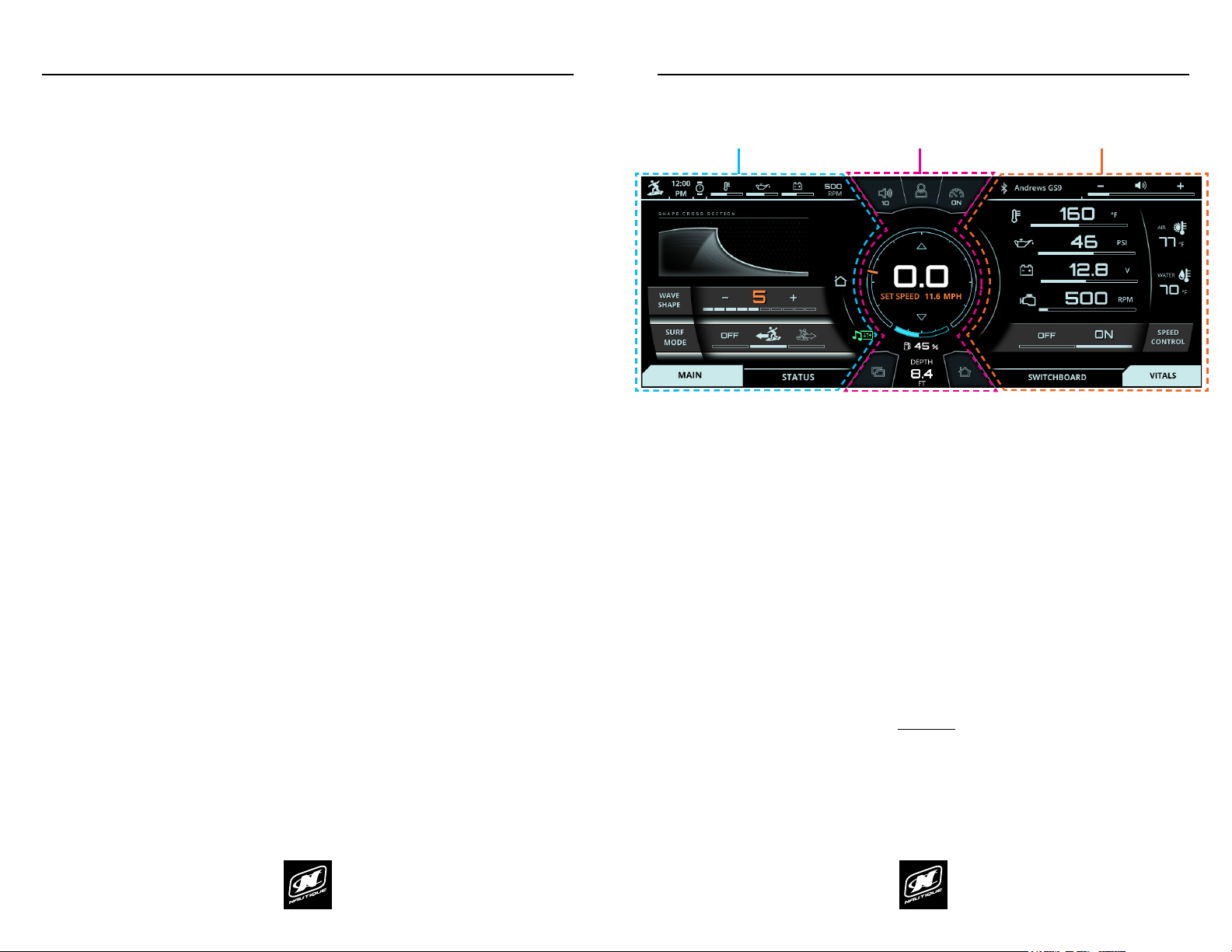
AREA FOR CRITICAL GAUGES & SETTINGS - This area displays the
current speed, set speed, speed control on/o, fuel gauge, and depth
gauge. This area also duplicates the 5 buttons on the Helm Command.
UPPER STATUS BAR - This area always displays the activated User
Prole, time, engine temperature, oil pressure, voltage, and RPM. The
operator can tap on the engine temperature, oil pressure, or voltage for
a numerical readout of that particular gauge. This area can also display
an icon for Surf Select if that setting is turned on.
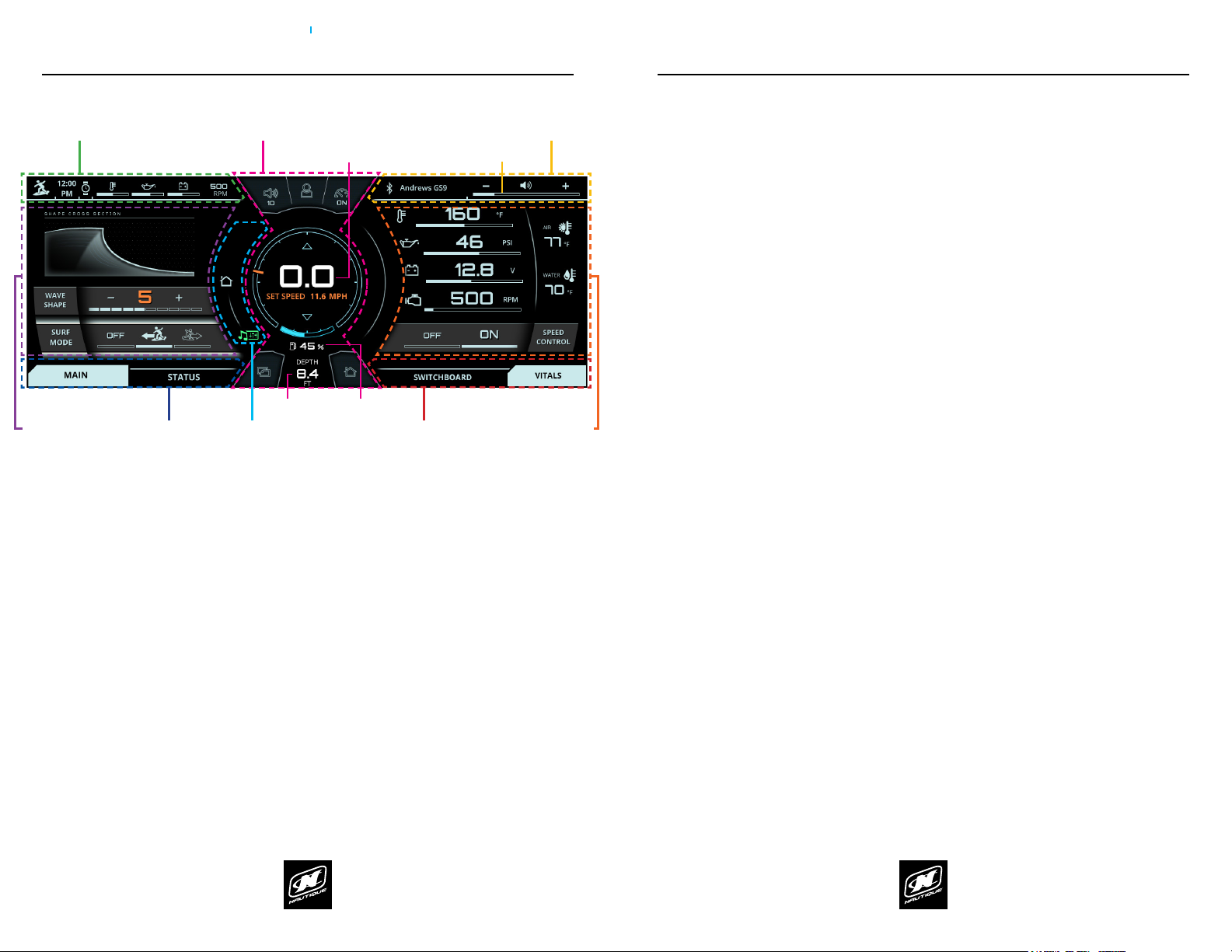
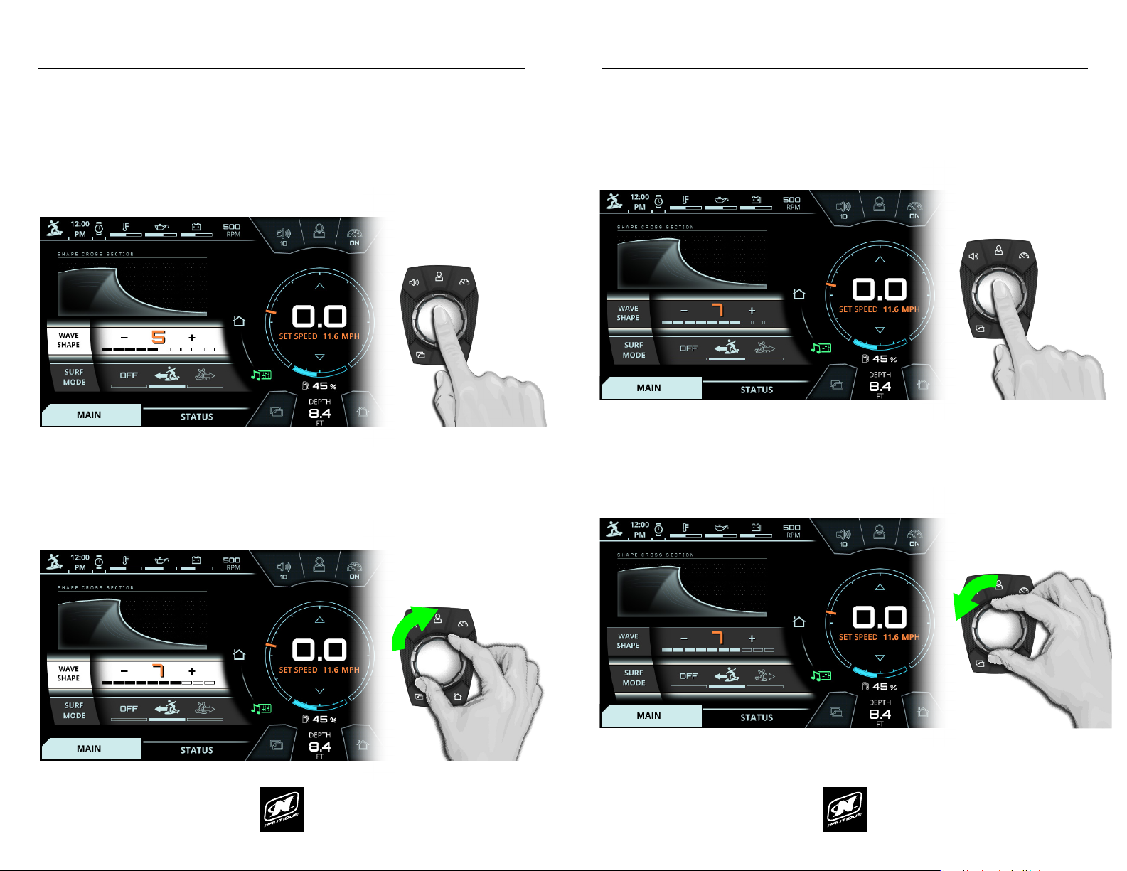
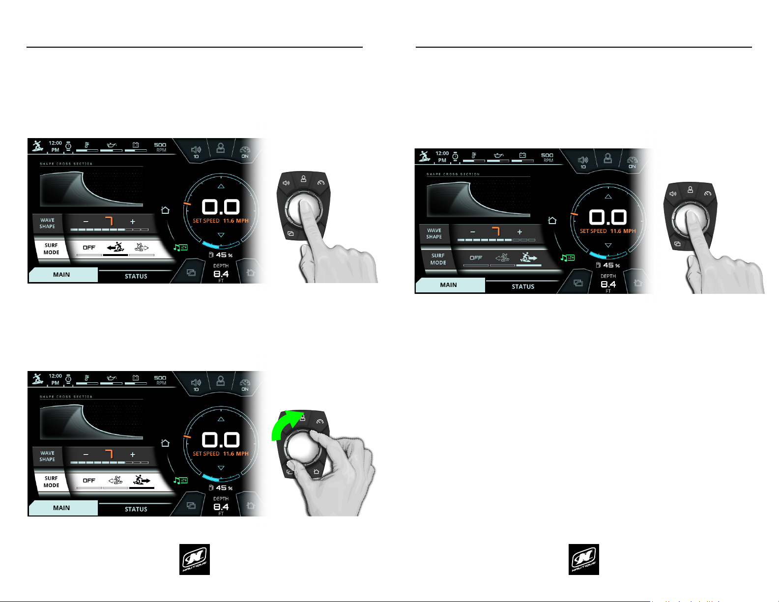
MENU WHEEL - Dierent menus can be selected here by tapping
individual menu icons or by rotating the Helm Command knob if the
Menu Wheel is highlighted. There can be up to 8 menus: Home, Audio,
Video, Ballast, Switching, User, Map, and Preferences. The middle icon of
the Menu Wheel shows which menu is currently being viewed.
MENU TAB BAR - This tab bar changes depending on the current menu.
Each tab contains a separate page of information that relates back to the
current menu. Menus contain either 2, 3 or 4 unique tabs.
USER INTERFACE - GENERAL LAYOUT (CONTINUED)
VIEWING AREA OF CURRENT MENU & MENU TAB (AKA “PAGE”) -
Each tab under each menu displays unique information, settings, and
functions in this area (which can be referred to as a “page”). Most settings
and functions are illustrated here as a stack-up of smaller horizontal bars
with curved ends.
AUDIO BAR - This area always displays the current stereo source and the
volume level of the audio system. Tapping the + or the - on the volume
level will increase or decrease the volume. Tapping the volume horn icon
will mute or unmute the audio system.
RIGHT TAB BAR - This tab bar always features two tabs: the switchboard
tab and the vitals tab. The switchboard tab features 4 functions that
can be customized by a user (see pages 62-65). The vitals tab (shown
in the screenshot) displays all of the vital engine gauges and system
information for the boat in a large, easy to read format. This includes
engine temperature, engine oil pressure, battery charging voltage, engine
RPM, air temperature and water temperature. The vitals tab also includes
the Speed Control On/O so that users can quickly turn that on or o as
needed.
VIEWING AREA OF CURRENT RIGHT TAB - this area will display
information, settings, and functions from the switchboard tab or the
vitals tab, whichever is selected.
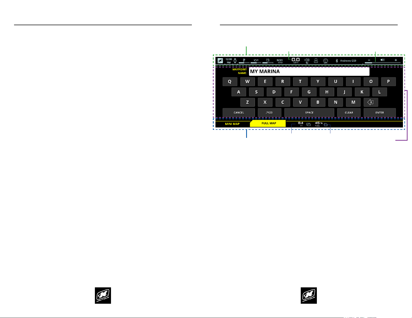
*NOTE: Certain menus and menu tabs from the left side may temporarily
occupy this space when there are more than 5 functions or settings.
UPPER STATUS BAR AUDIO BAR
MENU TAB BAR RIGHT TAB BAR
MENU WHEEL
CURRENT SPEED & SET SPEED VOLUME LEVEL
FUEL GAUGE
VIEWING AREA OF
CURRENT MENU &
MENU TAB
(AKA “PAGE”)
VIEWING AREA OF
CURRENT RIGHT TAB*
AREA FOR CRITICAL GAUGES & SETTINGS
OVERVIEW
DEPTH GAUGE

LINC PANORAY LINC PANORAY
12 13
USER INTERFACE - FULLSCREEN MODE AND LAYOUT
Some menus and menu tabs will adjust the appearance of the user interface in
order to increase the viewing area of certain features; these are called “fullscreen
pages”. Examples of full screen pages include the following:
Instances when a keyboard is required (e.g. when creating a name)
Map Menu - Full Map tab
Preferences Menu - System tab, diagnostic pages and dealer menu pages
Full screen pages will slightly re-position critical gauges and settings to the top
and bottom of the screen. Current speed and volume level move to the top in
the FULLSCREEN STATUS BAR whereas the depth and fuel gauges move to the
bottom in the MENU TAB BAR.
FULLSCREEN STATUS BAR
CURRENT SPEED
FUEL GAUGEDEPTH GAUGE
VOLUME LEVEL
VIEWING AREA OF
FULLSCREEN PAGE
MENU TAB BAR
OVERVIEW

LINC PANORAY LINC PANORAY
14 15
OVERVIEWOVERVIEW
To move the highlight to the page area of the screen (to the left side), the
operator can either press down on the knob or can joystick over to the left.
(See Fig. A3 below)
LINC INTERFACE
FIG. A1 - ROTATING CLOCKWISE FROM THE HOME MENU TO THE MEDIA MENU
FIG. A2 - ROTATING COUNTER-CLOCKWISE BACK TO THE HOME MENU FROM THE MEDIA MENU
FIG. A3 - MOVING THE HIGHLIGHT TO THE PAGE AREA
HELM COMMAND
PUSHPUSH
OR
USING HELM COMMAND - ROTARY KNOB (CONTINUED)
To return to a previously viewed menu, simply rotate the knob the opposite way.
The menu will appear with the tab that was last selected (see Fig. A2 below).
USING HELM COMMAND - ROTARY KNOB
When LINC 3.0 has completed its start-up sequence, a “highlight” will appear
over the Menu Wheel. This highlight is similar to a computer cursor; it shows the
current position for user interaction and it will respond to input from the rotary
knob or the 5 buttons on the Helm Command unit. The highlight will stay in the
same location until it is moved to a new function/setting or until a new menu or
menu tab is selected.
When the highlight is over the Menu Wheel, simply rotate the Helm Command
knob clockwise or counter-clockwise to view another menu (see g. A1 below).

LINC PANORAY LINC PANORAY
16 17
OVERVIEWOVERVIEW
When a setting is selected, simply rotate clockwise or counter-clockwise to
increase or decrease that setting. In Fig. A5 below, the operator has rotated
clockwise twice to increase the Wave Shape Setting to “7”.
USING HELM COMMAND - ROTARY KNOB (CONTINUED)
After moving the highlight to the page area, the operator can select functions/
settings by pushing down on the knob. (see Fig. D below). This will change the
background color behind the function/setting to white to increase visibility over
the other functions/settings.
USING HELM COMMAND - ROTARY KNOB (CONTINUED)
When the operator is comfortable with where the setting is at, he/she may push
down on the knob to de-select from the setting (see Fig, A6 below).
The operator may now rotate the knob to highlight another setting. In the image
below (Fig. A7) the operator has rotated counter-clockwise once to highlight the
Surf Mode Setting
FIG. A5 - ROTATING CLOCKWISE TO INCREASE A SETTING
FIG. A4 - PUSHING DOWN TO SELECT A SETTING (THE WAVE SHAPE SETTING IN THIS EXAMPLE)
FIG. A6 - PUSHING DOWN TO DE-SELECT A SETTING (THE WAVE SHAPE SETTING IN THIS EXAMPLE)
FIG. A7 - ROTATING COUNTER-CLOCKWISE TO HIGHLIGHT A DIFFERENT SETTING
PUSHPUSH
PUSHPUSH

LINC PANORAY LINC PANORAY
18 19
OVERVIEWOVERVIEW
Certain settings can be turned On, O or set to a specic state. The Surf Mode
setting allows the operator to select three dierent states: OFF, Surf Wave
activated on the Port side, or the Surf Wave activated on the Starboard side. In
the example below, the operator has rotated once to activate the Surf Wave on
the Starboard side.
USING HELM COMMAND - ROTARY KNOB (CONTINUED)
Once again, an operator can select functions/settings by pushing down on the
knob; in Fig H. below the operator has selected the Surf Mode setting.
USING HELM COMMAND - ROTARY KNOB (CONTINUED)
As mentioned previously, when the operator is comfortable with where the
setting is at, he/she may push down on the knob to de-select from that setting
(see example below).
FIG. A9 - ROTATING CLOCKWISE TO CHANGE SURF WAVE TO THE STARBOARD SIDE
FIG. A8 - PUSHING DOWN TO SELECT A SETTING (SURF MODE SETTING IN THIS EXAMPLE)
FIG. A10 - PUSHING DOWN TO DE-SELECT A SETTING (THE SURF MODE SETTING IN THIS EXAMPLE)
PUSHPUSH
PUSHPUSH

LINC PANORAY LINC PANORAY
20 21
OVERVIEWOVERVIEW
USING HELM COMMAND - BUTTON SHORTCUTS
A black, rubber keypad surrounds the knob with 5 dierent buttons.
These buttons act like shortcuts, or hot keys, and allow the user to
quickly jump to certain menus, tabs and frequently used settings.
The Volume, User and Speed Control buttons will each open up a unique
pop-up menu when pressed. Each of those pop-up menus will close
when that same button is pressed again.
USING HELM COMMAND - VOLUME BUTTON
Pressing the Volume button opens a pop-up to allow the operator to
quickly change the volume and the track from any menu (see Fig. B1).
Once the Volume pop-up appears in the center of the screen, the
operator can perform the following functions:
Changing the Volume - by either rotating the Helm Command
knob either direction or by pressing the plus and minus icons via
touchscreen
Pause/Play (or Mute/Un-mute) - by pressing down on the Helm
Command knob or by pressing the pause icon via touchscreen.
Changing the Track (or Frequency) - by either joysticking the
Helm Command knob either left or right, or by pressing the next
track and previous track icons via touchscreen
NOTE: If the “stereo is o” is listed in this pop-up , simply press down on
the knob to turn the stereo on.
HELM COMMAND
VOLUME
TAB
USER SPEED CONTROL
HOME
FIG. B1 - POP-UP AFTER PRESSING THE VOLUME BUTTON ON HELM COMMAND

LINC PANORAY LINC PANORAY
22 23
OVERVIEWOVERVIEW
USING HELM COMMAND - USER BUTTON USING HELM COMMAND - USER BUTTON
Pressing the User button opens a pop-up menu for the User Menu
The User Menu displays editable user proles which contain pre-set
speed, wave/wake shape, and ballast settings. This pop-up menu can be
accessed at any time.
The Interaction display comes with 9 pre-loaded user proles and the
ability to create 7 additional user proles. The operator may edit or
delete all of the pre-loaded user proles except for “Back to Dock”. It is
recommended to try out factory pre-loaded user proles rst before
attempting to edit settings or create user proles from scratch. The
factory pre-loaded proles are a great way to gain an understanding of
how dierent key settings (speed, shape, ballast, etc.) impact the wake
behind the boat.
When the User pop-up menu appears (either by Helm Command or
touchpoint) the operator will see a scrolling list of options and user
proles to the left and will see the corresponding user prole settings
displayed graphically on the right.
On the User pop-up menu the operator can perform the following
functions:
Exit - This will exit out of the User drop down menu and return to
the previous screen.
Save Changes - This will save any altered settings of the currently
selected prole, which are noted by blue “!” icons on the right
side of the menu (e.g. the set speed setting on the image above).
Create New User - Selecting this will bring up a new list to select
individual settings for a new user.
Selecting a dierent user prole - Each user prole will feature
an icon and it’s unique name. The operator can see settings for
each prole as he/she scrolls through the list. When a user prole
is highlighted, pressing in on the Helm Command knob will then
bring up additional actions to choose from (see image above),
including activate user, edit user, and delete user (trash icon).
Selecting edit user will bring up the list of the individual settings
for that user that can be changed.
Please see the following pages for instructions on how to edit an
existing user prole and how to create a new user prole.
FIG. B2 - POP-UP MENU AFTER PRESSING THE USER BUTTON ON HELM COMMAND FIG. B3 - POP-UP MENU AFTER PRESSING THE USER BUTTON ON HELM COMMAND

LINC PANORAY LINC PANORAY
24 25
OVERVIEWOVERVIEW
USING HELM COMMAND - USER BUTTON (CONTINUED)
The image above illustrates what the User pop-up menu looks like when
editing an existing user prole or creating a new user prole.
Editing a user prole allows the operator to change each individual
setting for the user prole, including the name, the icon, set speed, wave/
wake shape settings, and individual ballast tank levels. These settings
appear in a scrolling list and the operator may have to scroll all the way
to the bottom to access all of the settings. If adjusting a user prole that
is at Wakesurf speeds (below 13.0 mph or 20.9 kph), then the additional
setting of “Surf Side” will appear in this list as well.
When editing the user prole name, a full keyboard will appear on
the right side. This keyboard will stay displayed until the operator
presses “Enter” to accept the changes the name, and then it will
change back to the graphical preview of settings.
When individual settings are adjusted, the operator will see the
corresponding settings change graphically on the right side.
When nished, either press “cancel” to cancel out of the new user
process or press “Save Changes” to save the newly created user prole
and return to the User List tab.
FIG. B4 - POP-UP MENU AFTER PRESSING THE USER BUTTON ON HELM COMMAND
USING HELM COMMAND - SPEED CONTROL BUTTON
Pressing the Speed Control button opens a pop-up to allow the operator
to quickly change the set speed from any menu (see Fig. B3).
Once the Speed Control pop-up appears, the operator can perform the
following functions:
Changing the Set Speed - by either rotating the Helm Command
knob either direction or by pressing the plus and minus icons via
touchscreen
Speed Control On/O- by pressing down on the Helm Command
knob or by pressing the pause icon via touchscreen.
FIG. B5 - POP-UP AFTER PRESSING THE SPEED CONTROL BUTTON ON HELM COMMAND

LINC PANORAY LINC PANORAY
26 27
OVERVIEWOVERVIEW
USING HELM COMMAND - TAB BUTTON
Pressing the Tab button will change the currently viewed page from the
current tab to the next tab. Pressing the tab button multiple times will
cycle through all of the tabs. The two screenshots below illustrate an
example of pressing the Tab button on the Home menu.
USING HELM COMMAND - HOME BUTTON
Pressing the Home button will always take the operator back to the
Home menu so that he/she can have quick access to vital settings and
gauges. The two screenshots below illustrate an example of pressing the
Home button to transition from the Ballast menu to the Home menu.
FIG. B6 - PRESSING THE TAB BUTTON ON HELM COMMAND TO CHANGE TO THE “STATUS” TAB FIG. B7 - PRESSING THE HOME BUTTON TO RETURN TO THE HOME MENU

LINC PANORAY LINC PANORAY
28 29
HOME MENU
The Main Tab on the Home Menu is dedicated to displaying 1) functions that
control the wake/wave shape behind the boat and 2) functions that aid the
maneuvering of the boat in certain scenarios.
The functions shown will change depending on whether the operator is in a set
speed range for surng (below 13.0 mph) or wakeboarding (13.0 mph or above).
It is important to put the set speed in the proper range for the desired towed
watersport. Please reference factory-created User proles for good starting
points for settings for each watersport/skill level.
Surf set speeds (below 13.0 mph) - the boat will NOT be planing on top of the
water and an asymmetrical wave can be formed behind the boat. “Wave Shape”
and “Surf Mode” will be the two functions shown.
Wave Shape - The larger the number, the steeper the wave. The selected
value for this will be illustrated by the “Shape Cross Section” graphic above
the setting. There are eleven settings (0-10) available when surng, with ner
lip adjustment with the 6-10 settings. An Orange number means that the
boat cannot activate the wake adjustment systems to achieve that setting
because the boat has not reached the set speed (11.6 mph in the image).
Surf Mode - displays if the surf system is on and if so, which side the surf
wave is on. The surfer icon with the arrow pointing to the left indicates the
Port side and the surfer icon with the arrow pointing to the right indicates
the Starboard side (driver’s side). In the screenshot, the surf wave is set on
the Port side. To change which side the surf wave is on, press the surf wave
icon that is not highlighted. If the operator presses the surfer icon that is not
highlighted while driving at set speed, the surf wave will quickly move to that
side while the boat is underway. If Surf Mode is OFF, then the wave will stay
symmetrical behind the boat and will not be large enough on either side to
properly surf behind. (NOTE: Surf Mode is not available when Speed Control
is O)
Wakeboard set speeds (13.0 mph or above) - the boat should be, in most
circumstances, planing on top of the water and have a symmetrical wake formed
behind the boat. “Wake Shape” and “Planing Assist” will be the two functions
shown.
Wake Shape - The larger the number, the steeper the wake. The selected
value for this will be illustrated by the “Shape Cross Section” graphic above
the setting. There are six settings (0-5) available when in a wakeboarding set
speed range. The 0 setting may be more desirable for waterskiing or tubing.
Plane Assist – helps getting the boat on plane quickly and staying on
plane in tight turns by moving the actuated Hydro-Plate based on the
setting, ballast levels, and other dynamic conditions.
O - the Hydro-Plate will remain at the Wake Shape position
Low - the Hydro-Plate will move up or down in smaller increments to
help the boat get on plane quickly and stay on plane in tight turns.
This setting is recommended for boats that are lightly loaded and
have a small number of passengers
High - the Hydro-Plate will move up or down in larger increments to
help the boat get on plane quickly and stay on plane in tight turns.
This setting is recommended for boats that are heavily loaded and
have a large number of passengers
Please see the following pages for more details on how Wave/Wake Shape
and Planing Assist works in conjunction with the actuated NCRS, NSS, and
Hydro-Gate systems located at the rear of the boat.
HOME MENU
FIG. C1 - MAIN TAB ON THE HOME MENU, AT SURF SPEEDS FIG. C2 - MAIN TAB ON THE HOME MENU, AT WAKEBOARD SPEEDS

LINC PANORAY LINC PANORAY
30 31
HOME MENU
The GS Series boats also feature an additional Ski Assist setting for higher set
speeds. If Ski Assist is turned “On”, the wake will become atter.
Ski set speeds (25.0 mph or above, GS Series only) - the boat should be, in most
circumstances, planing on top of the water and have a symmetrical wake formed
behind the boat. “Ski Assist” and “Planing Assist” will be the two functions shown
in the 25.0 mph or above set speed range.
Ski Assist - When turned on, this setting will move the actuated Hydro-plate
to atten out the wake as much as possible.
Plane Assist – helps getting the boat on plane quickly and staying on
plane in tight turns by moving the actuated Hydro-Plate based on the
setting, ballast levels, and other dynamic conditions.
O - the Hydro-Plate will remain at the Wake Shape position
Low - the Hydro-Plate will move up or down in smaller increments to
help the boat get on plane quickly and stay on plane in tight turns.
This setting is recommended for boats that are lightly loaded and
have a small number of passengers
High - the Hydro-Plate will move up or down in larger increments to
help the boat get on plane quickly and stay on plane in tight turns.
This setting is recommended for boats that are heavily loaded and
have a large number of passengers
Please see the following pages for more details on how Ski Assist and Planing
Assist works in conjunction with the actuated NCRS, NSS and Hydro-Gate
systems located at the rear of the boat.
HOME MENU
FIG. C3 - MAIN TAB ON THE HOME MENU, AT SKI SPEEDS (GS SERIES ONLY)
FIG. C4 - NAUTIQUE HYDRO-PLATE,
LOCATED AT THE REAR OF THE BOAT
(G and GS Series Boats)
FIG. C5 - NAUTIQUE HYDRO-GATE,
LOCATED AT THE REAR OF THE BOAT
(210 and 230 Boats)
NCRS, NSS, AND HYDRO-GATE SYSTEMS
The primary way to control the wake/wave behind the boat is through the
Wake/Wave Shape function on the Home Menu. This function helps control the
automated NCRS and NSS systems and ensures they work in conjunction with
one another to produce the desired wake/wave shape.
The NCRS (Nautique Congurable Running Surface) system is an active vessel
control system that uses the Nautique Hydro-Plate (illustrated in the gure
above) to change the attitude or running angle of the boat based on user setting,
ballast levels, and dynamic conditions. By controlling the boat’s attitude, the
NCRS system aids in planing, helps keep the boat on plane in tight turns, and
reduces bow rise for improved visibility. NCRS also functions as a wave/wake
shaping device. By varying the Wake/Wave Shape setting, the user can transform
the shape of the wake from a rounded mellow ramp to a pro level lip in seconds.
NSS (Nautique Surf System) is a similar system with actuated plates on either side
of the rear of the boat. The Wave Shape setting will inform the NSS system how
much to eject the plates out on either side to produce the desired surf wave.
This 210 and 230 boat models feature an actuated Hydro-Gate system (in place
of the NCRS system and Hydro-Plate) in order to aid the boat in getting on plane
and to shape the wake for skiing, wakeboarding or surng. When the Shape
setting is set to a lower number, the Hydro-Gate is lowered to create maximum
lift for a wake with a shallower ramp. When the Shape setting is set to a higher
number, the Hydro-Gate is raised to allow the boat to sit deeper in the water,
creating the maximum size wake with a steep ramp.

LINC PANORAY LINC PANORAY
32 33
HOME MENU
STATUS TAB
This tab displays the current status of boat sub-systems in dierent 3D
views. (The G23 Model is shown in the image above)
Ballast - displays current levels/weights for all three ballast tanks
Lights - displays which light circuits are currently on in the boat
Climate (if equipped) - If seat heaters are equipped, this view will
display whether or not the driver and passenger seat heaters are on
The Status tab does not allow the operator to adjust dierent ballast,
light, or climate settings. Please see the Ballast or Switching menus to
adjust those settings.
RIVER MODE TAB*
*NOTE: River Mode is turned on/o from the Preferences Menu, under the
Settings tab. River Mode is turned o by default and will not be displayed as a tab
unless the setting is turned on in the Preferences Menu.
LINC’s River Mode is a feature that allows the driver to keep the boat’s speed-
over-water constant at the push of a button when a current is present. To
compensate for the current, the boat’s speed-over-ground or “GPS speed” must
be adjusted up or down, depending on the direction of the boat relative to the
current. River Mode has two key settings:
River Current - should be pressed when driver is changing directions
from traveling against-the-current to traveling with-the-current, or vice
versa.
River Oset - should be adjusted up or down to equal the estimated
current speed. This oset number will be added to or subtracted from
the GPS speed depending on the River Current direction.
In River Mode, the number displayed as the current speed (shown as the big,
white 11.2 in Fig. E1) is the speed-over-water. Speed-over-water is the GPS speed
(11.7 mph in the above example) plus or minus the River Oset number (-0.5 in
Fig. E1, since the boat is traveling with the current ow).
HOME MENU
FIG. D1 - STATUS TAB ON THE HOME MENU FIG. E1 - RIVER MODE TAB ON THE HOME MENU

LINC PANORAY LINC PANORAY
34 35
HOME MENU
RIVER MODE TAB*
*NOTE: River Mode is turned on/o from the Preferences Menu, under the
Settings tab. River Mode is turned o by default and will not be displayed as a tab
unless the setting is turned on in the Preferences Menu.
If your boat is equipped with Paddle Wheel speed control, Then additional
functions will appear in the River Mode tab (as shown in Fig. E2).
Speed Input - toggles the speed control between “default” (which
is a GPS speed control with occasional inputs from the Paddle
Wheel) and “Paddle Wheel” (which is speed control derived from the
Paddle Wheel device). In general, GPS is more accurate, but does
not account for the speed of the river current and thus requires
additional user input for the river current speed or “river oset”.
Paddle Wheel speed control is not as accurate as GPS, but takes the
speed of the river current into account, thus requiring less input
from the user. (Fig. E3 on the next page shows what the interface
looks like when “Paddle Wheel” is selected).
RIVER MODE TAB*
Paddle Wheel Oset - lets the operator adjust the oset of the paddle
wheel speed input. The Paddle Wheel Oset is calibrated from the
factory, so it is recommended that the operator leave this setting alone
unless they suspect that the Paddle Wheel needs re-calibrating so that
the boat can achieve the proper speed. When in doubt, contact your
local dealer if you think the boat is measuring the incorrect speed or
think you need to adjust the Paddle Wheel Oset.
HOME MENU
FIG. E2 - RIVER MODE FOR BOATS EQUIPPED W/ PADDLE WHEEL FIG. E3 - RIVER MODE TAB W/ PADDLE WHEEL SPEED INPUT

LINC PANORAY LINC PANORAY
36 37
HOME MENU
STEERING ASSIST TAB*
*NOTE - The above screenshot shows the Steering Assist tab if Nautique
Integrated Steering Assist (NISA) is equipped. NISA is an option that is available
on Super Air Nautique G21, G23, and G25 boats.
Nautique Integrated Steering Assist utilizes a stern thruster mounted on the rear
of the boat to supplement the steering in forward and reverse as well as helping
to reposition the boat at rest. Nautique Integrated Steering Assist can only be
used when the engine is running AND the boat speed is under 4 mph (6.5 kph).
WARNING - Just like a boat propeller, the NISA thruster propeller rotates at a high
rate of speed and while it is in use the rotating propeller may cause serious injury
or death. You should not approach the ladder or swim platform while it is in
operation. Even though the propeller is contained within a tunnel, there is a large
volume of water pulled through the tunnel by the propeller when it is in-use,
which results in potential for limbs to be pull towards the blades.
The NISA thruster is designed for low speed use only. To optimize the run time
of the thruster it should be used at rest or with the boat in gear at idle. Sudden
increases in speed and sharp turns at increased engine speed can produce
STEERING ASSIST TAB
HOME MENU
FIG. F1 - STEERING ASSIST TAB* ON THE HOME MENU FIG. F2 - AUTO STEERING ASSIST SET TO LOW AND THRUSTER IN USE (BLUE GRAPHICS)
Auto Steering Assist - O/Low/High - this will enable the automatic
steering assist feature, which will determine the direction and amount
of thrust based o of the steering wheel position and the direction the
throttle is put into gear. In forward gear, moving the wheel to starboard
will cause the bow to move to starboard. Moving the wheel to port will
cause the bow to move towards port. When the boat is in reverse gear,
moving the wheel to starboard will cause the transom to move towards
starboard. Moving the wheel to port will cause the transom to move
towards port (just as a car would steer in reverse backing up).
With the wheel “centered” there will be no output commanded from the
Automatic Steering Assist. There is a “dead band” with the wheel centered and
just o center to the port and starboard to allow a neutral area/starting point. As
the wheel is moved outside the “dead band” the gauge on the display indicates
amount of thrust being commanded (this is also an indication of steering wheel/
rudder position). Use the minimal amount of thrust required to get the
turbulence which could result in cavitation of the propeller. In lightly loaded
scenarios it is also helpful to have the boat weighted so that it is level port to
starboard.

LINC PANORAY LINC PANORAY
38 39
HOME MENU HOME MENU
Manual Steering Assist - Bow Port/Bow Starboard - the Manual Steering
Assist feature allows the operator to manually reposition the boat while
the boat is at rest without a) input from the steering wheel or b) having
to be in gear. The operator may select either of the two Manual Steering
Assist options by either touching those icons on the display or by selecting
them with the Helm Command rotary knob. To select them with the
rotary knob, highlight the Manual Steering Assist graphic and then press
the knob down like a button. The graphic will then turn white; while the
graphic is white, tilt the knob like a joystick left (port) or right (starboard).
Full, 100% thrust will continue to be given for as long as the knob is
tilted left/right or for as long as one of the touchpoints icon is pressed.
FIG. F4 - ORANGE COLORED GRAPHICS, STERN THRUSTER NOT IN USE
FIG. F5 - BLUE COLORED GRAPHICS, STERN THRUSTER IN USE
STEERING ASSIST TAB
If your boat is equipped with NISA, then NISA related graphics will be displayed
above the speedometer. The color of the NISA graphics will change depending on
the condition of the system.
If Auto Steering Assist is set to Low or High, then the text “Auto Steering Assist”
will be displayed to inform you that NISA will automatically activate the stern
thruster when 1) the boat is below 4 mph 2) the boat is in gear and 3) the steering
wheel is turned past the “dead band”.
The curved line below the text indicates the amount of run time that the stern
thruster can be used; the smaller the curved line, the smaller amount of run time
that remains.
The segmented gauge illustrates the current steering wheel/rudder position. This
will correspond to the amount of thrust when Auto Steering Assist is turned to
Low or High.
STEERING ASSIST TAB
(Automatic Steering Assist advice continued)
response needed for the maneuver in order to optimize run time of the thruster.
This means rotating the wheel slowly from the “dead band” in the direction
you desire until the desired amount of movement of the boat is achieved. It is
also best practice to keep the thruster on the lowest thrust setting (low or high)
required for load or conditions.
ORANGE Colored Graphics (Fig. F4) - the NISA stern thruster is not currently
in use.
BLUE Colored Graphics (Fig. F5) - the NISA stern thruster is currently in use,
either from the Automatic Low/High setting or from one of the Manual
port/starboard inputs. If the stern thruster is in-use from the Low/High
Automatic settings, the amount of thrust will be determined by the steering
wheel position (so 3/5 of available thrust would be given in Fig. F5).
THRUSTER RUN
TIME REMAINING
(CURVED LINE)
STEERING WHEEL/
RUDDER POSITION
(SEGMENTED GAUGE)
AUTO STEERING ASSIST
INDICATOR (TEXT)
FIG. F3 - MANUAL STEERING, BOW PORT SELECTED. THRUSTER IS IN USE (BLUE GRAPHICS)
Other manuals for LINC PANORAY
3
Table of contents
Other CORRECT CRAFT Marine Equipment manuals