AMC SR135 FIRE 24V User manual

www.amcelettronica.com
La SR135 FIRE 24V è una sirena autoalimentata ad alta potenza (105 dB a 3 m) ed è protetta contro le ma-
nomissioni (antiapertura, antistrappo). E’ dotata di lampeggiatore da 10 W e di un temporizzatore di suono e
di lampeggio, regolabile da 1’ a 7’, (in caso di allarme prolungato dovuto a taglio cavi di collegamento). Ha
la funzione di blocco alla prima accensione per evitare che la sirena suoni durante la fase di installazione.
(Per togliere il blocco è necessario attivare e disattivare il comando sirena. Dopodiché la stessa è pronta al
normale funzionamento).
ITALIANO
CARATTERISTICHE TECNICHE
Tensione nominale di alimentazione: 24 Vcc
Tensioni limiti di funzionamento: 20 ÷ 25 Vcc
Corrente assorbita alla massima potenza: 1,5 A
Corrente assorbita a riposo: 2,5 mA
Pressione sonora (a Vn=12 V ): 110 dB (A) a 3 m
Potenza luminosa: 10 W
Temporizzazione suono e lampeggio: da 1’ a 7’ ± 20%
Batteria in tampone: 12 V , 2 Ah
Dimensioni: 236 mm(L) x 280 mm(H) x 99 mm(P)
Peso (con batteria): 2700 g
Temperatura di esercizio: - 25 °C + 55 °C
Fusibile di protezione corto circuito lampeggiante: 2 A
REGOLAZIONI E COLLEGAMENTI
Trimmer TR1 : regolazione temporizzazione suono e lampeggio da 1’ a 7’ ± 20%
Morsetti TAMPER : contatto N.C. antiapertura e antistrappo
Morsetti SUPPLY : alimentazione 13,8 Vcc ( nominale )
Morsetto START :
“positivo a mancare” Jumper J11= aperto
Jumper J12= ponticello femmina su B
Jumper LAUNCHING = ponticello femmina su OFF
“negativo a mancare” Jumper J11= chiuso
Jumper J12= ponticello femmina su A
Jumper LAUNCHING = ponticello femmina su OFF
“positivo a dare” (*) -> Jumper J11= aperto
Jumper J12= ponticello femmina su A
Jumper LAUNCHING = ponticello femmina su OFF
Collegare una resistenza da 10 Kohm tra il morsetto “START” e il morsetto “-12V”
“negativo a dare” (*) -> Jumper J11= aperto
Jumper J12= ponticello femmina su B
Jumper LAUNCHING = ponticello femmina su OFF
Collegare una resistenza da 10 Kohm tra il morsetto “START” e il morsetto “+12V”
(*) ATTENZIONE! tale impostazione comporta la perdita del marchio IMQ sistemi di sicurezza.
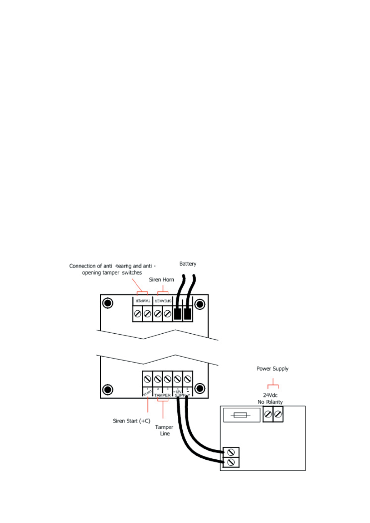
INSTALLAZIONE
- Configurare i jumper J11, J12 e LAUNCHING in funzione della modalità di attivazione della sirena;
- Collegare la batteria tampone da 12 V 2 Ah ai fili rosso e nero con faston;
- Collegare l’alimentazione esterna da 24 V ai morsetti “24 Vdc no polarity” (la polarità non è importante);
- Collegare la linea “positivo a mancare/dare” o “negativo a mancare/dare” al morsetto START;
- I contatti antiapertura e antistrappo sono collegati in serie e devono essere connessi al relativo circuito
della centrale di allarme attraverso i contatti TAMPER;
- Regolare il trimmer per la temporizzazione del suono e lampeggio desiderati;
- Chiudere il contro-coperchio in metallo con le apposite viti;
- Chiudere la sirena con il coperchio in plastica.
SR135 FIRE 24V

www.amcelettronica.com
The SR135 FIRE 24 V is a high-power back-up battery sounder (105 dB at 3 m) protected against tampering
(opening, tearing off). It features a 10 W flasher and a sound/flash timer, variable with adjustable trimmer from
1 min. to 7 min., which trips in case of prolonged alarm (e.g.. connection cable cutting). It has a first switch-on
stop function to prevent the sounder from tripping during installation (for enabling the sounder for normal use
it is necessary to activate/deactivate alarm start).
ADJUSTMENTS AND CONNECTIONS
Rated power voltage: 24 Vdc
Operating limit voltages: 20 ÷ 25 Vdc
Amp draw at max power: 1.5 A
Amp draw when not operating: 2.5 mA
Sound pressure (at Vn=12VDC): 110 dB (A) at 3 m
Light power: 10W
Sound and flash timer: from 1 min to 7 min ± 20%
Buffer battery: 12 Vdc , 2 Ah
Dimensions: 236 mm (L) x 280 mm (H) x 99 mm (P)
Weight (with battery): 2700 g
Operating temperature: - 25 °C ÷ + 55 °C
Flashing short-circuit protection fuse: 2 A
TECHNICAL SPECIFICATIONS
Trimmer TR1 : sound and flashing timer adjustment from 1’ to 7’ ± 20%
TAMPER terminals : N.C. contact for opening and rip-off
SUPPLY terminals : 24 VDC power supply ( rated )
START terminal :
“positive missing” Jumper J11= open
Jumper J12= jumper on B
Jumper LAUNCHING = female jumper on OFF
“negative missing” Jumper J11= closed
Jumper J12= jumper on A
Jumper LAUNCHING = jumper on OFF
“Start with positive” Jumper J11= open
Jumper J12= jumper on A
Jumper LAUNCHING = jumper on OFF
Connect a 10 Kohm resistor between terminal “START” and terminal “-12 V”
“Start with negative” Jumper J11= open
Jumper J12= jumper on B
Jumper LAUNCHING = jumper on OFF
Connect a 10 Kohm resistor between terminal “START” and terminal “+12 V”
ENGLISH
- Configure jumpers J11, J12 (leave LAUNCHING=OFF) according to sounder starting mode.
- Connect the 12 Vdc, 2 Ah buffer battery to the red and black wires with faston;
- Connect external 24 Vdc power supply to the terminals “24 Vdc no polarity” (polarity is not important);
- Connect sounder start wire from the alarm panel to the START terminal;
- The anti-opening and anti-tearing contacts must be connected to the relevant circuit of the alarm unit
through the TAMPER contacts;
- Time the trimmer to desired sound and flash;
- Close the metal cover using the provided screws;
- Close the sounder by means of the plastic cover.
INSTALLATION

www.amcelettronica.com
Sirène extérieure auto-alimentée
Auto-protection et à l’ouverture à l’arrachement
Durée du flash et du son réglable de 1’ à 7’
CONFIGURATION
COMMANDE PAR + DE BLOCAGE
J 11 OUVERT
J 12 SUR B
LAUNCHING SUR OFF
COMMANDE PAR - DE BLOCCAGE
J 11 FERME
J 12 SUR A
LAUNCHING SUR OFF
Dans le cas d’une utilisation avec la commande à apparition de tension ne pas connecter la batterie
sur les bornes + et - 12 v
t 1 + potentiometre de reglage du temps de travail de 1 à 7 mn
Tourner T1 dans le sens des aiguilles d’une montre pour augmenter le temps de travail
CARACTÉRISTIQUES TECHNIQUES
Alimentation : 24 Vcc Puissance sonore (aVn=24 Vcc) : 110 dB (A) à 3 m
Alimentation limite de fonctionnement : 20 +/- 25 Vcc Puissance lumineuse : 10 W
Consommation maxi en fonctionnement : 1,5 A Batterie en tampon : 2 Ah
Consommation en veille : 2.5 mA
Dimensions mm : L 236 x H 280 x P 99
FRANÇAIS

www.amcelettronica.com
Temporizzata Antistrappo
Antiapertura
Anti-schiuma Anti-perfora-
zione
Memoria
d’allarme
Controllo
batteria
LED stato
IMQ II° IMQ III°Timed Anti-opening
Anti-tearing
Anti-foam Anti-drill Alarm
memory
Battery test Status LED
Temporisée A.P. Anti-mousse Anti-perfora-
tion
Memorie
d’alarme
Teste bat-
terie
LED d’etate
SR135 ••
SR137 ••• •
SR139 ••••••
•
SR135 FIRE ••
SR135/L •• • •
SR120/I ••
PZ2
Tutti i ns. prodotti sono conformi ai requisiti richiesti dalla norma CEI 79-2 2° ed. 1993.
L’installazione deve essere eseguita a regola d’arte da personale specializzato.
AMC Elettronica S.r.l. declina ogni responsabilità nel caso in cui il prodotto venga manomesso da persone
non autorizzate.
Si raccomanda di verificare il corretto funzionamento del sistema d’allarme almeno una volta al mese, tut-
tavia un sistema di allarme elettronico affidabile non evita intrusioni, rapine, incendi o altro, ma si limita a
diminuire il rischio che tali situazioni si verifichino.
Gli avvisatori telefonici in tecnologia GSM senza l’utilizzo di linee telefoniche PSTN, non possono essere
garantiti in caso di limitazione e/o problematiche dovute a difettosità nel servizio offerto dal gestore di
rete.
Our products/systems comply with the essential requirements of EEC directives. Installation must be car-
ried out following the local installation norms by qualified personnel.
AMC Elettronica S.r.l. refuses any responsibility when changes or unauthorized repairs are made to the pro-
duct/system. It is recommended to test the operation of the alarm product/system at least once a month.
Despite frequent testing and due to, but not limited to, any or all of the following: tampering, electrical or
communication disruption or improper use, it is possible for the product/system to fail to prevent burglary,
robbery, fire or otherwise. A properly installed and maintained alarm system can only reduce the risk that
this happens.
Any GSM speech dialler or communicator, not connected to the PSTN standard telephone line, does not
ensure proper communication in case of problems or limitations due to the GSM network.
Tous nos produits sont conformes aux directives CE
L’installation doit ètre effectuée dans les règles de l’art par un installateur qualifié. AMC Elettronica S.r.l.
décline toute responsabilité en cas d’utilisation des produits par des personnes non habilitées. Il est
recommandé de vérifier le bon fonctionnement du système d’alarme au moins une fois par mois. Un sy-
stème d’alarme électronique n’exclut pas le risque d’intrusion, de vol, d’incendie mais limite et diminue
fortement celui-ci.
Les transmetteurs intégrant une technologie GSM, en secours ou pas d’une ligne PSTN, ne peuvent ètre
garantis en cas de limitation ou de problème du à l’opérateur téléphonique ou au rèseau GSM.
Table of contents
Languages:
Other AMC Marine Equipment manuals
Popular Marine Equipment manuals by other brands

Francis Searchlights
Francis Searchlights LED480 Remote Control User instruction & installation manual

Clarion
Clarion CMS20 Owner's manual & installation manual

E2S
E2S Minialert IS-mC1 instruction manual

Young
Young 06206 manual

KVH Industries
KVH Industries TracVision R6 DX Replacement instructions

Bennett Marine
Bennett Marine AUTO TAB CONTROL Owner's Manual & Installation Instructions