E2S BExDTS110D User manual

__________________________________________________________________________________________________________________________________
EuropeanSafetySystemsLtd. Impress House, MansellRoad, Acton, LondonW37QHsales@e-2-s.com Tel: +44(0)208 743 8880
www.e-2-s.com Fax: +44(0)208 740 4200
DocumentNo. IS2457-PIssue E12-03-10Sheet1of 4
INSTRUCTION MANUAL(ATEX/IECEx)
BExDTS110DFlameproofSontel
ForuseinFlammableGasandDustAtmospheres
1)Introduction
The BExDTS110Dis aflameproofSonteltelephonesounder
whichiscertifiedtomeettherequirementsoftheATEX
directive 94/9/ECandIECExscheme.The Sontelproduces a
loudaudible signal when triggeredby atelephoneringing
signal andcanbeused in hazardous areaswhere potentially
flammablegas and dustatmospheresmay be present. Thirty-
two differentsounds can be selected by internalswitches(see
tone tableonPage 4).TheBExDTS110Dunitproduces
output levelsin the110dB(A)range.Theunitcanbeused in
Zone1 andZone2 areas withgases ingroups IIA,IIBand IIC
and temperature ClassificationsofT1, T2, T3 andT4. For
ambient temperaturesover +55ºCthegasgroupsare limited to
IIAand IIB.They canalso beused inZone21 and Zone 22
areas for combustible dusts and have anIP rating of IP67 and
asurfacetemperaturerating ofT100ºCup to+55ºCand
T115ºC over +55ºC.
2)Marking
All unitshavearating label, whichcarriesthe following
important information:-
UnitType No. BExDTS110D
Input Voltage: DC Units: 12V or 24Vor 48V
AC Units: 230Vor 110Vor 115V
Codes:ExdIICT4forTa–50°Cto+55°C
ExdIIBT4forTa–50°Cto+70°C
ExtDA21IP67 T115°CbasedonmaxTaof +70°C
CertificateNo’s KEMA99ATEX6312
IECExKEM10.0003
“Warnings” DONOTOPENWHENANEXPLOSIVE
GASORDUSTATMOSPHEREISPRESENT
COVERBOLTSCLASS A4-80
USE HEATRESISTINGCABLES ANDCABLEGLANDS
(Rated 110ºC)ATAMB. TEMPERATURES OVER40ºC
Year of Construction/
Serial No. i.e. 10 / 1DTS23000001
3) TypeApprovalStandards
The SontelhasECType Examinationand IECExcertificates
issuedbyKEMAandhasbeenapprovedtothe following
standards:-
EN60079-0:2006 IEC60079-0:2004(Ed4) GeneralRequirements
EN60079-1:2007 IEC60079-1:2007 (Ed6) Flameproof Enclosure‘d’
EN61241-0:2006 IEC61241-0:2004(Ed1)DustGeneral
Requirements
EN61241-1:2004 IEC60079-1:2004(Ed1)DustEnclosurestD
4) InstallationRequirements
The Sontels mustbeinstalledinaccordance with thelatest
issues oftherelevantpartsof the EN60079 standards orthe
equivalent IECstandards –Selection,Installationand
maintenanceof electrical apparatusforuse in potentially
explosiveatmospheres(other thanminingapplicationsor
explosiveprocessing and manufacture):-
EN60079-14:2008 ElectricalInstallationsinHazardous
IEC60079-14:2007(Ed4) Areas(otherthan mines)
EN60079-10:2003 Classificationof HazardousAreas
IEC60079-10:2008(Ed1)
The installationof theunitsmustalsobe in accordance with
anylocal codesthat may apply and should onlybe carried out
byacompetentelectricalengineerwhohasthenecessary
training.
5) Zones,GasGroup,Category,IPRating and
TemperatureClassification
The BExDTS110D Sontels have been certified Exd IICT4 for
Ta –50°C to +55ºC and Ex d IIB T4 forTa –50°C to +70ºCfor
gas and ExtDA21 IP67 T115ºC basedonmax. Taof+70ºC
fordust.Thismeansthat the units can be installed inlocations
with the following conditions:-
AreaClassification Gas:
Zone 1
Explosivegasair mixturelikely tooccurin
normal operation.
Zone 2
Explosivegasair mixturenot likely to occur,
andifitdoes, it willonly exist for a short time.
GasGroupings:
GroupIIA
Propane
GroupIIB
Ethylene
GroupIIC
(Upto
+55ºConly)
Hydrogen andAcetylene
TemperatureClassification:
T1
400
o
C
T2
300
o
C
T3
200
o
C
T4
135
o
C
0518
II
2G
/D
Epsilonx:
Equipment Groupand
Category:
CE Marking
NotifiedBody No.

__________________________________________________________________________________________________________________________________
EuropeanSafetySystemsLtd. Impress House, MansellRoad, Acton, LondonW37QHsales@e-2-s.com Tel: +44(0)208743 8880
www.e-2-s.com Fax: +44(0)2087404200
DocumentNo. IS2457-PIssue E12-03-10 Sheet2of 4
AreaClassification Dust:
Zone 21
Explosive dust airmixturelikely to occur in
normal operation.
Zone 22
Explosive dust air mixturenotlikelytooccur,
andif it does, it will onlyexist fora short time.
IPRating: IP67 T100ºC Ta< +55ºC
T115ºC Ta< +70ºC
EquipmentCategory: 2G/D
Ambient Temperature Range:
-50°C to+55°CGasGroupsIIA, IIB andIIC
-50°C to+70°CGasGroup IIAandIIB
6) SontelLocation and Mounting
The locationof the Sontelsshould be madewithdue regardto
the area over whichthewarningsignalmustbeaudible. And
they shouldonlybe fixedto services that cancarry the weight
of theunit.
The Sontels shouldbesecurely boltedtoasuitablesurface
usingthe7mmdiameter boltholesinthe stainlesssteelU
shapedmounting bracket(see figure1). The anglecan then be
adjusted in the directionthat the sound is primarily required to
cover. Thiscan beachieved by looseningthetwolarge bracket
screwsin the side of theunit, which allow adjustment in steps
of18°.Oncompletion of the installation thetwo largebracket
adjustment screws onthe sideof theunit must befully
tightenedto ensurethat theunit cannotmovein service.
7) AccesstotheFlameproofEnclosure
Inorder to connect theelectrical supply cableandthe
telephonelinecabletothe Sontel it isnecessarytoremovethe
flameproof covertogain accessto theflameproofchamber.
Toachieve this remove thefourM6 hexagon sockethead
screws(see figure2)and withdraw theflameproofcovertaking
extremecarenotto damagetheflameproof jointsinthe
process.
Notethefour M6screwsareClass A4-80stainless steel
and onlyscrewsof thiscategorycanbeusedon these
Sontels. Itis thereforeimportant that thesescrews and their
springwashersarekept ina safe place duringinstallation.
Oncompletionof thecable wiring installationtheflameproof
jointsshould be inspectedto ensurethat theyarecleanand
thatthey havenotbeen damagedduringinstallation.Also
checkthat theearthbonding wirebetween thetwocasting
sectionsissecureandthe‘O’ringseal isinplace.When
replacingtheflameproof cover castingensurethat itis square
withthe flameproof chamber castingbefore inserting. Carefully
push thecoverin placeallowing timefor theair to be expelled.
Only afterthecover is fullyin placeshould the fourM6
StainlessSteelA4-80 coverboltsand theirspringwasherbe
insertedand tighteneddown. If the coverjamswhile it isbeing
inserted, carefully remove it andtry again.Never use thecover
boltsto force the cover intoposition.
8) PowerSupplySelection
Itis important that asuitable powersupplyisused torunthe
Sontels.
The followingtableshowstheinputcurrent taken by the
various units:-
UnitType InputInput Max.
VoltageCurrentI/PVolts
BExDTS110D 24VDC 265mA 30V
BExDTS110D 12VDC 195mA 15V
BExDTS110D 48VDC 130mA 58V
BExDTS110D 230VAC56mA 264V
BExDTS110D 110VAC93mA 121V
BExDTS110D 115VAC110mA 126V
The input currentwillvaryaccordingtothe voltage inputlevel
and the frequencyofthetoneselected.The current levels
shown abovearefor the 440Hz Continuoustone@nominal
input voltage.Theunitshaveaswitching voltageregulator
circuit andthereforethe input current levelwill decrease
slightly astheinputvoltagein increasedand willincrease
slightly astheinput voltageisreduced.
The abovetable also showsthemaximum voltages at which
the sontelscan beoperated.
Figure 1
PlasticAcousticHorn
(Anti-staticPlastic)
Flameproof
Chamber
Flameproof
Cover
S/SMounting
Bracket
Figure
2
4off M6CoverScrews
ExternalEarth
Terminal

__________________________________________________________________________________________________________________________________
EuropeanSafetySystemsLtd. Impress House, MansellRoad, Acton, LondonW37QHsales@e-2-s.com Tel: +44(0)208743 8880
www.e-2-s.com Fax: +44(0)2087404200
DocumentNo. IS2457-PIssue E12-03-10 Sheet3of 4
9) CableSelection
Whenselecting the cable size consideration mustbegivento
the inputcurrentthateach unit draws(seetable above), and
the length ofthe cableruns.
SAFETY WARNING: If the high outputBExDTS110D units are
used athighambienttemperatures,i.e. over+40ºC, then the
cable entrytemperature mayexceed +70ºCand therefore
suitable heat resistingcablesmustbeused, witharated
service temperatureofat least 110ºC.
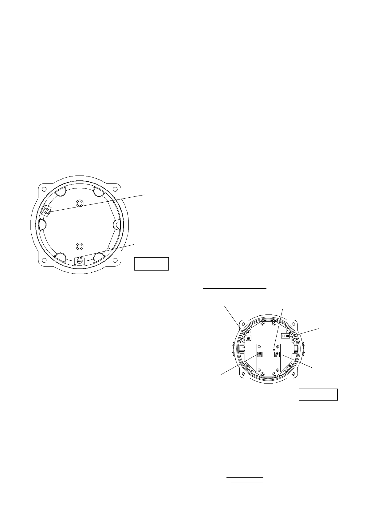
10) Earthing
The Sontelunits mustbeconnectedtoagood quality earth.
The unitsareprovidedwithinternal and externalearthing
terminalswhichare bothlocatedonthe terminalchamber
sectionoftheunit (seefigures 2and3).
Whenusingtheinternal earth terminalensure thatthe
stainlesssteelM4flat washer isbetweentheincoming earth
wireand the enclosure.
Whenusingtheinternal earth terminalensure thatthe
stainlesssteelM4flat washer isbetweentheincoming earth
wireand the enclosure.
When using theexternal earthterminal a cablecrimp lugmust
be used. Thecablelugshould be locatedbetween thetwoM5
stainlesssteelflat washers. TheM5stainlesssteel spring
washermust be fixed betweenthe outer flatwasher andthe
M5 stainless steel nut toensurethatthe cablelugissecured
againstlooseningand twisting.
The internalearthbondingwireensures that agoodquality
earth is maintained betweentheflameproofchambercasting
and the flameproofcovercasting.
11) CableGlands
The BExDTS110DSontelshave dual cableglandentries
whichhave an M20x1.5asstandard.Onlycable glands
approvedfor Ex‘d’applicationscan beused,which mustbe
suitable forthetype ofcablebeingusedand alsomeetthe
requirementsofthe Ex‘d’flameproof installationstandard
EN60079-14:2008/ IEC60079-14:2007.
Whenonly one cable entry isusedtheotherone mustbe
closed with an Ex ‘d’flameproofblankingplug,which mustbe
suitablyapprovedfortheinstallation requirements.
For combustibledust applications, the cableentry deviceand
blanking elementsshall be in type of explosionprotection
increasedsafety"e"or flameproof enclosure "d"andshall have
an IP 6Xratingaccording toEN 60529.
SAFETY WARNING: IftheBExDTS110D Sontelsareusedat
high ambienttemperatures,i.e.over+40ºC,thenthecable
entry temperaturemay exceed+70ºCand thereforesuitable
heatresisting cable glands mustbe used,with arated service
temperature of at least 110ºC.
12) CableConnections
The cableconnectionsaremadeinto theterminal blockson
the Sontelpcbassemblylocated in theflameproof enclosure.
Seesection7ofthismanualfor access totheflameproof
enclosure.Theprintedcircuitboardhastwoterminal blocks;
one for thepowersupply inputvoltageand onefor the
telephone signalinputcable(seefigures 4and 5). The power
input cableshouldenterthe enclosurevia oneofthe M20
cable entries and be connected to thesupply terminals (L and
N) AC units (+ve and –ve) DCunitsandthetelephonesignal
cable should entertheenclosure via theotherM20entryand
be connectedtothetelephone terminal.
A singlewire withacross sectionalarea ofup to 4mm² can be
connectedtoeachterminal way. Whenconnecting wires to the
terminalsgreat care should betakento dressthewire so that
whenthecoverisinsertedintothechamberthewires donot
exert excesspressureonthe terminalblocks. Thisis
particularlyimportantwhenusingcableswithlarge cross
sectional areassuchas2.5mm² andabove.
Figure 4
BEx
D
TS110D
AC
Sontel
s
DIPSwitch
VolumeControl
TelephoneSignal
Input Terminals
MainsSupply
Input Terminals
Land N
PulseTone
HeaderPin
2off M20
CableEntries
InternalEarthTerminal
Figure3
InternalBonding
WireTerminal

__________________________________________________________________________________________________________________________________
EuropeanSafetySystemsLtd. Impress House, MansellRoad, Acton, LondonW37QHsales@e-2-s.com Tel: +44(0)208743 8880
www.e-2-s.com Fax: +44(0)2087404200
DocumentNo. IS2457-PIssue E12-03-10 Sheet4of 4
13) ToneSelection
The BExDTS110D Sontels have 32 differenttones that can be
selected bytheDIPswitchesonthe sounderpcb(seefigures
4and5). Thetone tableon page four showstheswitch
positionsforthe32tones.
14) PulseToneOperation
The BExDTS110DSontelhastwo modes ofoperation
continuoustone operationandpulsedtoneoperation. To
selectcontinuoustoneoperationthepulse toneheader pins
should notbeshorted(seefigures 4 and5). Inthis modethe
output tone will beas per the tone table.To select pulse tone
operation thepulsetone headerpinsshouldbeshorted (see
figures4and5).Inthismodeof operationthe selected tone
pattern willpulseon andofffollowingthetelephone input
signal. Note if pulsedtone operationis selected it is advisable
nottoselectanyof theintermittenttones, such astone11.
15) VolumeControl
The BExDTS110DSontel hasavolumecontrol toadjustthe
output level. To setthe requiredoutputlevel, adjust the
potentiometeronthe sontelpcb (see figure4).Formaximum
output level the potentiometershouldbeset tothe fully
clockwise position.
TONESELECTIONTABLE
NoteSwitchNo. 6isnotused
ToneSelection
DIPSwitch
Settings
Stage1
FrequencyDescription
12345
1
Continuous1000Hz
Toxicgasalarm
00000
2
Alte
rnating800/1000Hzat0.25s
intervals
10000
3
SlowWhoop 500/1200Hzat0.3Hz
with0.5sgaprepeated
01000
4
Sweeping 800/1000 at1Hz
11000
5
Continuousat2400Hz
00100
6
Sweeping 2400/2900Hzat7Hz
1
0100
7
Sweeping 2400/2900Hzat1Hz
01100
8
Siren500/1200/500Hzat0.3Hz
11100
9
Sawtooth1200/500Hzat1Hz
00010
10
Alternating2400/2900Hzat2Hz
10010
11
Intermittent1000Hzat0.5Hz
Generalalarm
01010
12
Alternating800/1000Hzat0.875Hz
11010
13
Intermittent2400Hzat1Hz
00110
14
Intermittent800Hz0.25son 1soff
10110
15
Continuousat800Hz
01110
16
Intermittent
660Hz150mSon,
150mSoff
11110
17
Alternating544Hz
(100mS)/440Hz(400mS)
00001
18
Intermittent660Hz1.8son, 1.8soff
10001
19
1400Hzto1600Hzsweepupover
1s-1600Hzto1400Hzsweepdown
over0.5s
01
001
20
Continuous660Hz
11001
21
Alternating554/440Hzat1Hz
00101
22
Intermittent554Hzat0.875Hz
10101
23
800Hzpulsingat2Hz
01101
24
Sweeping 800/1000Hzat50Hz
11101
25
Sweeping 2400/2900Hzat50Hz
00011
26
Simulatedbell sound
10011
27
Continuous554Hz
01011
28
Continuous440Hz
11011
29
Sweeping 800/1000Hzat7Hz
00111
30
420Hzrepeating0.625son, 0.6
25s
offAustralianalertsignal
10111
31
1200/500Hzat1Hz
Preparetoabandonplatform
01111
32
Sweeping 500/1200Hz3.75son,
0.25soff 15Hz
11111
BEx
D
TS110D DCSontels
DCPowerSupply
Input Terminals
+veand-ve
Telephone Signal
InputTerminals
Terminal
block
not used
DIPSwitch
VolumeControl
PulseTone
HeaderPin
Figure 5

EC DECLARATION OF CONFORMITY
Manufacturer: European Safety Systems Ltd.
Impress House, Mansell Road, Acton
London, W3 7QH, UK
Telephone: +44 (0)20 8743 8880 European Safety Systems Ltd
Facsimile: +44 (0)20 8740 4200 Company Registration No. 2763350
E-mail: sales@e2s.com Registered Office: Impress House
www.e2s.com Mansell Road, London, UK, W3 7QH, UK
Equipment Type: BExS110D, BExS120D, BExS110E, BExS120E,
BExDS120D, BExDS110D, BExDS120E, BExDS110E,
BExL25D, BExL15D, BExL25E, BExL15E,
BExDL25D, BExDL15D, BExDL25E, BExDL15E,
BExA110D, BExA120D, BExA110E, BExA120E,
BExDA110D, BExDA120D, BExDA110E, BExDA120E,
BExTS110D, BExDTS110D, BExH120D, BExDH120D, BExL25GD, BExDL25GD
Directive 94/9/EC: Electrical and Mechanical equipment for use in explosive atmospheres (ATEX)
Notified
Body for EC type Examination:
KEMA Quality B.V.
Notified Body No.: 0344
Utrechtseweg 310, 6812 AR Arnhem, The Netherlands
EC
-
type Examination Certificate:
KEMA 99ATEX6312
Notified Body for Quality Assurance Notification:
Sira Certification Service
Notified Body No.: 0518
Rake Lane, Eccleston, Chester CH4 9JN, UK
Quality Assur
ance Notification
:
SIRA 05 ATEX M342
Provisions fulfilled by the equipment:
ll2 G Ex d llB or llC T4 or
ll2 G Ex de llB or llC T4
ll2 D Ex tD A21 lP66 or lP67 T100 °C or T115 °C
Standards applied:
EN 60079-0:2006
EN 60079-1:2007
EN 60079-7:2003
EN 61241-0:2006
EN 61241-1:2004
Directive 89/106/EEC: Construction Products Directive (CPD) – BExS110D24DC / BExS120D24DC (tones 2, 3, 9, 15, 16, 17) only
Notified Body for EC type Examination:
VdS Schadensverhütung GmbH
Notified Body No.: 0786
Amsterdamer Str 172-174, 50735 Köln, Germany
EC
-
type Examination Certificate:
0708-CPD-20225
Standards applied:
EN 54-3:2001 + A1:2002
Directive 2009/26/EC: Marine Equipment Directive (MED) – BExS110D24DC-M only
Notified Body for EC type Examination:
Germanischer Lloyd SE
Notified Body No.: 0098
Brooktorkai 18, 20457 Hamburg, Germany
EC
-
type Examination Certificate:
19 702 - 11 HH
Standards applied:
EN 54-3:2001 + A1:2002 + A2:2006
IEC 60092-504: 2001
IEC 60533: 1999
Directive 2004/108/EC: Electromagnetic Compatibility Directive (EMC)
Standards applied:
EN 61000-6-1:2007
EN 61000-6-2:2005
EN 61000-6-3:2007
EN 61000-6-4:2007
The standards EN 60079-0: 2006, EN 60079-7:2003, EN 61241-0:2006 and EN 61241-1:2004 are no longer harmonized. The
requirements of these standards have been checked against the harmonized standards EN 60079-0:2009, EN 60079-7:2007 and EN
60079-31:2009 and there were no major technical changes affecting the latest technical knowledge for the products listed above.
On behalf of European Safety Systems Ltd., I declare that, on the date the equipment accompanied by this declaration is placed on the
market, the equipment conforms with all technical and regulatory requirements of the above listed directives.
Martin Streetz Date and Place of Issue: London, 04/07/2012
Quality Assurance Manager Document No: DC-001-Issue_C
Table of contents
Other E2S Marine Equipment manuals

E2S
E2S BExA120D User manual

E2S
E2S BE DCS110-05D Series User manual

E2S
E2S E2xS1RDC024 Manual

E2S
E2S STExS1 User manual

E2S
E2S E2 S2R Series User manual

E2S
E2S D1xS2 Series User manual

E2S
E2S BExCS110-05D-P User manual

E2S
E2S BExCS110-05D-P User manual

E2S
E2S E2XS112UL User manual

E2S
E2S BExS110D-R User manual
Popular Marine Equipment manuals by other brands

Edgetech
Edgetech Port Pop-Up USER HARDWARE MANUAL

Qlight
Qlight QWCD35T manual

Seastar Solutions
Seastar Solutions SeaWays Installation instructions and user manual

Simrad
Simrad GN70 Operator and installation manual

Jensen
Jensen MCD5112 - Radio / CD Player owner's manual

Furuno
Furuno FCV-271 Operator's manual