Beijer Electronics BoX2 extreme User manual

Installation Manual
BoX2 base
MAEN274
2023-09

Foreword
All BoX2 devices are developed to satisfy the demands of human-machine communication.
Configuration is carried out on a PC using iX Developer software. The project can then be transferred
and stored in the device itself. Various types of automation equipment such as PLCs, servos or
drives can be connected to the device. In this manual, the term “the controller” refers to the
connected equipment. This manual explains how to install the device. Please refer to the iX
Developer reference manual for further information.
Copyright © 2023 Beijer Electronics AB. All rights reserved.
The information in this document is subject to change without notice and is provided as availa-
ble at the time of printing. Beijer Electronics AB, including all its group companies, reserves
the right to change any information without updating this publication. Beijer Electronics AB, in-
cluding all its group companies, assumes no responsibility for any errors that may appear in this
document. Read the entire installation manual prior to installing and using this equipment. Only
qualified personnel may install, operate or repair this equipment. Beijer Electronics AB, includ-
ing all its group companies, are not responsible for modified, altered or renovated equipment.
Because the equipment has a wide range of applications, users must acquire the appropriate
knowledge to use the equipment properly in their specific applications. Persons responsible
for the application and the equipment must themselves ensure that each application is in
compliance with all relevant requirements, standards and legislation in respect to configuration
and safety. Only parts and accessories manufactured according to specifications set by Beijer
Electronics AB, including all its group companies, may be used.
BEIJER ELECTRONICS AB, INCLUDING ALL ITS GROUP COMPANIES, SHALL NOT BE LIABLE TO
ANYONE FOR ANY DIRECT, INDIRECT, SPECIAL, INCIDENTAL OR CONSEQUENTIAL DAMAGES RESULT-
ING FROM THE INSTALLATION, USE OR REPAIR OF THIS EQUIPMENT, WHETHER ARISING IN TORT,
CONTRACT, OR OTHERWISE. BUYER'S SOLE REMEDY SHALL BE THE REPAIR, REPLACEMENT, OR
REFUND OF PURCHASE PRICE, AND THE CHOICE OF THE APPLICABLE REMEDY SHALL BE AT THE
SOLE DISCRETION OF BEIJER ELECTRONICS AB, INCLUDING ALL ITS GROUP COMPANIES.
Head Office
Beijer Electronics AB
Box 426
201 24 Malmö, Sweden
www.beijerelectronics.com / +46 40 358600

Table of Contents
1. Safety Precautions ........................................................................................ 5
1.1. General ............................................................................................ 5
1.2. Hazardous Materials ............................................................................. 5
1.3. Disposal Requirements Under WEEE Regulations ............................................ 5
1.4. UL and cUL Installation .......................................................................... 6
1.5. During Installation ................................................................................ 6
1.6. During Use ......................................................................................... 7
1.7. Service and Maintenance ........................................................................ 7
1.8. Dismantling and Scrapping ...................................................................... 7
2. Installation ................................................................................................. 8
2.1. Installation Process .............................................................................. 8
2.1.1. Connections to the Controller ......................................................... 9
2.1.2. Other Connections and Peripherals ................................................... 9
3. Technical Data ............................................................................................ 10
4. Chemical Resistance ..................................................................................... 12
4.1. Plastic Casing .................................................................................... 12
5. Device Drawings .......................................................................................... 13
5.1. Connectors ....................................................................................... 13
5.1.1. Communication Ports .................................................................. 13
5.2. Device Outline ................................................................................... 14
6. Additional Installation Tips ............................................................................. 15
6.1. Grounding the Device ........................................................................... 15
6.2. Ethernet Connection for the Device .......................................................... 16
6.3. To Achieve Better EMC Protection ............................................................ 16
6.4. Ambient Temperature .......................................................................... 17
6.5. Safety ............................................................................................. 19
6.6. Galvanic Isolation ............................................................................... 20
6.7. Cable and Bus Termination RS-485 ........................................................... 20
6.8. USB Flash Drive .................................................................................. 21
Beijer Electronics, MAEN274 3 2023-09

4

1. Safety Precautions
Both the installer and users of the BoX2 device must read and understand this manual.
1.1. General
• Read the safety precautions carefully.
• Check the delivery for transportation damage. If damage is found, notify the supplier as soon as
possible.
• Do not use the device in an environment with high explosive hazards.
• The supplier is not responsible for modified, altered, or reconstructed equipment.
• Use only parts and accessories manufactured according to specifications of the supplier.
• Read the installation and operating instructions carefully before installing, using, or repairing the
device.
• Never allow fluids, metal filings or wiring debris to enter any openings in the device. This may
cause fire or electrical shock.
• Only qualified personnel may operate the device.
• This is an OPEN-TYPE device and should therefore be installed in an enclosure to prevent
unqualified personnel from operating it.
• The figures in this manual serve an illustrative purpose. Because of the many variables associated
with any particular installation, the supplier cannot assume responsibility for actual use based on
the figures.
• The supplier neither guarantees that the device is suitable for your particular application, nor
assumes responsibility for your product design, installation or operation.
1.2. Hazardous Materials
Part description
零件描述
Toxic and hazardous materials or elements
有毒和有害的材料或元素
PCB and electronic components
PCB 和电子元件
Pb Hg Cd Cr6+ PBB PBDE
X O O O O O
O: Indicates that the concentration of the hazardous substance in all homogeneous materials in the
parts is below the relevant threshold of the GB/T 26572-2011 standard.
O: 表示该有害物质在该部件所有均质材料中的含量均在 GB/T 26572-2011 规定的限 量要求以下。
X: Indicates that the concentration of the hazardous substance of at least one of all homogeneous
materials in the parts is above the relevant threshold of the GB/T 26572-2011 standard. But still
complies with the EU RoHS Directive 2011/65/EU.
X: 表明该有害物质至少在部件的某一均质材料中的含量超出 GB/T 26572-2011 规定 的限量要求。但仍然
符合 EU RoHS 指令 2011/65/EU。
1.3. Disposal Requirements Under WEEE Regulations
For professional users in the European Union: If you wish to discard electrical and electronic
equipment (EEE), please contact your dealer or supplier for further information.
For disposal in countries outside of the European Union: If you wish to discard this product please
contact your local authorities or dealer and ask for the correct method of disposal.
Safety Precautions
Beijer Electronics, MAEN274 5 2023-09
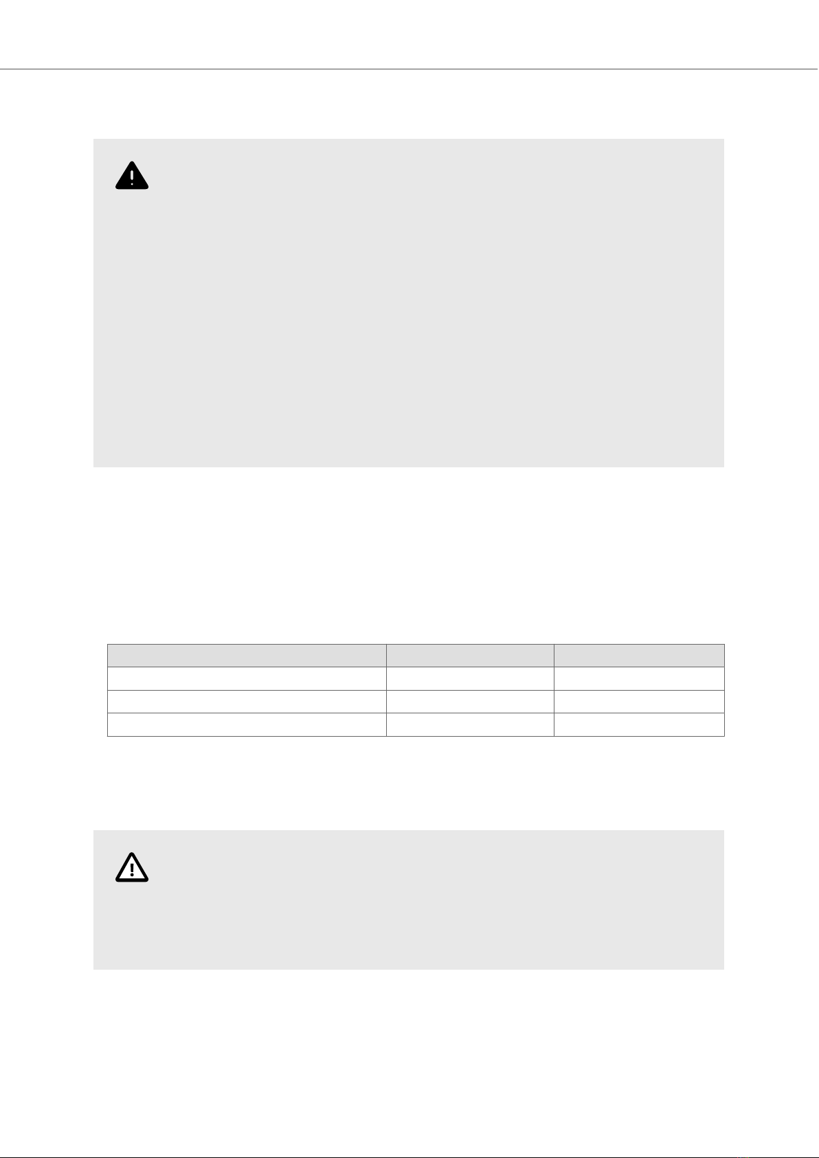
1.4. UL and cUL Installation
WARNING
• Only UL and cUL approved expansion units are allowed to be connected to the
port designated “EXPANSION”. At the moment there are no such units evaluated or
allowed.
SEULES LES UNITÉS D'EXTENSION CERTIFIÉES UL ET cUL PEUVENT ÊTRE RACCORDÉES
AU PORT DÉSIGNÉ «EXPANSION». À L'HEURE ACTUELLE, AUCUNE UNITÉ DE CE TYPE
N'A ÉTÉ TESTÉE OU AUTORISÉE.
• Explosion hazard! Substitution of components may impair suitability for Class I,
Division 2.
RISQUE D’EXPLOSION! LA SUBSTITUTION DE COMPOSANTS PEUT NUIRE Á LA
CONFORMITÉ DE CLASSE I, DIVISION 2.
• Battery may explode if mistreated. Do not recharge, disassemble or dispose of in
fire.
LA BATTERIE PEUT EXPLOSER EN CAS DE MAUVAISE MANIPULATION. NE LA
RECHARGEZ PAS, NE LA DÉMONTEZ PAS ET NE LA JETEZ PAS DANS LE FEU.
• This product contains a battery; this must only be changed in an area known to be non-hazardous.
• Replace the battery with a BR2032 battery. Use of another type of battery may present a risk of
fire or explosion.
• For use on a flat surface of a type 4X enclosure indoor use only.
• Use minimum 75°C copper conductors only.
• To make wiring connections to the power supply connector, follow the table with cable and torque
specifications below:
Terminal Block Connector Wire Size AWG Torque (Lb.In.)
X1/X100 Phoenix connectors AWG 30 – 12 5 – 7
X1/X100 Anytek connectors AWG 24 – 12 3.5
X1/X100 DECA connectors AWG 24 – 12 7
• These devices are Class 2 supplied programmable controllers (industrial PCs) for the use in
industrial control equipment and are intended to be (front) panel mounted (Type 12 and 4x for
indoor use only).
CAUTION
The enclosure provides a degree of protection of at least IP20, but when installed in
an apparatus, it should meet IP65.
LE BOÎTIER OFFRE UN DEGRÉ DE PROTECTION D'AU MOINS IP20, MAIS LORSQU'IL EST
INSTALLÉ DANS UN APPAREIL, IL DOIT ÊTRE DE CLASSE IP65.
1.5. During Installation
• Install the device according to the accompanying installation instructions.
• Ground the device according to the accompanying installation instructions.
Safety Precautions
2023-09 6 Beijer Electronics, MAEN274

• Only qualified personnel may install the device.
• Separate the high voltage, signal, and supply cables.
• Make sure that the voltage and polarity of the power source is correct before connecting the
device to the power outlet.
• Peripheral equipment must be appropriate for the application and location.
1.6. During Use
• Keep the device clean.
• Emergency stop and other safety functions may not be controlled from the device.
1.7. Service and Maintenance
• Only qualified personnel should carry out repairs.
• The agreed warranty applies.
• Before carrying out any cleaning or maintenance operations, disconnect the equipment from the
electrical supply.
• The battery must be replaced by an authorized Beijer Electronics service center.
1.8. Dismantling and Scrapping
• Recycle the device and parts of it according to local regulations.
• The following components contain substances that might be hazardous to health and the
environment: lithium battery and electrolytic capacitor.
Safety Precautions
Beijer Electronics, MAEN274 7 2023-09

2. Installation
2.1. Installation Process
The BoX2 device can be used as a bench top device or clipped onto a DIN rail.
The following is needed:
• No tools required - standard usage.
Do the following:
1. Unpack and check the delivery. If damage is found, notify the supplier.
NOTE
Place the device on a stable surface during installation. Dropping the device or
letting it fall may cause damage.
2. Connect the cables in the specified order, according to the following drawing and steps.
Installation
2023-09 8 Beijer Electronics, MAEN274
24V DC
RS232/
RS422/
RS485
24V DC
A
D
Controller
Power
B
Ethernet
C
The image is illustrative only and may differ slightly from the actual device.
• Connect cable A.
• Connect cable B, using 14-20 AWG (2.08–0.52 mm2), 180–220 N-cm torque.
• Connect cable C.
• Connect cable D. The recommended cross-section of the cable is 1.5 mm2.
CAUTION
• The device must be brought to ambient temperature before it is started up. If
condensation forms, ensure that the device is dry before connecting it to the
power outlet.
• Ensure that the device and the controller system have the same electrical
grounding (reference voltage level), otherwise errors in communication may occur.
• Ensure that the voltage and polarity of the power source is correct.
• Separate high voltage cables from signal and supply cables.
• Shielded communication cables are recommended.
2.1.1. Connections to the Controller
For information about the cables to be used when connecting the device to the controller, please
refer to the help file for the driver in question or see section Cables.
2.1.2. Other Connections and Peripherals
Cables, peripheral equipment and accessories must be suitable for the application and its
environment. For further details or recommendations, please refer to the supplier.
Installation
Beijer Electronics, MAEN274 9 2023-09

3. Technical Data
Parameter BoX2 base
Front panel, W×H×D 130 × 89 × 35 mm
Standalone mounting VESA 75 × 75
Note: Maximum screw length for VESA mounting is 4 mm. Usage of
longer screws may lead to damage.
Sealing IP20
Frame material Plastic (PC+ABS)
Weight 0.3 kg
CPU 400 MHz ARM9
Serial port COM A Standard D-sub (9 Pin, female)
COM1: 1×RS-232 Rx/Tx with RTS/CTS
COM2: 1×RS-422 or 1×RS-485 or 1×CAN2.0B
*Not supported for X2 pro 7/10/15web or X2 extreme 7/12/15 HP
web.
Serial port COM B M12 (8 pin, female)
Standard D-sub (9 Pin, female)
COM3: 1×RS-232 Rx/Tx with RTS/CTS
COM4: 1×RS-485
*Not supported for X2 control 7/10/15 web or X2 extreme 7/12/15
HP web.
Ethernet 10/100 Mbit Base-T (shielded RJ45 with LEDs)
USB Supports up to USB 2.0 High Speed
Flash memory
(application memory)
256 MB SSD (NAND Flash)
Application memory 200 MB
Memory RAM 128 MB (DDR2)
NVRAM N/A
Real time clock Yes
Battery Lithium ion, 3V / 200mAh
Power consumption at
rated voltage
3 W
Fuse Internal DC fuse, 2.0 AT
Power supply CE: The power supply must conform with the requirements
according to EN/IEC 60950 and EN/IEC 61558-2-4.
UL and cUL: The power supply must conform with the requirements
for class 2 power supplies.
Operating temperature -10°C to +50°C
Storage temperature -20°C to +60°C
Relative humidity in
operation
5 - 85% non-condensation
Technical Data
2023-09 10 Beijer Electronics, MAEN274

Parameter BoX2 base
Vibration 1g, according to IEC 60068-2-6, Test Fc
Mechanical shock 15g, half-sine, 11ms according to IEC60068-2-27
Approvals and
certifications
CE/FCC/KCC Information is available on www.beijerelectronics.com
UL approval Information is available on www.beijerelectronics.com and UL.com
Technical Data
Beijer Electronics, MAEN274 11 2023-09

4. Chemical Resistance
4.1. Plastic Casing
The frame and casing material is plastic (PC+ABS). This material withstands exposure to the following
chemicals without visible change:
Acetic acid 10% Nitric acid 10%
Baysilon®M300 Phosphoric acid 30%
Citric acid 10% Seawater
Cleaning agent, Dor® Sodium hypochlorite
Curd soap solution 2% Sodium thiosulphate
Hydrochloric acid 20% Sulphuric acid 30%
Hydrogen superoxide 30% Urea
Lactic acid 10%
The material shows limited resistance to the following chemicals at room temperature:
Cleaner’s naphtha, free from aromatic hydrocarbons Heating oil
Ethyl alcohol 96% Isopropanol
Glycerin N-hexane
Glycol Persil powder in solution
The material shows little or no resistance to the following chemicals at room temperature:
Acetone Methylisobutyl ketone
Ammonia solution, diluted Naphthalene
Aniline Nitrobenzene
Aromatic hydrocarbons Oleic acid
Benzene Olive oil
Bromin Phenol
Butter Potassium carbonate, sat.
Chlorine Sodium hydroxide solution 10%
Diethyl ether Soya oil
Iodine Toluene
Lard Trichloroethylene
Chemical Resistance
2023-09 12 Beijer Electronics, MAEN274
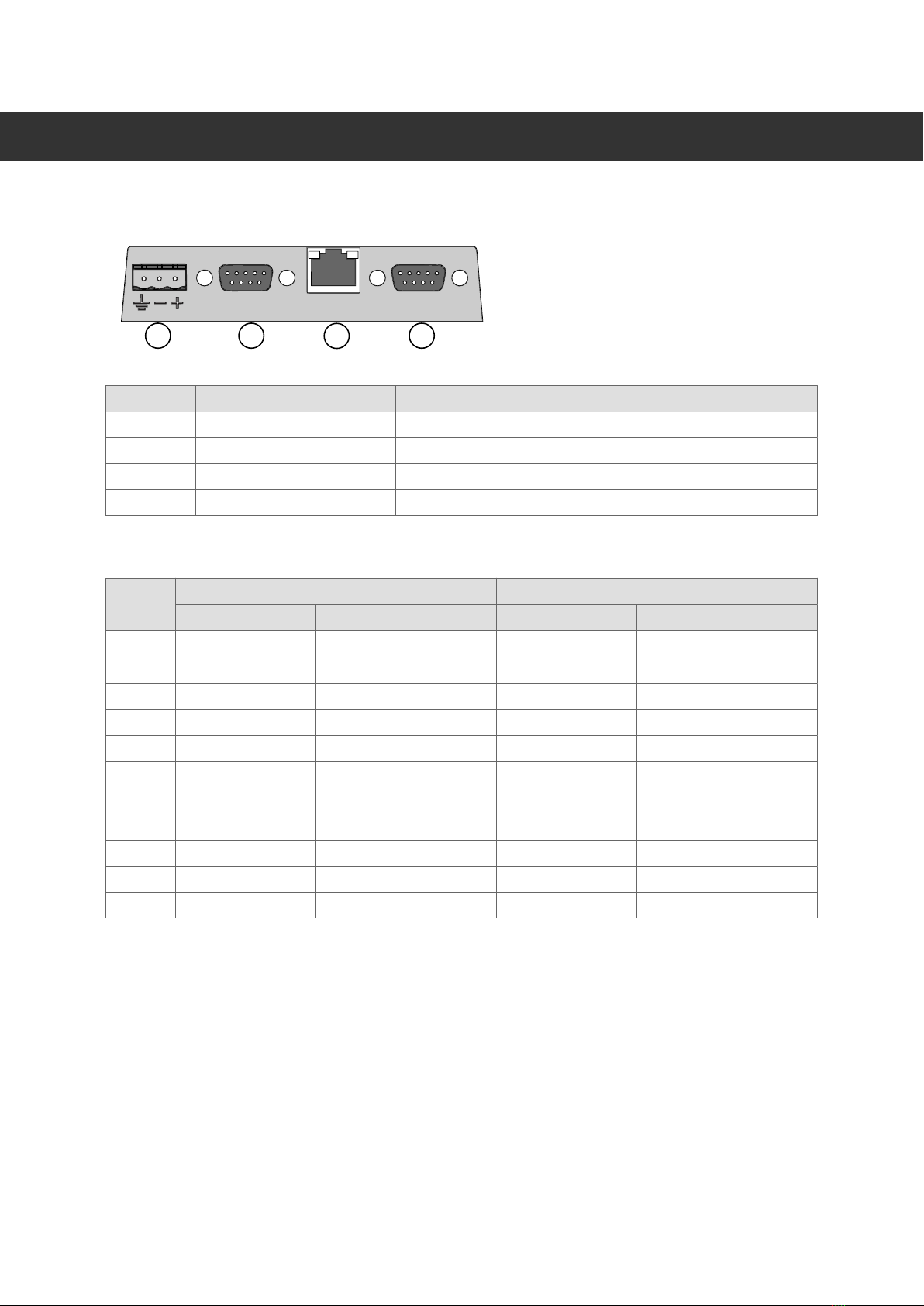
5. Device Drawings
5.1. Connectors
123 4
Pos Connector Description
1 Power supply +24 V DC (18–32 V DC)
2 COM-A Serial communication port
3 LAN 1×10/100 Base-T (shielded RJ45)
4 COM-B Serial communication port
5.1.1. Communication Ports
Pin Serial port, 9-pin female Serial port, 9-pin female
COM 1 COM 2 COM 3 COM 4
1 RS-422 TX+
RS-485 Tx+/Rx+
RS-485 Tx+/Rx+
2 RS-232 RxD RS-232 RxD
3 RS-232 TxD RS-232 TxD
4 RS-422 Rx+
5 GND GND GND GND
6 RS-422 TX-
RS-485 Tx-/Rx-
RS-485 Tx-/Rx-
7 RS-232 RTS
8 RS-232 CTS
9 RS-422 RX-
Device Drawings
Beijer Electronics, MAEN274 13 2023-09

6. Additional Installation Tips
When experiencing communication problems in noisy environments or when operating close to
temperature limits, the following recommendations are to be noticed.
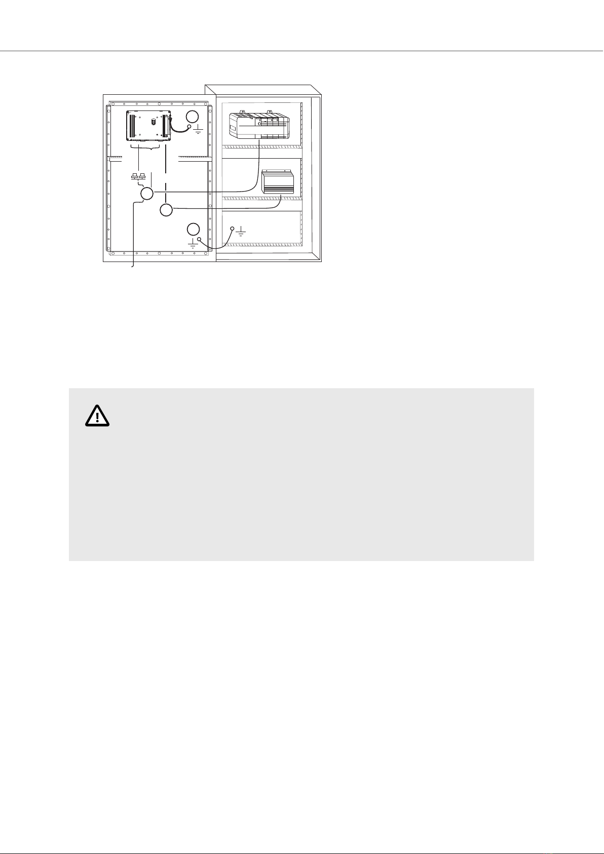
6.1. Grounding the Device
1
2
3
4
5
6
5350
Door
Box2 device
Ferrite core
Mounting plate in the cabinet
Power supply
24 V DC
The mounting clamps of the BoX2 device do not provide a secure grounding connection between the
device and the device cabinet, see 1 in drawing above. To ground the device:
1. Connect a wire, that is sized correctly according to local electrical codes, between the quick-
connect terminal connector on the device and the chassis of the device, see 2 in drawing above.
2. Connect a wire or grounding braid, that is sized correctly according to local electrical codes,
between the chassis of the device and the closest grounding point on the door, see 3 in drawing
above.
3. Connect a strong but short grounding braid between the door and the device cabinet, see 4 in
drawing above.
4. Twist the cables onto the 24 V DC feed, see 5 in drawing above.
• 2 turns around the ferrite core provide 4 times the suppression of 1 turn.
• 3 turns around the ferrite core provide 9 times the suppression of 1 turn.
NOTE
The grounding wires should be short and the conductor should have a large area.
A long, thin grounding wire has a very high impedance (resistance) at high
frequencies and does not guide disturbances to the ground.
Multi-wire conductors are better than single wire conductors with the same area.
A braided conductor wire with the same area is even better. The best is a short,
thick grounding braid.
Additional Installation Tips
Beijer Electronics, MAEN274 15 2023-09
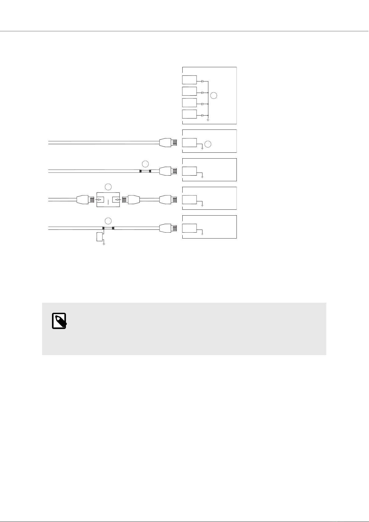
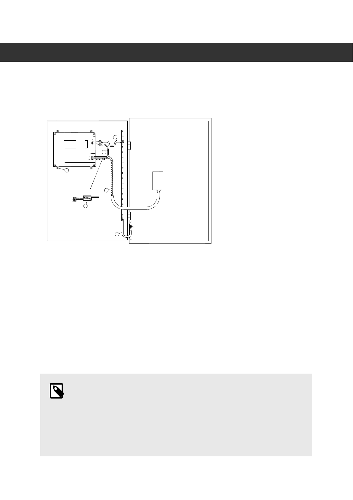
6.2. Ethernet Connection for the Device
1
2
3
4
5
RJ45
RJ45
RJ45
RJ45
RJ45
RJ45
RJ45
RJ45
Industrial Ethernet
BoX2 device
BoX2 device
BoX2 device
BoX2 device
Shielded
Short and
unshielded
0.1 õF
250 V
1-1
3-3
8-8
2-2
In some industrial units for Ethernet, the RJ45 contact’s shield is connected to the chassis via a
capacitor, see 1 in drawing above.
The Ethernet shield of the device is directly connected to the chassis, see 2 in drawing above.
Check whether the other Ethernet unit has its shield directly grounded or grounded via a capacitor.
NOTE
In many cases, connecting the shielded Ethernet cabling to the chassis at both ends
is inappropriate. Hum grounding loops can occur. Unshielded cabling may even result
in fewer communication errors.
A good solution may be to use a shielded Ethernet cable, but to connect the shield at one end only.
One option is to break the shield, see 3 in drawing above.
A more elegant method is to expand the shielded Ethernet cabling with a piece of unshielded
Ethernet cable, see 4 in drawing above.
The shield can be grounded via an external 0.1 μF / 250 V film capacitor, see 5 in drawing above.
This connects the HF transients to ground.
6.3. To Achieve Better EMC Protection
• Initially, use the original cabling from Beijer Electronics primarily.
• Place the 24 V DC and communications cabling in one cable trunk/cable duct and 230/380 V AC in
another. If the cables need to be crossed, cross them at 90° only. Avoid combining the cabling for
stronger 24 V DC outputs with the communication cabling.
Additional Installation Tips
2023-09 16 Beijer Electronics, MAEN274

• Use shielded cables for RS-232 communication.
• Use twisted pair and shielded cabling for RS-422 and RS-485.
• Use the cabling intended for the bus type; Ethernet, Profibus, CC-Link, CAN, Device Net etc.
• Install and connect according to applicable specifications for the relevant bus standard.
• Use shielded cabling for Ethernet, preferably with foil and a braided shield.
• D-sub covers should be shielded, and the shield should be connected to the cover 360° where the
cable enters.
• Connect the shield at both ends.
Shielded cable
Not same potential
Ground plane 1 Ground plane 2
Ground plate Ground plate in another building
0.1 µF/250 V
With longer distances, there is a risk that the ground potential may be different. In that case, the
shield should only be connected at one end. A good alternative is to connect the other end of the
shield to the ground via a 0.1 μF / 250 V film capacitor. Both ends are then connected to the ground
in terms of HF, but only connected to the ground at one end in terms of LF, thus avoiding the 50/60
Hz grounding loops.
Metal cabinet Metal cabinet
Te r minal or connector Te r minal or connector
EMC cable gland Plastic cable gland
Shielded cable
Short distance
Cable clamp
in steel
Shielded cable
1. Use an EMC cable gland or regular plastic cable gland, remove the outer jacket and connect the
shield to the installation plate with a 360° metal cable clamp.
2. Place the 24 V DC and communications cabling in one cable trunk/cable duct and 230/380 V AC
in another. If the cables need to be crossed, cross them at 90° only. Avoid combining the cabling
for stronger 24 V DC outputs with the communication cabling.
NOTE
Ferrite cores that are snapped onto the shielded cabling may remove minor
disturbances. Large ferrite pieces that are snapped onto unshielded cabling and
where the wires go 2-4 times around the cores are approximately 5-25 times more
efficient.
6.4. Ambient Temperature
The maximum ambient temperature for the BoX2 device is provided in the specifications. The
ambient temperature refers to the temperature in the device cabinet which cools the BoX2 device's
electronics.
Additional Installation Tips
Beijer Electronics, MAEN274 17 2023-09

BoX2
device
Power
Power
Power
30 °C outside
Top
50 °C inside
Bottom
40 °C inside
Middle
45 °C inside
Airflow
Axial fan
120 x 120 mm
In most cases, the ambient temperature for the BoX2 device is significantly higher than the device
cabinet’s ambient temperature.
If the cabinet is tall and there are several heat-generating devices, the temperature at the top of the
cabinet is considerably higher than the temperature increase that would be expected. All electronics
are sensitive to heat. The lifespan of an electrolytic capacitor is cut in half with an 8-10 °C increase
in temperature. A 15-20 °C temperature increase results in a quarter of the lifespan etc.
Rittal has a good program for estimating the anticipated average temperature in the cabinet as well
as a large program for controlling the temperature in the device cabinet.
An enamel-coated steel cabinet has a radiant heat value of 5.5 W/m2 per °C.
Installing a fan inside the cabinet evens out the temperature, while moving air provides considerably
better cooling than still air.
Install the fan so that it sits in a cooler area and blows cold air against the BoX2 device. If the fan
is mounted at the top and sucks warm air upwards, the ambient temperature of the fan becomes
higher, resulting in a shorter lifespan.
An approximate value of the net power consumption for the device can be calculated by multiplying
the supply voltage with the current drawn by the device. This is assuming that all supplied power is
transformed to heat.
NOTE
Please ensure that the temperature will not exceed the maximum ambient operating
temperature in the enclosure. This can be influenced by other heat generating
devices.
Additional Installation Tips
2023-09 18 Beijer Electronics, MAEN274

6.5. Safety
4
1
2
4
3
4
Power supply
230 V AC to 24 V DC
Power supply
230 V AC to 24 V DC
Power supply
230 V AC to 24 V DC
BoX2 device
BoX2 device
BoX2 device
Distance?
Small controller with expansion unit
+24 V
+24 V
+24 V
0 V
0 V
0 V
230 V AC
COM1
COM100
Ch0
Ch1
Ch100
Ch101
5355
If a power supply that meets safety standards is used and only powers the BoX2 device, there is no
problem. See 1 in drawing above.
However, if a 24 V unit that also powers other units is used, there is reason to be cautious, see 2 in
drawing above. The device does not have insulation that meets safety requirements in the event of
a potential short circuit between 230 V AC and 24 V DC. It is assumed that the 24 V power supply is
secure, for example, SELV according to EN 60950 (protection against electric shock) and UL 950.
NOTE
Here is an example that explains why a secure 24 V DC power supply can be ruined
by mixing 24 V relay contacts with 230 V AC relay contacts in a smaller controller.
Check that the clearances and creepage distances between 24 V DC and 230 V AC
fulfill EN 60950 or UL 950. If not, input a separate 24 V unit into the device.
If there is a substantial distance between the relay contacts for 24 V DC and 230 V AC, it is OK to use
the same 24 V devices for all feeds. See 3 in drawing above.
Connect 0 V on the 24 V power supply to the ground, see 4 in drawing above. This offers three
advantages:
• Safety is increased. The 24 V power supply is not live in the event of a faulty connection or short
circuit between 0 V (24 V) and 230 V phase.
• Transients on the 24 V feed are connected to the ground.
• No risk that the 24 V feed is at a high level in relationship to the ground. This is not unusual since
there is high static electricity.
Additional Installation Tips
Beijer Electronics, MAEN274 19 2023-09

6.6. Galvanic Isolation
* *
*
***
**
*
Operator panel Modular controller Printer
PCPC
Different ground potential
* = Internal 0 V (GND) connection
Power CPU COM COM2
RS422 RS232 USB
When a PC is connected to the HMI panel, the internal 0 V (GND) of the panel is connected to the
protective ground via the PC.
A number of USB devices can have the shield connected together with the protective ground. Here,
the 0 V (GND) of the HMI panel is connected to the protective ground when, for example, a USB
memory stick, keyboard, or similar device is plugged in.
If a number of units are connected that have a 0 V and a ground connection, and these are connected
to various grounding points, there is a substantial risk of problems. Grounding currents go through
communication cables, the rear plate of the controller, internally in the HMI panel, and can cause
errors.
Use external units to improve communication and achieve galvanic isolation. Westermo has good
industry-standard insulators that are also insulated from the 24 V DC feed.
NOTE
It is very important to make sure that the 24 V feed in the external insulation unit
is not connected to one of the communication outlets. If it does not have 100%
insulation against the 24 V feed, disturbances and grounding currents from the 0 V on
the 24 V side disrupt the communication.
Using this type of unit solves one problem but creates a larger problem! A
substandard installation may work now, but problems may arise when other devices
are connected.
6.7. Cable and Bus Termination RS-485
• If maximum transfer distance and maximum transfer speed is needed, shielded and twisted pair
cable should be used. The mutual capacitance may not exceed 52.5 pF/m, and the cable area
should be at least 0.25 mm2 (AWG 24).
• 0 V, the reference voltage for communication should be included in the cabling. With two-way
communication use two pairs; one pair for communication and one pair for 0 V.
• The shield must be grounded at one end. The other end is usually grounded, but with longer
distances or when there is a difference in the ground potential, the shield should be connected to
the ground via 0.1 μF / 250 V film capacitor to prevent ground current in the braided shield. Some
manufacturers recommend that the shield be grounded at each node. Various manufacturers have
different systems for bus termination.
Depending on the recipients’ design, the bus wires may be on the same level or require pull-up
or pull-down to ensure that no faulty signals are detected when the bus is in resting mode (all
transmitters are disconnected).
Additional Installation Tips
2023-09 20 Beijer Electronics, MAEN274
Other manuals for BoX2 extreme
2
Table of contents
Other Beijer Electronics Media Converter manuals

Beijer Electronics
Beijer Electronics BoX2 pro User manual

Beijer Electronics
Beijer Electronics JetCon 1701GP-U User manual

Beijer Electronics
Beijer Electronics BoX2 base v2 Instruction sheet

Beijer Electronics
Beijer Electronics 100-0973 User manual

Beijer Electronics
Beijer Electronics BoX2 extreme User manual


