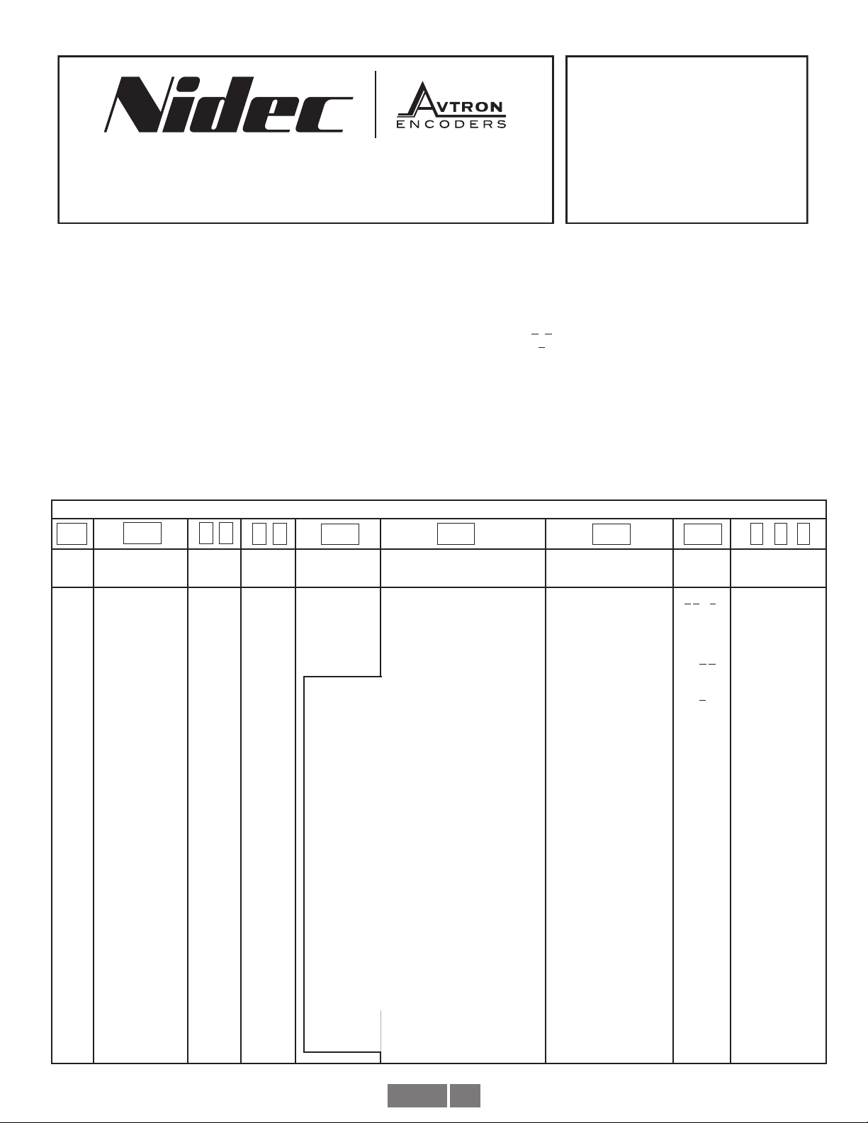
Nidec Avtron AV45 Series User manual

AV45 1
8901 E. PLEASANT VALLEY ROAD
•
INDEPENDENCE, OHIO 44131-5508
TELEPHONE: (1) 216-642-1230
•
FAX: (1) 216-642-6037
E-MAIL:[email protected]
•
WEB: www.avtronencoders.com
Nidec-Avtron Makes the Most Reliable Encoders in the World
Encoder
Instructions
AV45
SOLID SHAFT
B10 FLANGE OR FOOT MOUNT
AV45 PART NUMBERS AND AVAILABLE OPTIONS
Model Shaft Size
Left
Output
PPR
Right
Output
PPR
Line Driver Connector Options Foot Mount Bracket Channels Modifications
AV45 H- 11mm, standard
N- 10mm
P- 12mm
Q- 0.500”
S- 16mm
T- 18mm
XX-None
BC-50
AF-60
AK-80
AG-100
AH-120
AA-128
AM-200
AL-240
AN-256
AP-300
AE-360
AC-400
AB-480
AQ-500
AR-512
AS-600
AU-720
AV-900
AJ-960
AW-1000
AY-1024
AZ-1200
CX-1500
A3-2000
A4-2048
A5-2500
AT-3072
A7-3600
AD-4096
A8-4800
A9-5000
A0-Special
XX-None
BC-50
AF-60
AK-80
AG-100
AH-120
AA-128
AM-200
AL-240
AN-256
AP-300
AE-360
AC-400
AB-480
AQ-500
AR-512
AS-600
AU-720
AV-900
AJ-960
AW-1000
AY-1024
AZ-1200
CX-1500
A3-2000
A4-2048
A5-2500
AT-3072
A7-3600
AD-4096
A8-4800
A9-5000
A0-Special
Note Dual
Output NA
with Foot
Mount Bracket
6- 5-24V in/out
(7272)
8- 5-24V in/out
(HX)
9- 5-24V in,
5V out (7272)
10 Pin MS Connector-
Small Encoder Pinout
A- Avtron/BEI Pinout, w/o plug
B- Dynapar HS35 Pinout, w/o plug
C- Avtron/BEI Pinout, mating plug
D-Dynapar HS35 Pinout, mating plug
Y-12” cable w/plug
X- None
(for B10 flange mount)
1- Toshiba TS2113N bolt
pattern (recommend “T”
18mm shaft)
(B35529 bracket)
2- POGxx, OGxx Hubner
(Baumer) bolt pattern
(B35555 bracket)
3- FG4 Johannes Hubner
bolt pattern
(B35338 bracket)
4- Foot mount for Toshiba
type MSP
5- 2.50” pilot flange
A- All
A,B,A,B,Z,Z
(req’d for 8,
10 pin con-
nectors)
B- A,B,A,B
(no marker)
D- A,A
E- A,B,Z
(single
ended)
F- A,B
(single
ended, no
marker)
000- None
004- Super
Magnetic
Shielding
6xx- Add over
speed switch
xx=speed
code
9xx- Specify cable
length xx=feet
max 33ft
(use w/ Option
“W”)
001- Isolated
bearings
DESCRIPTION
The Avtron Model AV45 is a heavy duty incremental encoder (also
known as tachometer or rotary pulse generator). Its output is directly
proportional to shaft position (pulse count) or speed (pulse rate). The
AV45 operates down to zero speed and can be used for both control
and instrumentation applications.
CAUTION
Do not utilize AV45 in hazardous locations which
require ATEX, UL, CUL, CSA, or other explosion protection
certification. AV45 is not certified for hazardous
locations. Use XR models for hazardous applications.
The AV45 is designed for mounting on European B10 style flanges
(85mm flange, 100mm bolt circle), or on a foot mount bracket for
coupling. The AV45 is not recommended for pulley or chain drive
applications.
The AV45 utilizes magnetoresistive sensors. This proven technology
is ideal for rugged environments since it is immune to many
contaminants that cause optical encoders to fail. All of the AV45
electronics are potted, providing full protection against liquids. The
outputs are protected against short circuits and wiring errors.
Each AV45 has a two-phase output (A, B) 90° out of phase, with
complements (A, B), (A Quad B Output). A marker pulse with
complement (Z, Z) is also present.
The AV45 has a diagnostic package that includes Adaptive Electronics
and a Fault-Check output and red/green LED for local indication. With
this package, the AV45 can maintain itself, and provide an alarm if
there is a problem before the problem causes unscheduled downtime.
10 Pin MS Connector- Large Encoder Pinout
4-Avtron/Northstar Pinout, mating plug
6 Pin MS Connector- Small Encoder Pinout
E- Avtron/BEI Pinout, w/o plug
F- Dynapar HS35 Pinout, w/o plug
7 Pin MS Connector- Small Encoder Pinout
J- Avtron/BEI Pinout, w/o plug
K- Dynapar HS35 Pinout, w/o plug
M-4 foot cable w/o plug, channel B
Small EPIC Connector
P- Avtron pinout, w/mate
G- Northstar pinout w/mate
Q- Avtron pinout on remote base, 18” cable w/mate
Z- Avtron pinout on 18” cable w/mate
Terminal Box w/terminal strip
H- USA, 1/2” conduit
L- Europe w/cord grip
8 Pin M12 Connector
T- Global pinout, w/o plug
U- USA Pinout, w/o plug
12 Pin M23 Connector
2- Leine and Linde pinout, w/o plug
3- Hubner Pinout w/o plug
W- Cable 3’ (or special length)
R- Mini Twist Lock (Mini MS) w/ mating plug
V-
Mini Twist Lock (Mini MS) w/ mating plug (Reverse Phasing)
S- Mini Twist Lock (Mini MS) on 3’ cable w/mating plug
N-
Mini Twist Lock (Mini MS) w/o plug (Reverse Phasing)

AV45 2
ADAPTIVE ELECTRONICS
A perfect duty cycle consists of a waveform whose “high” and
“low” conditions are of the same duration (50%/50%). It is possible
over time for the duty cycle and edge separation to change due
to component drift, temperature changes, or mechanical wear.
The Adaptive Electronics extend the life of the AV45 by constantly
monitoring and correcting duty cycle and edge separation over time.
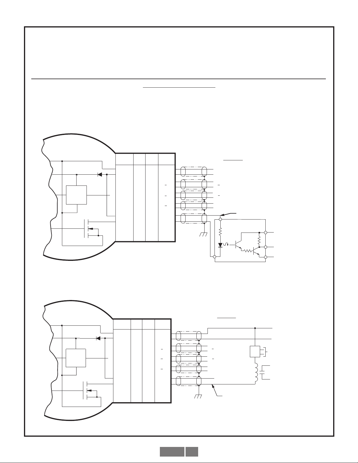
FAULT-CHECK
If the Adaptive Electronics reach their adjustment limit, the LED will
turn red and Fault-Check alarm will notify the drive and operator of
an impending failure. This output can occur before a failure, allowing
steps to be taken to replace the unit before it causes unscheduled
downtime. Fault-Check annunciation is available as an “alarm” output
through the connector.
SAFETY
The AV45 is not considered as a safety device and is not suitable for
connection into a safety system. The mechanical overspeed switch
(option 6xx) is suitable for connection into safety systems.
CAUTION
Do not disassemble mechanical overspeed option. Doing
so may modify the overspeed set point or cause the
switch to malfunction. If the factory seals are not intact
on the overspeed switch, do not use it--return to the
factory for service and calibration.
WARNING
Installation should be performed only by qualified
personnel. Safety precautions must be taken to ensure
machinery cannot rotate and all sources of power are
removed during installation.
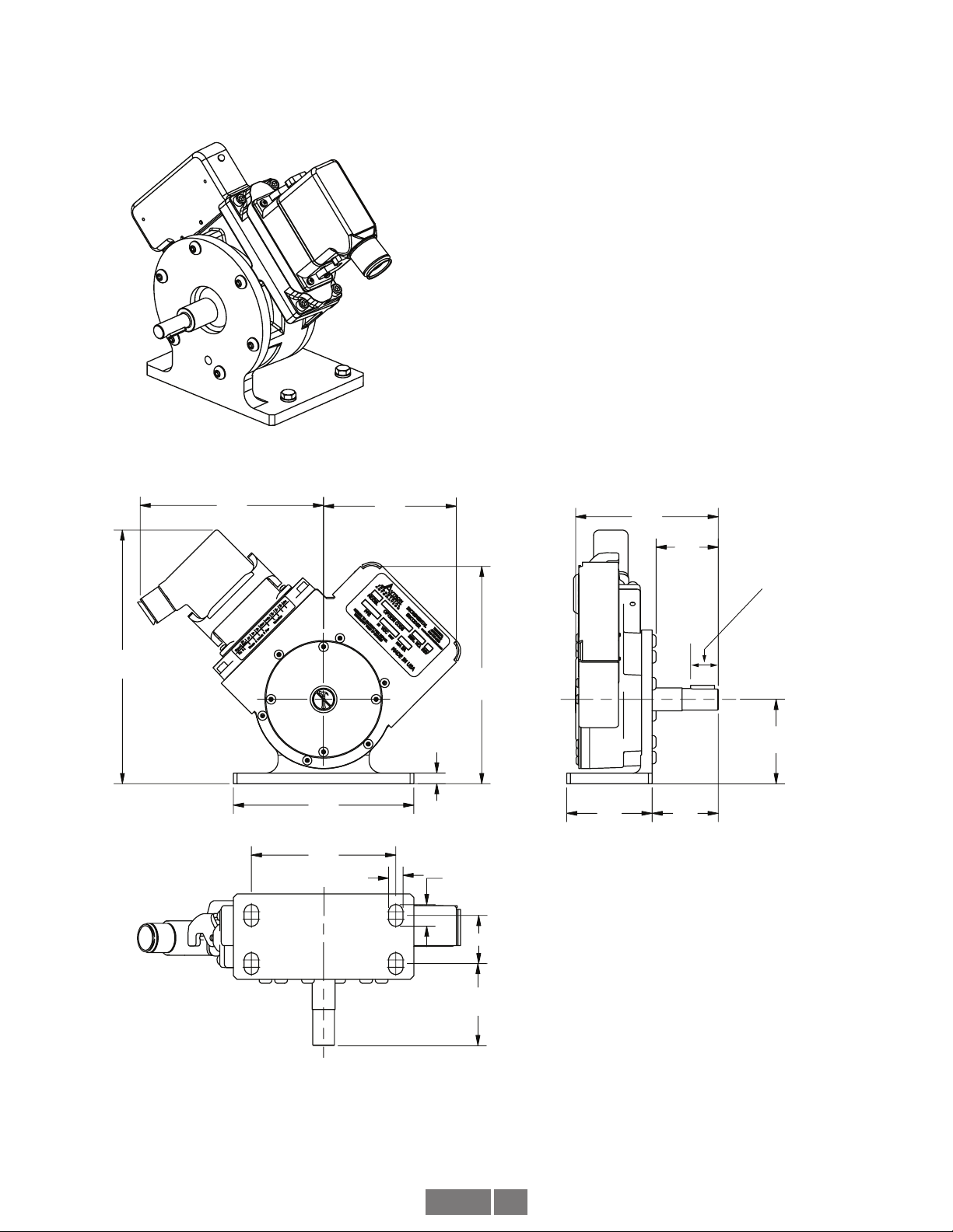
INSTALLATION
Refer to the back page of these instructions for outline and mounting
dimensions.
Supplied:
AV45 Encoder
Optional:
Foot Mount Kit
Thread Locker (blue)
Not Supplied:
Dial Indicator Gauge
Caliper Gauge
The encoder must be driven by a positive drive rather than a friction
drive. The following means of coupling are acceptable when properly
installed: Direct Coupling.
With a direct drive, use a flexible disc coupling and align the shafts as
accurately as possible. For motors with a pre-aligned flange, it is also
acceptable to use a “spider” or “jaw” coupling type. If a rubber slinger
disc is used, position it on the shaft so it will rotate freely.
CAUTION
Do not force or drive the coupling onto the shaft, or
damage to the bearings may result. The coupling should
slide easily on the shaft. Remove nicks and burrs if
necessary. Consider driving shaft endplay & axial
movement when positioning coupling.
For more details on alignment specifications, measurement
techniques, and special considerations in specifying and installing
drive components, refer to separate installation instructions in the
Avtron PULSE GENERATOR HANDBOOK.
B10 FACE MOUNTING INSTRUCTIONS
1. Apply anti-seize compound [copper], included, to inner
circumference of coupling (both motor and encoder side).
2. Loosen set screws in coupling and apply thread locker to set
screws.
3. Place coupling on motor shaft, inserting to depth per
manufacturer’s instructions.
4. Attach coupling to motor shaft using set screws per
manufacturer’s instructions.
5. Bolt mounting flange (flowerpot) to motor C-Face, using thread
locker with fasteners, included.
6. Slide encoder shaft into other side of coupling. DO NOT FORCE.
Ensure keyway aligns with coupling set screw location.
7. Ensure C-Face on mounting flange matches and aligns with
encoder C-Face precisely.
8. Apply thread locker to hex cap screws.
9. Align bolt holes of encoder and flange, thread in (4) hex cap
screws, using lock washers.
10. Tighten set screws on encoder side of coupling.
FOOT MOUNTING INSTRUCTIONS
Equipment needed for installation
Supplied:
Foot Bracket
(6) M6 Button Hd. Cap Screw
Not Supplied:
M4 Hex Wrench
Dial Indicator
The B10 flange / face is the preferred mounting method for the AV45.
In certain cases, however, it may be necessary to foot-mount this
unit. The optional foot mounting bracket kits, Option 1, 2, or 3, will be
required for standard installations or replacement of foot mounted
Toshiba TS2113N, Hubner HOG & OG, and FG4 units. Read all of the
following instructions and the Avtron PULSE GENERATOR HANDBOOK
prior to beginning any work.
The AV45 performance and life will be directly affected by the
installation. Following this sequence of steps is recommended.
1. Clean and inspect motor/driver shaft. Do not use force to
assemble coupling onto motor/driver shaft. The foot mounting
bracket must be secured to a flat, rigid, vibration free steel or
aluminum base which can be machined to accept the mounting
hardware.
2. Temporarily mount the AV45 to the foot bracket, install the
coupling to the AV45 and driver, and verify that the location is
suitable for installation.
3. If the AV45 encoder, bracket and coupling are suited to the area,
check motor/encoder shaft alignment with a straight edge from
multiple positions around the shaft circumference to verify that it
meets specifications.
4. While maintaining alignment, precisely mark the position of the
foot bracket on its mounting base.
5. Remove the AV45. Transfer punch or layout the mounting hole
pattern as indicated on outline drawing.
6. Machine through holes or tap holes in center of base slots to give
some degree of freedom in final alignment.
7. Reinstall the AV45 with the flexible coupling loosely in place, and
tighten down all mounting hardware. Check motor/encoder shaft
alignment with a straight edge from multiple positions around
the shaft circumference to verify that it meets specifications. Use
thread locker supplied on cap screws which mount AV45 to foot
bracket.
8. Ensure any flat or keyway on the motor and encoder shaft
are aligned with the set screw holes of the flexible coupling.
Apply thread locker to coupling set screws and tighten per
manufacturer’s recommendations.
9. Recheck alignment and tighten all hardware after first several
hours of operation.

AV45 3
FAULT-CHECK
After power-up and the rotor position is checked by the sensor, the
Fault-Check LED will turn green
If the adaptive electronics reach their adjustment limit for any reason,
the Fault-Check alarm and LED will notify the drive and operator of
an impending failure. The LED will turn red if the Adaptive Electronics
reach their adjustment limit. This output occurs before an actual
failure, allowing steps to be taken to replace the unit before it causes
unscheduled downtime. Fault-Check annunciation is available as an
“alarm” output through the connector and as an integral LED.
TROUBLESHOOTING
If the drive indicates a loss of encoder/tach fault and the AV45
fault-check LED is not illuminated, check the encoder power supply.
If power is present, check polarity; one indicator of reversed power
supply is that all outputs will be high at the same time. If the drive
indicates encoder fault, but the LED shows GREEN, then check the
wiring between the drive and the encoder. If the wiring appears
correct and in good shape, test the wiring by replacing the AV45. If the
new unit shows GREEN, and the drive still shows encoder loss/tach
fault, then the wiring is faulty and should be repaired or replaced.
If the alarm output and/or LED indicate a fault (RED) on a properly
mounted AV45 and the rotor is properly located, replace the AV45.
An oscilloscope can also be used to verify proper output of the
AV45 encoder at the encoder connector itself and at the drive/
controller cabinet. If the outputs show large variations in the signals
at steady speed (jitter or “accordion effect”, see figure 5), replace any
magnetized material nearby with non-magnetic material (aluminum,
stainless) (shafts, etc). If variations persist, consider replacing with
super-shielded models, option -004.
VARIATION > ± 15%
PHASE A
PHASE B
MODIFICATION
The AV45 can be modified in the field to easily adapt to new
applications.
TO CHANGE ELECTRICAL CONNECTOR STYLE:
1. Remove electrical power and disconnect the mating plug.
2. Unscrew the (4) M5 screws (4mm hex).
3. Pull the connector header away from the encoder gently.
4. Disconnect the ribbon connector to the encoder body.
5. Connect the ribbon connector to the new connector header
6. Attach the new connector header to the encoder using the (4)
M5 screws. Tighten to 30 in-lbs [3.4n-m]. Be sure the ribbon
connector fits in the open pocket under the header and is not
crushed or pinched by the connector header.
WIRING
CAUTION
Be sure to remove power before wiring the encoder.
Be sure to ground the cable shield: at the drive end. See
note below for Danaher/Northstar wiring.
Refer to the wiring diagrams for specific information on each option.
The AV45 can be wired for single phase or two phase, either with
or without complements, with or without markers. For bidirectional
operation, Phase A channel leads phase B channel for clockwise shaft
rotation as viewed from the anti-drive or accessory end of the motor
(AV45 mounting end).
CAUTION
Be sure to observe maximum current limits for
mechanical overspeed switch option. Exceeding these
limits can cause arcing and cause switch failure; this
may result in property damage, injury or even death.
NOTE
Wiring option “G” provides a pinout compatible with
NorthstarTM encoders, with a cable shield connection
on pin 10. Note that this option does not ground the
shield; Avtron still recommends grounding the shield at
the drive end of the cable for all wiring options.
CORRECTIVE ACTION FOR PHASE REVERSAL
1. Remove Power.
2. Exchange wires on cable, either at encoder cable end, or at
speed controller end (but not both).
a) Single Ended 2 Phase Wiring (see wiring diagram) Exchange
A and B at the use end of the wires.
b) Differential 2 Phase Wiring (see wiring diagram) Exchange
either A with Ain the phase A pair OR B with Bin the phase B
pair but NOT both.
3. Apply Power.
4. Verify encoder feedback is correct, using hand rotation of shaft,
or jog mode of the speed controller.
Interconnecting cables specified in the wire selection chart are based
on typical applications. Physical properties of cable such as abrasion,
temperature, tensile strength, solvents, etc., are dictated by the
specific application. General electrical requirements are: stranded
copper, 22 through 16 AWG (Industrial EPIC connector type options
can use 14 AWG), each wire pair individually shielded with braid or foil
with drain wire, .05 uf of maximum total mutual or direct capacitance,
outer sheath insulator. See specifications for maximum cable length.
Stranded 22 AWG wire should not be used for cable runs greater then
61 meters. If 22 AWG is used with EPIC type connector options the
wire ends should be tinned.

AV45 4
ELECTRICAL SPECIFICATIONS
A. Operating Power (Vin)
1. Volts............................ 5-24 VDC in
2. Current ....................... 100mA, nominal, plus cable load
B. Output Format
1. 2O/ & Comp ................ A,A
–, B,B
–(differential line driver)
2. Marker: ....................... 1/Rev Z, Z
–
C. Signal Type..................... Incremental, Square Wave, 50 +/-10%
................................... Duty Cycle.
D. Direction Sensing ........... O/ A leads O/ B for CW rotation as viewed
................................... from the back of the tach looking at the
................................... non-drive end of the motor.
E. Transition Sep. ............... 15% minimum
F. Frequency Range........... See below
G. PPR ................................ 3-2500***
H. Line Driver Specs: .......... See table
I. Connectors: .................... See connector options on page 1
MECHANICAL
A. Shaft Inertia .................... 1.24 lb-in-sec2
B. Acceleration.................... 5000 RPM/Sec. Max.
C. Speed: ............................ 5000 RPM Max (also see overspeed)****
D. Weight: ........................... 10-12 lbs [4.5-5.5kg]
E. Vibration ......................... 20 Gs, 5-2000 Hz (any orientation)
F. Shock ............................. 100 Gs, any orientation
G. Shaft Load:.....................
****(Speed) Maximum RPM may be limited for PPR > 2,500 consult
factory with your application
ENVIRONMENTAL
Solid cast aluminum stator and rotor
Fully potted electronics, protected against oil and water spray
Operating Temperature:.......-40°C to +100°C.
MECHANICAL OVERSPEED SWITCH OPTION
A. Shaft Inertia .................... +0.0018 lb-in-sec2
B. Acceleration.................... 3600 RPM/Sec. Max.
C. Speed: ............................ 1.25 x Overspeed set point Max.
Minimum trip speed: 700 RPM
Maximum trip: 3600 RPM
Accuracy +/- 4% of trip point
Hysteresis: 40% of trip point
D. Weight:............................ +2.55 lbs [+1.16kg]
E. Vibration: ........................ 20 Gs, 5-2000 Hz (radial only)
F. Shock: ............................ 100Gs, any orientation
G. Electrical Contact (NO/NC Contact)
1. ................................... 6A/230VAC
2. .................................... 3A/380VAC
3. .....................................1A/125VDC
H. Operating Temperature:......-40°C to +100°C.
LINE DRIVER OPTIONS
Electrical Specifications 6 8 9 Units
Input Voltage 5-24 5-24 5-24 VDC
Nom Output Voltage 5-24 5-24 5 VDC
Line Driver 7272 HX 7272
Output Resistance Typ
13 75 13 ohms
Maximum Peak Current 1500 800 1500 mA
Maximum Average
Current 120 200 120 mA
Voh Typ VIN-1 VIN-1 VIN-1 VDC
Vol Typ 0.5 0.4 0.5 VDC
Cable Drive Capacity
1000’ @ 5V
500’ @ 12V
200’ @ 24V
1000’ 1000’ feet
Protection
Reverse
Voltage yes yes yes
Short
Circuit yes yes yes
Transient yes yes yes
Mis-Wiring yes yes yes
Alarm
+V(out) Output voltage equal to input voltage.
Alarm* Open collector, normally off, goes low on alarm,
sink 100mA max, 50VDC max
Marker One per revolution. Pulse width
1/4 AB Period. Gated with A&B High
Frequency Range: @5V, @1m cable, 250 kHz Max
@24V, @300m cable, #8 output, 45 kHz Max
Max Cable Lenght: 300m
*** (PPR) Standard PPR is 5000. Consult factory with your application
for PPRs up to 25,000
LED
Green = Power on
Red = Alarm
Orange = Line Driver Shutdown (Due
to thermal overload or undervoltage)
A
B
Z
Timing Diagram (A leads B for CW rotation)

AV45 5
Example 2. Alarm Output Using Separate 24 VDC Power Supply and Relay.
Applies to Model AV45 Encoders connector styles “H”, “L”, “P”, “W”
ALARM OUTPUT CONNECTION
Avtron AV45 encoders provide an alarm signal if maintenance is required under specific circumstances. Following are application
examples provided to help install the alarm output.
Example 1. Alarm output using +V(OUT). +V(OUT) is equal to +V, the encoder power supply.
NOTE: Alarm output is “low true”; i.e., goes to OV when active.
AV45
Remote Alarm
BLACK
RED
GREEN
YELLOW
BLUE
GRAY
ORANGE
WHITE
BROWN
VIOLET
OUTPUT OPTIONS
A
B
D
G
E
H
C
I
F
J
9
4
5
10
2
8
3
7
6
1
+V(OUT)
Z
Z
A
B
B
A
+V
COM
Vcc
OUT
COM
300 OHM
MIN.
GND
FUNCTION
ENCODER
ØB
ØA
ØA
ØB
4-16 VDC SOLID STAT E RELAY
LINE
DRIVER
{
FUNCTIONAL DIAGRAM
50 mA MAXIMUM
“W”“4”“P”,“Q”,
“Z”“H”, “L”
ALM
MARKER
MARKER COMPLEMENT
COMMON
+V (Encoder Power)
{
BLACK
RED
GREEN
YELLOW
BLUE
GRAY
ORANGE
WHITE
BROWN
VIOLET
“H”,“L”
OUTPUT OPTIONS
A
B
D
G
E
H
C
I
F
J
9
4
5
10
2
8
3
7
6
1
ALM
+V(OUT)
Z
Z
A
B
B
A
+V
COM
MARKER
MARKER COMPLEMENT
GND
FUNCTION
+V (Encoder Power)
COMMON
24
VDC
RELAY
+
-
POWER
SUPPLY 115 VAC
SINK 100 mA MAXIMUM,
WITHSTAND 50 VMAXIMUM
REFERENCED TO COMMON
ENCODER
FUNCTIONAL DIAGRAM
ØB
ØA
ØA
ØB
LINE
DRIVER
“W” “4” “P”,“Q”,
“Z”

AV45 6
WIRING DIAGRAMS
Avtron standard warranty applies. Copies available upon request.
Specifications subject to change without notice.
OPTION
“W”
(CABLE)
AABB B
OPTIONS
“A”, “B”, “C”, “D”
(10 PIN MS)
PINOUT
OPTIONS
“J”, “K”
(7 PIN MS)
BLACK
RED
GREEN
YELLOW
BLUE
GRAY
ORANGE
WHITE
BROWN
VIOLET
BROWN
VIOLET
BROWN
VIOLET
DIFFERENTIAL TWO PHASE WIRING APPLICATIONS
F
D
A
H
B
I
C
J
F
D
A
C
B
E
NC
NC
NC
NC
NC
NC
F
D
A
C
B
E
NC
NC
NC
NC
OPTIONS
“E”, “F”
(6 PIN MS) (8 PIN M12) (8 PIN M12)
(8 PIN M12) (8 PIN M12)
A
B
E
C
D
F
NC
NC
NC
NC NC NC
NC
NC
ØA, ØA
–
ØB, ØB
–
ØZ, ØZ
–
ØA, ØA
–
ØB, ØB
–
ØZ, ØZ
–
ØA, ØA
–
ØB, ØB
–ØA, ØA
–
ØB, ØB
–ØA, ØA
–
ØB, ØB
–
CHANNELS CONNECTOR
<<CONNECTED ON 18" CABLE
* NC ON CHANNEL OPTION “B”
<< CONNECTED ON 18" CABLE
1
2
3
4
5
6
7
8
7
2
1
3
4
5
6
8
OPTIONS
“T”
OPTIONS
“U”
OPTIONS<<
“U”
A
ØA, ØA
–
ØB, ØB
–
ØZ, ØZ
–
A
ØA, ØA
–
ØB, ØB
–
ØZ, ØZ
–
OPTION “W”
(CABLE)
A
OPTIONS
“A”, “B”, “C”, “D”
(10 PIN MS)
PINOUT
OPTIONS<<
“J”, “K”, “M”, “N”
(7 PIN MS)
RED
BLUE
GREEN
BLACK
ORANGE *
SINGLE ENDED TWO PHASE WIRING APPLICATIONS, WITH OR WITHOUT MARKER | NOT RECOMENDED FOR OUTPUT OPTION “8”
D
B
A
F
C*
D
B
A
F
C*
OPTIONS<<
“E”, “F”, “G”, “H”
(6 PIN MS)
B
D
E
A
C*
E, F
ØA, ØB, ØZ
E, F
ØA, ØB, ØZ
E, F
ØA, ØB, ØZ
CHANNELS CONNECTORS
* NC ON CHANNEL OPTION “F”
^ COMPLEMENTS INCLUDED BUT NOT USED
22
54
1
3
1
7
7
6
A
ØA, ØA
–^
ØB, ØB
–^
ØZ, ØZ
– ^
ØA, ØA
–
ØB, ØB
–
ØZ, ØZ
–
ØA, ØA
–
ØB, ØB
–
ØZ, ØZ
–
A
OPTION “W”
(CABLE)
OPTIONS
“A”, “B”, “C”, “D”
(10 PIN MS)
PINOUT
OPTIONS<<
“J”, “K”, “M”, “N”
(7 PIN MS)
BLACK
RED
GREEN
SINGLE ENDED SINGLE PHASE WIRING APPLICATIONS | NOT RECOMENDED FOR OUTPUT OPTION “8”
F
D
A
F
D
A
OPTIONS<<
“E”, “F”, “G”, “H”
(6 PIN MS)
A
B
E
ØA
(ØA
–INCLUDED
BUT NOT USED)
ØA
(ØA
–INCLUDED
BUT NOT USED)
ØA
(ØA
–INCLUDED
BUT NOT USED)
DDD
CHANNELS CONNECTORS
1
2
3
7
2
1
OPTIONS<<
“T”
OPTIONS<<
“U”
A
ØA
–, ØB,
ØB
–, ØZ, ØZ
–ØA
–, ØB,
ØB
–, ØZ, ØZ
–
A
(ØA
–, ØB,
ØB
–, ØZ, ØZ
–
INCLUDED BUT
NOT USED)
A
OPTIONS<<
“T”
AA AA
5NC
NC10
F
D
A
H
B
J
C
K
1
6
2
7
3
8
4
9
NC
NC
1
6
2
7
3
8
4
9
F
J
A
B
D
G
E
H
C
I
ØA, ØA
–
ØB, ØB
–
ØZ, ØZ
–
ØA, ØA
–
ØB, ØB
–
ØZ, ØZ
–
OPTIONS
“R”, “S<<”
(10 PIN
TWIST-LOCK)
OPTIONS
“P”, “Q ”,“Z<<
<< ”
(10 PIN
INDUSTRIAL)
D
B
A
F
6
3
2
1
4C
6
3
2
1
4
B
E
D
A
C
AA
ØA, ØA
–
ØB, ØB
–
ØZ, ØZ
–
ØA, ØA
–
ØB, ØB
–
ØZ, ØZ
–
OPTIONS
“P”, “V”,“Z<<”
OPTIONS
“R”, “S<<”
(10 PIN
INDUSTRIAL)
(10 PIN
TWIST-LOCK)
1
6
2A
F
D
1
6
2D
A
B
AA
ØA, ØA
–
ØB, ØB
–
ØZ, ØZ
–
ØA, ØA
–
ØB, ØB
–
ØZ, ØZ
–
OPTIONS
“P”, “V”,“Z<<”
OPTIONS
“R”, “S<<”
(10 PIN
INDUSTRIAL)
(10 PIN
TWIST-LOCK)
ØA, ØA
–
ØB, ØB
–
ØZ, ØZ
–
A
ØA, ØA
–
ØB, ØB
–
ØZ, ØZ
–
ØA, ØA
–
ØB, ØB
–
ØZ, ØZ
–
A
ØA, ØA
–
ØB, ØB
–
ØZ, ØZ
–
A
ØA, ØA
–
ØB, ØB
–
ØZ, ØZ
–
A
ØA, ØA
–
ØB, ØB
–
ØZ, ØZ
–
A
ØA, ØA
–
ØB, ØB
–
ØZ, ØZ
–
A
ØA, ØA
–
ØB, ØB
–
ØZ, ØZ
–
OPTIONS
(10 PIN MS)
A
5
10
1
6
2
7
3
8
4
9
ØA, ØA
–
ØB, ØB
–
ØZ, ØZ
–
OPTIONS
CONDUIT BOX
OPTIONS
CONDUIT BOX
OPTIONS
“G” “4”
OPTIONS
(12 PIN M23)
“2”
OPTIONS
(12 PIN M23)
“2”
OPTIONS
(12 PIN M23)
“2”
OPTIONS
(12 PIN M23)
“3”
OPTIONS
(12 PIN M23)
“3”
OPTIONS
(12 PIN M23)
“3”
“H”,“L”
(10 PIN
INDUSTRIAL)
OPTIONS
(10 PIN MS)
OPTIONS
“G” “4”
(10 PIN
INDUSTRIAL)
A
ØA, ØA
–
ØB, ØB
–
ØZ, ØZ
–
A
ØA, ØA
–
ØB, ØB
–
ØZ, ØZ
–
A
ØA, ØA
–
ØB, ØB
–
ØZ, ØZ
–
OPTIONS
(10 PIN MS)
OPTIONS
“G” “4”
(10 PIN
INDUSTRIAL)
NC
NC
NC
NC
NC
NC NC NC
NC
NC 5NC
NC10
NC
NC
F
J
6
3
2
1
4
5
10
12
5
1
10
3
2
7
12
8
6
10
3
NC
NC
NC
NC
NC
NC
NC
NC NC NC
NC
NC 5NC
NC10
NC
NC
F
J
1
10
12
2
7
2
1
6
5
10
6
10
12
NC
NC
A
ØA, ØA
–
ØB, ØB
–
ØZ, ØZ
–
A
ØA, ØA
–
ØB, ØB
–
ØZ, ØZ
–
NC
NC
10
12
6
5
8
1
3
4
2
7
10
12
8
1
5
6
3
4
ALM+
ALM
ALM+
ALM
ALM+
ALM
REF
SIGNAL
COM GN
D0
V
+V
ØA
ØA
––
––
ØB
ØB
–
Z
Z
–
+U
b+
E
2+
2-
0+
0-
K1- 1+
1-
K1+
––
K2+
K2-
K0+
K0-
ALM+
ALM
ALM+
ALM
REF
SIGNAL
+V
ØB
ØA
–
COM
OZ
+Ub
K2+
K1-
GND
K0+
ALM+
ALM
+E
2+
1+
0V
0+
ALM+
ALM
ALM+
ALM
ALM+
ALM
COM GND 0V
0A
+V +Ub
–
K1
+E
1+
REF
SIGNAL
“H”,“L”
OPTIONS
CONDUIT BOX
“H”,“L”
A
ØA, ØA
–
ØB, ØB
–
ØZ, ØZ
–

AV45 7
WIRING DIAGRAMS
OPTION
“W”
(CABLE)
AABB B
OPTIONS
“A”, “B”, “C”, “D”
(10 PIN MS)
PINOUT
OPTIONS
“J”, “K”
(7 PIN MS)
BLACK
RED
GREEN
YELLOW
BLUE
GRAY
ORANGE
WHITE
BROWN
VIOLET
BROWN
VIOLET
BROWN
VIOLET
DIFFERENTIAL TWO PHASE WIRING APPLICATIONS
F
D
A
H
B
I
C
J
F
D
A
C
B
E
NC
NC
NC
NC
NC
NC
F
D
A
C
B
E
NC
NC
NC
NC
OPTIONS
“E”, “F”
(6 PIN MS) (8 PIN M12) (8 PIN M12)
(8 PIN M12) (8 PIN M12)
A
B
E
C
D
F
NC
NC
NC
NC NC NC
NC
NC
ØA, ØA
–
ØB, ØB
–
ØZ, ØZ
–
ØA, ØA
–
ØB, ØB
–
ØZ, ØZ
–
ØA, ØA
–
ØB, ØB
–ØA, ØA
–
ØB, ØB
–ØA, ØA
–
ØB, ØB
–
CHANNELS CONNECTOR
<<CONNECTED ON 18" CABLE
* NC ON CHANNEL OPTION “B”
<< CONNECTED ON 18" CABLE
1
2
3
4
5
6
7
8
7
2
1
3
4
5
6
8
OPTIONS
“T”
OPTIONS
“U”
OPTIONS<<
“U”
A
ØA, ØA
–
ØB, ØB
–
ØZ, ØZ
–
A
ØA, ØA
–
ØB, ØB
–
ØZ, ØZ
–
OPTION “W”
(CABLE)
A
OPTIONS
“A”, “B”, “C”, “D”
(10 PIN MS)
PINOUT
OPTIONS<<
“J”, “K”, “M”, “N”
(7 PIN MS)
RED
BLUE
GREEN
BLACK
ORANGE *
SINGLE ENDED TWO PHASE WIRING APPLICATIONS, WITH OR WITHOUT MARKER | NOT RECOMENDED FOR OUTPUT OPTION “8”
D
B
A
F
C*
D
B
A
F
C*
OPTIONS<<
“E”, “F”, “G”, “H”
(6 PIN MS)
B
D
E
A
C*
E, F
ØA, ØB, ØZ
E, F
ØA, ØB, ØZ
E, F
ØA, ØB, ØZ
CHANNELS CONNECTORS
* NC ON CHANNEL OPTION “F”
^ COMPLEMENTS INCLUDED BUT NOT USED
22
54
1
3
1
7
7
6
A
ØA, ØA
–^
ØB, ØB
–^
ØZ, ØZ
– ^
ØA, ØA
–
ØB, ØB
–
ØZ, ØZ
–
ØA, ØA
–
ØB, ØB
–
ØZ, ØZ
–
A
OPTION “W”
(CABLE)
OPTIONS
“A”, “B”, “C”, “D”
(10 PIN MS)
PINOUT
OPTIONS<<
“J”, “K”, “M”, “N”
(7 PIN MS)
BLACK
RED
GREEN
SINGLE ENDED SINGLE PHASE WIRING APPLICATIONS | NOT RECOMENDED FOR OUTPUT OPTION “8”
F
D
A
F
D
A
OPTIONS<<
“E”, “F”, “G”, “H”
(6 PIN MS)
A
B
E
ØA
(ØA
–INCLUDED
BUT NOT USED)
ØA
(ØA
–INCLUDED
BUT NOT USED)
ØA
(ØA
–INCLUDED
BUT NOT USED)
DDD
CHANNELS CONNECTORS
1
2
3
7
2
1
OPTIONS<<
“T”
OPTIONS<<
“U”
A
ØA
–, ØB,
ØB
–, ØZ, ØZ
–ØA
–, ØB,
ØB
–, ØZ, ØZ
–
A
(ØA
–, ØB,
ØB
–, ØZ, ØZ
–
INCLUDED BUT
NOT USED)
A
OPTIONS<<
“T”
AA AA
5NC
NC10
F
D
A
H
B
J
C
K
1
6
2
7
3
8
4
9
NC
NC
1
6
2
7
3
8
4
9
F
J
A
B
D
G
E
H
C
I
ØA, ØA
–
ØB, ØB
–
ØZ, ØZ
–
ØA, ØA
–
ØB, ØB
–
ØZ, ØZ
–
OPTIONS
“R”, “S<<”
(10 PIN
TWIST-LOCK)
OPTIONS
“P”, “Q ”,“Z<<
<< ”
(10 PIN
INDUSTRIAL)
D
B
A
F
6
3
2
1
4C
6
3
2
1
4
B
E
D
A
C
AA
ØA, ØA
–
ØB, ØB
–
ØZ, ØZ
–
ØA, ØA
–
ØB, ØB
–
ØZ, ØZ
–
OPTIONS
“P”, “V”,“Z<<”
OPTIONS
“R”, “S<<”
(10 PIN
INDUSTRIAL)
(10 PIN
TWIST-LOCK)
1
6
2A
F
D
1
6
2D
A
B
AA
ØA, ØA
–
ØB, ØB
–
ØZ, ØZ
–
ØA, ØA
–
ØB, ØB
–
ØZ, ØZ
–
OPTIONS
“P”, “V”,“Z<<”
OPTIONS
“R”, “S<<”
(10 PIN
INDUSTRIAL)
(10 PIN
TWIST-LOCK)
ØA, ØA
–
ØB, ØB
–
ØZ, ØZ
–
A
ØA, ØA
–
ØB, ØB
–
ØZ, ØZ
–
ØA, ØA
–
ØB, ØB
–
ØZ, ØZ
–
A
ØA, ØA
–
ØB, ØB
–
ØZ, ØZ
–
A
ØA, ØA
–
ØB, ØB
–
ØZ, ØZ
–
A
ØA, ØA
–
ØB, ØB
–
ØZ, ØZ
–
A
ØA, ØA
–
ØB, ØB
–
ØZ, ØZ
–
A
ØA, ØA
–
ØB, ØB
–
ØZ, ØZ
–
OPTIONS
(10 PIN MS)
A
5
10
1
6
2
7
3
8
4
9
ØA, ØA
–
ØB, ØB
–
ØZ, ØZ
–
OPTIONS
CONDUIT BOX
OPTIONS
CONDUIT BOX
OPTIONS
“G” “4”
OPTIONS
(12 PIN M23)
“2”
OPTIONS
(12 PIN M23)
“2”
OPTIONS
(12 PIN M23)
“2”
OPTIONS
(12 PIN M23)
“3”
OPTIONS
(12 PIN M23)
“3”
OPTIONS
(12 PIN M23)
“3”
“H”,“L”
(10 PIN
INDUSTRIAL)
OPTIONS
(10 PIN MS)
OPTIONS
“G” “4”
(10 PIN
INDUSTRIAL)
A
ØA, ØA
–
ØB, ØB
–
ØZ, ØZ
–
A
ØA, ØA
–
ØB, ØB
–
ØZ, ØZ
–
A
ØA, ØA
–
ØB, ØB
–
ØZ, ØZ
–
OPTIONS
(10 PIN MS)
OPTIONS
“G” “4”
(10 PIN
INDUSTRIAL)
NC
NC
NC
NC
NC
NC NC NC
NC
NC 5NC
NC10
NC
NC
F
J
6
3
2
1
4
5
10
12
5
1
10
3
2
7
12
8
6
10
3
NC
NC
NC
NC
NC
NC
NC
NC NC NC
NC
NC 5NC
NC10
NC
NC
F
J
1
10
12
2
7
2
1
6
5
10
6
10
12
NC
NC
A
ØA, ØA
–
ØB, ØB
–
ØZ, ØZ
–
A
ØA, ØA
–
ØB, ØB
–
ØZ, ØZ
–
NC
NC
10
12
6
5
8
1
3
4
2
7
10
12
8
1
5
6
3
4
ALM+
ALM
ALM+
ALM
ALM+
ALM
REF
SIGNAL
COM GND0V
+V
ØA
ØA
––
––
ØB
ØB
–
Z
Z
–
+Ub+E
2+
2-
0+
0-
K1- 1+
1-
K1+
––
K2+
K2-
K0+
K0-
ALM+
ALM
ALM+
ALM
REF
SIGNAL
+V
ØB
ØA
–
COM
OZ
+Ub
K2+
K1-
GND
K0+
ALM+
ALM
+E
2+
1+
0V
0+
ALM+
ALM
ALM+
ALM
ALM+
ALM
COM GND 0V
0A
+V +Ub
–
K1
+E
1+
REF
SIGNAL
“H”,“L”
OPTIONS
CONDUIT BOX
“H”,“L”
A
ØA, ØA
–
ØB, ØB
–
ØZ, ØZ
–
BREAK
(NC)
MAKE
(N0)
SAFETY
SYSTEM
125 VDC
OR
120 - 380 VAC
125 VDC
OR
120 - 380 VAC
MECHANICAL OVERSPEED SWITCH WIRING APPLICATIONS
Avtron standard warranty applies. Copies available upon request.
Specifications subject to change without notice.

AV45 8
Features and specifications subject to change without notice.
Avtron standard warranty applies. All dimensions are in inches [mm].
B1O FLANGE MOUNT STYLE
SHOWN: SINGLE OUTPUT, CONDUIT BOX
7.04
[178.8]
4.25
[108.0]
6.52
[165.6]
4.66
[118.4]
3.25
[82.6]
2.10
[53.3]
4.53
[115.1]
0.26
[6.6] (M6) X 6
3.94
[100.0]
3.35
[85.0]
4.53
[115.1]
Shaft dia. key
10mm 4x20mm
11mm 4x20mm
18mm 6x20mm
7.04
[178.8]
4.25
[108.0]
6.52
[165.6]
4.66
[118.4]
3.25
[82.6]
2.10
[53.3]
4.53
[115.1]
0.26
[6.6] (M6) X 6
3.94
[100.0]
3.35
[85.0]
4.53
[115.1]
Shaft dia. key
10mm 4x20mm
11mm 4x20mm
18mm 6x20mm

AV45 9
Features and specifications subject to change without notice.
Avtron standard warranty applies. All dimensions are in inches [mm].
B1O FLANGE MOUNT STYLE
SHOWN: DUAL OUTPUT, M23 CONNECTOR
4.66
[118.4]
3.25
[82.6]
4.24
[107.7]
6.71
[170.4]
8.50
[215.9]
2.10
[53.3]
4.53
[115.1]
0.26
[6.6] (M6) X 6
3.94
[100.0]
3.35
[85.0]
Key: 4mm x 20mm
4.66
[118.4]
3.25
[82.6]
4.24
[107.7]
6.71
[170.4]
8.50
[215.9]
2.10
[53.3]
4.53
[115.1]
0.26
[6.6] (M6) X 6
3.94
[100.0]
3.35
[85.0]
Key: 4mm x 20mm

AV45 10
Features and specifications subject to change without notice.
Avtron standard warranty applies. All dimensions are in inches [mm].
TOSHIBA TS2113N FOOT MOUNT STYLE OPTION 1
SHOWN: “P” INDUSTRIAL CONNECTOR 18MM SHAFT, SUPER
MAGNETIC SHIELDING “004”
6.00
[152.4]
8.29
[210.5] 7.10
[180.3]
5.90
[149.9]
4.72
[120.0]
2.68
[68.0]
2.80
[71.0]
2.16
[54.9]
2.67
[70.0]
2.03
[51.6]
4.66
[118.4]
0.71
[18.00]
0.47 [12.00]
1.57 [40.0]
0.35
[8.8]
4.34
[110.3]
Key: 6mm x 20mm
6.00
[152.4]
8.29
[210.5] 7.10
[180.3]
5.90
[149.9]
4.72
[120.0]
2.68
[68.0]
2.80
[71.0]
2.16
[54.9]
2.67
[70.0]
2.03
[51.6]
4.66
[118.4]
0.71
[18.00]
0.47 [12.00]
1.57 [40.0]
0.35
[8.8]
4.34
[110.3]
Key: 6mm x 20mm

AV45 11
Features and specifications subject to change without notice.
Avtron standard warranty applies. All dimensions are in inches [mm].
POGXX, OGXX HUBNER (BAUMER) BOLT PATTERN FOOT MOUNT OPTION 2
SHOWN: “P” INDUSTRIAL CONNECTOR 11MM SHAFT
4.33
[110.0]
2.36
[60.0]
[86.0]
3.38
0.27
[7.0]
[114.94]
4.52
[186.3]
7.33
[216.5]
8.5
[152.4]
6.00
[110.3]
4.34
0.34
[8.8]
5.31
[135.1] 4.07
[103.6]
[30.0]
1.18
2.16
[54.9]
2.03
[51.6]
[118.4]
4.66
0.43
[11.00]
2.99
[76.0]
Key: 6mm x 20mm
4.33
[110.0]
2.36
[60.0]
[86.0]
3.38
0.27
[7.0]
[114.94]
4.52
[186.3]
7.33
[216.5]
8.5
[152.4]
6.00
[110.3]
4.34
0.34
[8.8]
5.31
[135.1] 4.07
[103.6]
[30.0]
1.18
2.16
[54.9]
2.03
[51.6]
[118.4]
4.66
0.43
[11.00]
2.99
[76.0]
Key: 6mm x 20mm

AV45 12
Features and specifications subject to change without notice.
Avtron standard warranty applies. All dimensions are in inches [mm].
FOOT MOUNT STYLE OPTION 3 WITH OVERSPEED
SHOWN: “P” INDUSTRIAL CONNECTOR 11MM SHAFT
6.00
[152.4]
8.21
[208.5]
4.52
[114.9]
0.30
[7.5]
5.32
[135.1] 0.35
[8.8]
1.18
[30.0]
4.54
[115.4] 6.88
[174.7]
1.18 [30.0]
[11.0] 0.433
2.03
[51.6]
2.68
[68.0]
2.16
[54.9]
2.36
[60.0]
1.73
[68.0]
4.33
[110.0]
7.16
[181.9]
4.48
[113.9]
Key: 4mm x 20mm
6.00
[152.4]
8.21
[208.5]
4.52
[114.9]
0.30
[7.5]
5.32
[135.1] 0.35
[8.8]
1.18
[30.0]
4.54
[115.4] 6.88
[174.7]
1.18 [30.0]
[11.0] 0.433
2.03
[51.6]
2.68
[68.0]
2.16
[54.9]
2.36
[60.0]
1.73
[68.0]
4.33
[110.0]
7.16
[181.9]
4.48
[113.9]
Key: 4mm x 20mm
REV: 04-18-19
8901 E. PLEASANT VALLEY RD., INDEPENDENCE, OH 44131, U.S.A.
(1) 216-642-1230 • FAX (1) 216-642-6037 • www.avtronencoders.com
Table of contents
Other Nidec Media Converter manuals

Nidec
Nidec Unidrive M200 User manual

Nidec
Nidec Avtron SAFETach III SV850 User manual

Nidec
Nidec Avtron HS45 Series User manual

Nidec
Nidec SI-Encoder V2 User manual

Nidec
Nidec Avtron SMARTSafe XR67 User manual

Nidec
Nidec Avtron AV115 User manual

Nidec
Nidec Avtron AV6A User manual

Nidec
Nidec Avtron Encoders HS44 User guide

Nidec
Nidec Avtron AV44 User manual