Beijer Electronics JetCon 1701GP-U User manual

1
JetCon 1701GP-U
Industrial Gigabit PoE Injector
User’s Manual
Version: 1.1
Date: Nov. 2019

2
Declaration of CE
This product has passed the CE certification for environmental
specifications. Test conditions for passing included the equipment being
operated within an industrial enclosure. In order to protect the product from
being damaged by ESD (Electrostatic Discharge) and EMI leakage, we
strongly recommend the use of CE-compliant industrial enclosure products.
Federal Communications Commission (FCC) Statement
This equipment has been tested and found to comply with the limits for a
Class A digital device, pursuant to Part 15 of the FCC Rules. These limits
are designed to provide reasonable protection against harmful interference
when the equipment is operated in a commercial environment. This
equipment generates, uses, and can radiate radio frequency energy and, if
not installed and used in accordance with the instruction manual, may
cause harmful interference to radio communications. Operation of this
equipment in a residential area is likely to cause harmful interference in
which case the user will be required to correct the interference at his
expense.
The user is cautioned that changes and modifications made to the
equipment without approval of the manufacturer could void the user's
authority to operate this equipment

3
Index
Index.................................................................................................................................. 4
1.
Introduction ................................................................................................................ 1
1-1. Features ............................................................................................................... 2
1-2. Package Checklist................................................................................................ 2
2.
Hardware Description ................................................................................................ 3
2-1. Dimensions........................................................................................................... 3
2-2. Front Panel........................................................................................................... 4
2-3. Bottom View......................................................................................................... 5
2-4. Wiring the DC Power Inputs................................................................................. 6
2-5. Connect the Dry Relay Output............................................................................. 7
2-6. LED Indicators...................................................................................................... 7
2-7. Ports..................................................................................................................... 8
3.
Mounting Installation................................................................................................ 10
3-1. DIN-Rail Mounting.............................................................................................. 10
4.
System Configuration...............................................................................................11
4-1. Quality of Service...............................................................................................11
4-2. Packet Filtering...................................................................................................13
4-3. Link Loss Forwarding (L.L.F.) ............................................................................13
4-4. Event Alarm Relay Configuration.......................................................................14
5.
System Installation...................................................................................................16
5-1. Installation and Testing ......................................................................................16
6.
Troubles shooting .................................................................................................... 19

4
1. Introduction
This document describes the method of how to use the Korenix JetCon
1701GP-U Industrial Gigabit PoE injector, includes installation the
specifications that it has. Following this user manual, you can get fully
imagination about JetCon 1701GP-U and all information to help you
construct the network infrastructure. The following are brief introduction of
JetCon 1701GP-U.
Real Industrial Gigabit Ethernet Media Converter
The JetCon 1701GP-U industrial Gigabit PoE injector equipped a rugged
metal case with thirty-one grade ingress protection to against damaged
solid objects or dust; With the excellent characteristics of heat dissipation,
JetCon 1701GP-U has better survive ability than ordinary Gigabit PoE
injector which is enclosure by steel metal with various of heat dissipation
holes. Not only single power input, the functionality of real time redundant
power backup results in a real Industrial Gigabit PoE Injector with a non-
stop transmission.
Activate Fault Alarm
The JetCon 1701GP-U provides an alarm relay to trigger out a real alarm
signal for power event. The alarm mechanism can be triggered by an
external alarm equipment to inform maintenance I.T. engineers. It makes a
result of maintenance time saving.

5
1-1. Features
Two 10/100/1000Base-T RJ-45
IEEE802.3af/ IEEE802.3at/IEEE 802.3bt compliance
Power redundancy
Rigid IP-31 grade metal case
-40~75℃Wide Operating Temperature
1-2. Package Checklist
JetCon 1701GP-U package includes the following items:
JetCon 1701GP-U x1
One DIN-Rail clip (already screwed on the back of JetCon 1701GP-U x1
JetCon 1701GP-U Quick Installation Guide
Contact your sales representative if any item is missing or damaged.1

6
2. Hardware Description
2-1. Dimensions
The dimension of JetCon 1701GP-U is 120 mm(H) x 30 mm (W) x99 mm (D)
(with DIN rail clip)
7
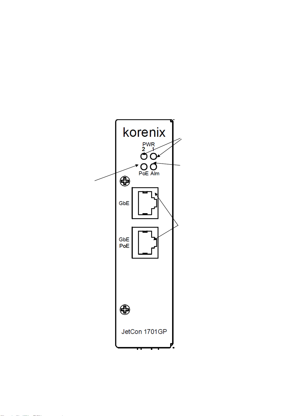
2-2. Front Panel
The Front Panel of the JetCon 1701GP-U Industrial Gigabit PoE
injector is shown in Figure A
Figure A
Power LED
Gigabit RJ-45 for
10/100/1000 Mbps
Alarm Relay Indicator
LED for PoE
8
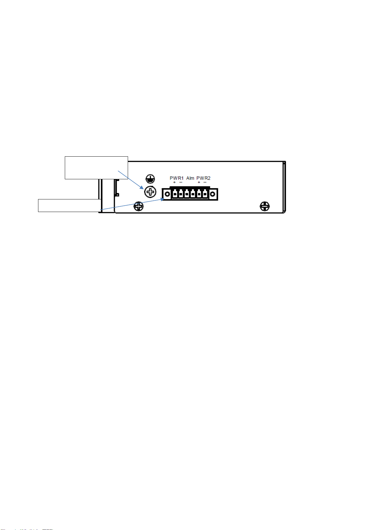
2-3. Bottom View
The bottom side of the JetCon 1701GP-U includes one 6-pin removable
terminal block connector.
The power range of JetCon 1701GP-U is from DC 44~57V with redundancy
and polarity reverse function.
To prevent interference and get better performance, it is strongly
suggest make a well earth grounding by the “Earth Ground Screw”.
Earth Ground
Screw
Terminal Block

9
2-4. Wiring the DC Power Inputs
Follow the steps below to wire JetCon 1701GP-U redundant DC power inputs.
[Note] The suitable electric wire ranges from 12 to 23 AWG.
1.
Insert the positive and negative wires into the V+ and V- contactsrespectively
of the terminal block connector
2.
Tighten the wire-clamp screws to prevent the DC wires from being loosened.
3.
The Power 1 and Power 2 support power redundancy and polarityreverse
protection functions.
4.
It accepts positive or negative power system input, but Power 1 and Power2
have to apply the same mode.

10
2-5. Connect the Dry Relay Output
JetCon 1701GP-U provides one dry relay output for fault power event.
The relay conductor ability is 24W when it connects with a DC 24V power source
and maximum current is 1A. In the following diagram shows how to make an alarm
circuit.
About the relay function, please refer section 4-4
2-6. LED Indicators
The front panel of JetCon 1701GP-U includes 2 Power LEDs, 1 LED for
Alarm Relay , 1 LED for PoE. Following table gives descriptions of the
function for each LED indicator.

11
LED
Status
Description
Power 1
Green On
Power 1 is supplying DC power.
Off
No power is being supplied.
Power 2
Green On
Power 2 is supplying DC power.
Off
No power is being supplied.
PoE
Amber On
Output power is supplied
Amber Off
No output power
Alarm
Red on
PW1 or PW2 is disconnect.
Off
PW1 and PW2 Power Connect
Table 1
2-7. Ports
Fig A. Straight through Cabling
Schematic for 10/100Mbps
Fig. C Straight through cable
schematic for 1000Mbps
Fig B. Cross Over Cabling
Schematic for 10/100Mbps
Fig. D Cross over cable
schematic for 1000Mbps

12
3. Mounting Installation
3-1. DIN-Rail Mounting
The DIN-Rail clip is already attached on the rear side of JetCon 1701GP-U. JetCon
1701GP-U supports EN 50022 standard DIN Rail, in the following diagram includes
the dimension of EN 55022 DIN Rail for your reference.
The DIN rail should behind the
spring when install the JetCon
1701GP-U onto the standard DIN
Rail.
Follow the steps below to mount
the JetCon 1701GP-U to the
DIN-Rail track.
1.Insert the upper end of the
DIN-Rail clip into the back of
the DIN-Rail track from its
upper side
2.Lightly push the bottom of the
DIN-Rail clip into the track.
3.Check if the DIN-Rail clip is
tightly attached to the track.
4.To remove the JetCon
1701GP-U from the track,
reverse the steps above.

13
4. System Configuration
The JetCon 1701GP-U provides Ethernet signal transfer function from
electrical to optical and various packet handling and cable diagnostic features.
In this chapter, we will introduce how to configure those functions and benefits as
following topics.
4-1. Event Alarm Relay Configuration
4-1. Event Alarm Relay Configuration
The connection of Event Alarm Relay already described in section 2-5 Connect
the Dry Relay output.

14
5. System Installation
.
5-1. Installation and Testing
1.
Take out your JetCon 1701GP-U Industrial Gigabit PoE Injector from the
package box.
2.
Check if the DIN-Rail clip is attached to the JetCon 1701GP-U. If the DIN-Rail
clip is not attached to the JetCon 1701GP-U, refer to DIN-Rail Mounting
section for DIN-Rail installation.
3.
To place the JetCon 1701GP-U on the DIN-Rail track or wall, refer to the
Mounting Installation section.
4.
Pull the terminal blocks off the JetCon 1701GP-U and wire the power lines.
Refer to the Wiring the DC Power Inputs section for how to wire the power
inputs.
5.
PWR1 and PWR2 dual power inputs can be connected to power sources
simultaneously. When the primary power source fails (the default setting is
PWR1), the system will automatically switch to the secondary power source
(PWR2), preventing any power interruption.
Both of Power 1 and Power 2 support positive electricity electricity power
system. Please notice the power system for power 1 and power 2 only accept
positive electricity power system at one time
6.
Check the LEDs of PWR1 and PWR2 to make sure that JetCon 1710GP-U is
operating normally.
7.
Use Category 5e straight through Ethernet cables with RJ-45 connectors to
connect network devices.
8.
Connect one side of an Ethernet cable with a RJ-45 connector to the JetCon
1701GP-U’s Ethernet port (RJ-45 port), and the other side of the ethernet cable
15
to the network device’s Gigabit ethernet port.
9.
Check the LED indicator of port status (blinking green) on the JetCon 1701GP-
U to see if the network connection is successfully established. Power on the
PC host, activate the Command Line mode, and ping the connected Ethernet
device to see if it responds.
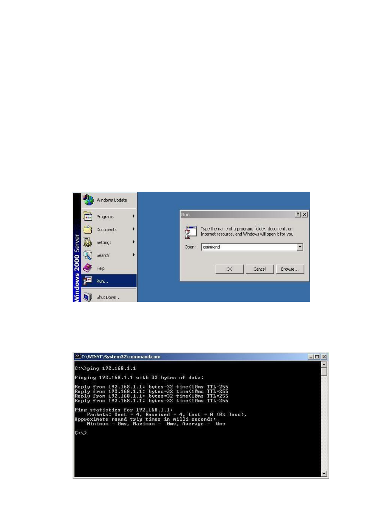
9.1
To enable the “Command Line mode”, click Run in the Start menu, type
Command, and click OK to continue.
10.
10.1
Type ping 192.168.1.1 command to check the connection. Here we use IP
address 192.168.1.1 as an example. Before the testing, be sure your PC
host and target device are in the same subnet.

16
11.
Power on the host, activate the Command Line mode, and ping theconnected
Ethernet device by typing “ping –t 192.168.1.1” command to see if it will
respond.
12.
The parameter-”t” allow you to continue to ping the network device, as shown
in the figure below.
Before you continue, make sure that both PWR1 and PWR2 are successfully
connected to power sources. When PWR1 fails, the LED for PWR1 will go out. At
that moment, if the ping command is still replying, then it proves that redundant
power input function works normally.
13.
Exit the Command Line mode, and connect PWR1 power input. At this stage,
your JetCon 1701GP-U has been tested and the installation is completed.

17
6. Troubles shooting
Make sure you are using the correct DC power suppliers (DC44~57 V) or
power adapters.
Select Ethernet cables with specifications suitable for your applications to set
up your systems. Ethernet cablesare categorized into unshielded twisted-pair
(UTP) and shielded twisted-pair (STP) cables. Category 3, 4, 5 Ethernet cables
are suitable for systems with 10 Mbps transmission speed. For systems with
100/1000 Mbps transmission speed, Category 5, 5e, 6 Ethernet cables are the
suitable specifications for this environment. Also make sure that the distance
between each node cannot be longer than 100 meters (328 feet).
If the power LEDs goes off as the power cord plugged in, a power failure might
occur. Check the power output connection to see if there is any error at the
power source. If you still cannot solve the problem, contact your local dealer
for assistance

18
7. Technical Specifications
Technology
Standard
IEEE 802.3af Power over Ethernet
IEEE 802.3at High Power PoE+
IEEE 802.3bt High Power PoE++
Performance
Forwarding
Technology
Store and Forward technology with 64~10K bytes packet forwarding ability
Event Alarm
relay alarm output for power events
PoE forwarding
conductor
RJ-45: V-(1,2), V+ (3,6) for IEEE802.3 af/at
RJ-45: V-(1,2,7,8), V+ (3,6,4,5) for IEEE802.3 bt(draft 2.0)
PoE forwarding
capability
PoE Port: 15W/IEEE802-3af, 30W/IEEE 802.3at.
60W/IEEE802.3bt,90W/IEEE802.3bt
PoE System Power Budget: 90W at 75°C Ambient temperature
Interface
Ethernet Port –RJ-45
Data-port : 1 x 10/100/1000 Base-TX
PSE-port : 1 x 10/100/1000 Base-TX
Alarm Contact
1 relay output with current carrying capacity of 1 A @ 24 VDC
Terminal block: 4-Pin for redundant power input; 2-Pin for alarm relay output.
Cables
RJ-45 Connector: 4 pairs of Cat-5e UTP/STP cable
Arrangement for 1000Base-T.
Diagnostic LEDs
System:
- 2 x Power (Green): On (Power On), Off (Power Off)
- 1 x Alarm (Red): On (Disconnect), Off (Connected)
- 1 x Power over Ethernet (Green): On (PD Detect), Off (None-Detect)
Power Connector
Removable Terminal Block: 44-57V power Input
Power Requirement
Power
Removable Terminal Block: 44-57V power Input
IEEE 802.3bt 90W PoE application: DC 52-57V
IEEE 802.3bt 60W PoE application: DC 52-57V
IEEE 802.3at 30W PoE application: DC 50-57V
IEEE 802.3af 15.4W PoE application: DC 44-57V
Power input with polarity reverse correction and over current protection.
Power Consumption
2.5Watts/ DC 48V (without PoE loading)
Mechanical
Enclosure Protection
Ingress Protection code –31
Case
Slim metal case
Mounting
DIN Rail
Dimension
99(D) x30(W)x 120(H) mm (Without Din-rail kit)
Environmental
Operating
Temperature
-40℃~75℃
Operating Humidity
0% ~ 95% non-condensing

19
Approvals
EMI
CE/EN 55032 class A, FCC Class A, EN 61000-3-2 :2014, EN 61000-3-3,
EN 61000-6-4, EN50121-4 (Compliance)
EMS
CE/ EN 55024, EN 61000-6-2, IEC 61000-4-2,IEC 61000-4-3, IEC 61000-4-4,
IEC 61000-4-5, IEC 61000-4-6, IEC 61000-4-8, IEC 61000-4-11
Shock
IEC60068-2-27 (Compliance)
Vibration
IEC60068-2-6 (Compliance)
Free Fall
IEC60068-2-32 (Compliance)
Warranty
5 years
Ordering Information
JetCon 1701GP-U
Industrial Gigabit PoE Injector
Includes
1 x JetCon 1701GP-U Industrial one-port PoE Gigabit Injector
1 x Quick Installation Guide

20
Revision History
Edition
Date
Modifications
V1.0
16-Apr,2018
New edition
V1.1
1-Nov. 2019
Correct Spec.
Table of contents
Other Beijer Electronics Media Converter manuals

Beijer Electronics
Beijer Electronics BoX2 extreme User manual

Beijer Electronics
Beijer Electronics 100-0973 User manual

Beijer Electronics
Beijer Electronics BoX2 base v2 Instruction sheet

Beijer Electronics
Beijer Electronics BoX2 extreme User manual

Beijer Electronics
Beijer Electronics BoX2 pro User manual


