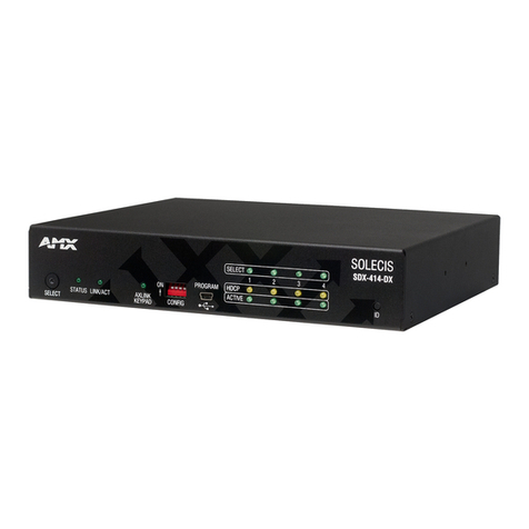
Beijer Electronics JetNet 6228G Series User manual

Page 1 of (44)
JetNet 6228G Series Installation Guide
Industrial 28-port L2
Managed Ethernet Switch
JetNet 6228G Series
Installation Guide

JetNet 6228G Installation Guide
Page 2 of (44)
JetNet 6228G Series Installation Guide
DOCUMENT CHANGE SUMMARY

JetNet 6228G Installation Guide
Page 3 of (44)
JetNet 6228G Series Installation Guide
⚫
Copyright, Trademark, and Proprietary Rights Information
©2023 Beijer Electronics All rights reserved.
No part of this content may be reproduced in any form or by any means or used to make any
derivative work (such as translation, transformation, or adaptation) without written permission from
Beijer Electronics and/or its affiliates ("Beijer"). BEIJER reserves the right to revise or change this
content from time to time without obligation on the part of BEIJER to provide notification of such
revision or change.
⚫
Disclaimer
THIS CONTENT AND ASSOCIATED PRODUCTS OR SERVICES ("MATERIALS"), ARE PROVIDED "AS IS" AND
WITHOUT WARRANTIES OF ANY KIND, WHETHER EXPRESS OR IMPLIED. TO THE FULLEST EXTENT
PERMISSIBLE PURSUANT TO APPLICABLE LAW, BEIJER DISCLAIMS ALL WARRANTIES, EXPRESS OR
IMPLIED, INCLUDING, BUT NOT LIMITED TO, IMPLIED WARRANTIES OF MERCHANTABILITY AND FITNESS
FOR A PARTICULAR PURPOSE, TITLE, NON-INFRINGEMENT, FREEDOM FROM COMPUTER VIRUS, AND
WARRANTIES ARISING FROM COURSE OF DEALING OR COURSE OF PERFORMANCE. BEIJER does not
represent or warrant that the functions described or contained in the Materials will be uninterrupted
or error-free, that defects will be corrected, or are free of viruses or other harmful components.
BEIJER does not make any warranties or representations regarding the use of the Materials in terms
of their completeness, correctness, accuracy, adequacy, usefulness, timeliness, reliability or
otherwise. As a condition of your use of the Materials, you warrant to BEIJER that you will not make
use thereof for any purpose that is unlawful or prohibited by their associated terms of use.
⚫
Limitation of Liability
IN NO EVENT SHALL BEIJER, BEIJER AFFILIATES, OR THEIR OFFICERS, DIRECTORS, EMPLOYEES,
AGENTS, SUPPLIERS, LICENSORS AND THIRD PARTY PARTNERS, BE LIABLE FOR ANY DIRECT, INDIRECT,
SPECIAL, PUNITIVE, INCIDENTAL, EXEMPLARY OR CONSEQUENTIAL DAMAGES, OR ANY DAMAGES
WHATSOEVER, EVEN IF BEIJER HAS BEEN PREVIOUSLY ADVISED OF THE POSSIBILITY OF SUCH
DAMAGES, WHETHER IN AN ACTION UNDER CONTRACT, TORT, OR ANY OTHER THEORY ARISING FROM
YOUR ACCESS TO, OR USE OF, THE MATERIALS. Because some jurisdictions do not allow limitations
on how long an implied warranty lasts, or the exclusion or limitation of liability for consequential or
incidental damages, some of the above limitations may not apply to you.

JetNet 6228G Installation Guide
Page 4 of (44)
JetNet 6228G Series Installation Guide
⚫
Trademarks
BEIJER, the BEIJER logo, and JetNet are trademarks of Beijer Electronics and/or its affiliates. Wi-Fi
Alliance, Wi-Fi, the Wi-Fi logo, the Wi-Fi CERTIFIED logo, Wi-Fi Protected Access (WPA), the Wi-Fi
Protected Setup logo, and WMM are registered trademarks of Wi-Fi Alliance. Wi-Fi Protected Setup™,
Wi-Fi Multimedia™, and WPA2™ are trademarks of Wi-Fi Alliance. All other trademarks are the
property of their respective owners.

JetNet 6228G Installation Guide
Page 5 of (44)
JetNet 6228G Series Installation Guide
Contents
I. Safety Instruction..............................................................................................8
I.I. Symbols .......................................................................................................8
I.II. Safety Notes .................................................................................................8
I.III. Certification ................................................................................................9
1.1. Introduction ........................................................................................ 10
Overview............................................................................................ 10
Main Features ...................................................................................... 10
Switch Models ...................................................................................... 11
1.2. Technical Specifications ......................................................................... 12
JetNet 6288G Series Specifications............................................................ 12
1.3. Front Panel ......................................................................................... 15
JetNet 6228G-4F-AC.............................................................................. 15
JetNet 6228G-4F-2DC ............................................................................ 16
JetNet 6228G-4F-AC-2DC ........................................................................ 17
Front Panel LEDs .................................................................................. 18
1.4. Rear Panel .......................................................................................... 19
1.5. Dimensions.......................................................................................... 20
2.1. Electrical Safety Information.................................................................... 21
2.2. Environment and Enclosure Guidelines ....................................................... 21
2.3. Package Contents.................................................................................. 22
2.4. Validating Operational Function................................................................ 22
2.5. Installing the Switch .............................................................................. 22
Installation Requirements ....................................................................... 22
Installing Guidelines .............................................................................. 23
Installing on a Rack ............................................................................... 24

JetNet 6228G Installation Guide
Page 6 of (44)
JetNet 6228G Series Installation Guide
Connecting the Rack-Mount Brackets ......................................................... 25
Mounting a Switch in a Rack................................................................... 25
Connecting Ethernet Cables..................................................................... 26
Ethernet Cable Wiring .......................................................................... 27
Data and Power Ports........................................................................... 28
Connecting a Serial Cable........................................................................ 29
Connecting and Disconnecting SFP Modules.................................................. 30
Before you Begin ................................................................................ 30
Connecting a 1000BASE-T SFP Module ...................................................... 30
Disconnecting an 1000BASE-T SFP Module ................................................. 33
Connecting Power Inputs ........................................................................ 35
Overview.......................................................................................... 35
Considerations ................................................................................... 35
Grounding the Device .......................................................................... 36
Connecting AC Power Input ................................................................... 37
Connecting DC Power Inputs .................................................................. 38
Power Supply Specifications .................................................................. 40
Connecting Digital Output Wires ............................................................... 41
3.1. Before You Begin .................................................................................. 42
3.2. Accessing the Web Interface .................................................................... 42
3.3. Changing Passwords............................................................................... 43

JetNet 6228G Installation Guide
Page 7 of (44)
JetNet 6228G Series Installation Guide
Important Notes
•
Solid state equipment has operational characteristics differing from those of electromechanical
equipment.
•
Safety Guidelines for the Application, Installation and Maintenance of Solid-State Controls
describes some important differences between solid state equipment and hard-wired
electromechanical devices.
•
Because of this difference, and also because of the wide variety of uses for solid state
equipment, all persons responsible for applying this equipment must satisfy themselves that
each intended application of this equipment is acceptable.
•
In no event will Beijer Electronics be responsible or liable for indirect or consequential
damages resulting from the use or application of this equipment.
•
The examples and diagrams in this manual are included solely for illustrative purposes.
Because of the many variables and requirements associated with any particular installation,
Beijer Electronics cannot assume responsibility or liability for actual use based on the
examples and diagrams.
✓
A Caution symbol indicates a potentially hazardous situation which, if not avoided, may
result in minor or moderate injury and or damage to the device.
Read the following Instructions:
•Keep vibrations away from it.
•Products should be used in environments with a pollution index of less than 2.
•Ensure that the installation environment does not exceed 85% humidity.
✓
A Warning symbol indicates a hazardous situation which, if not avoided, could result in
damage to the device, death or serious injury.
Read the following Instructions:
•In order to prevent electric arcs, never assemble or wire the products with power applied.
Otherwise, it may result in unexpected and potentially dangerous actions by field devices.
Arching poses an explosion risk in hazardous locations. Before assembling or wiring the
modules, ensure that the area is non-hazardous or that the system power has been removed
accordingly.
•Check the rated voltage and terminal array before wiring. Avoid environments over 50℃of
temperature. Avoid placing it directly in the sunlight.

JetNet 6228G Installation Guide
Page 8 of (44)
JetNet 6228G Series Installation Guide
•Ensure that inputs and outputs are made according to the module specification. Wire the
system using standard cables.
•In order to avoid an electric shock or malfunction, do not touch any terminal blocks or IO
modules while the system is running.
•Keep away from the strange metallic materials not related to the unit and wiring works
should be controlled by the electric expert engineer. Else it may cause the unit to a fire,
electric shock or malfunction.
•Modules should not be placed near inflammable materials. A fire may result if it is not
handled properly.
I. Safety Instruction
I.I. Symbols
A Caution symbol indicates a potentially hazardous situation to you.
A Warning symbol indicates situations that can be potentially lethal or extremely
hazardous to you.
An Attention symbol indicates potential damage to programs, devices, or data.
Identifies information that is critical for successful application and understanding
of the product.
I.II. Safety Notes
The modules are equipped with electronic components that may be destroyed by
electrostatic discharge. When handling the modules, ensure that the environment
(persons, workplace and packing) is well grounded. Avoid touching conductive
components, M-bus and Hot swap-bus pin.

JetNet 6228G Installation Guide
Page 9 of (44)
JetNet 6228G Series Installation Guide
I.III. Certification
Note! For specific information relating to certification of this module type, see the separate
certification document summary.
The following certification information applies to JetNet 6228G series models:
⚫
CE compliance
⚫
FCC compliance

JetNet 6228G Installation Guide
Page 10 of (44)
JetNet 6228G Series Installation Guide
Chapter 1. Switch Overview
1.1. Introduction
Overview
The JetNet 6228G series includes 19-inch L2 full Gigabit industrial rackmount switches designed for
applications that require high-speed connectivity. With full Gigabit capability, the JetNet 6228G
series increases bandwidth to provide high performance and the ability to quickly transfer large
amounts of video, voice, and data across a network.
Moreover, the JetNet 6228G series supports harsh environments at -40°C to 75°C and is designed
with an industrial EMC grade to ensure proper operation. Also, the JetNet 6228G series has various
cyber security and cyber redundancy features, as well as isolated redundant power supplies.
This JetNet 6228G series is ideal for many applications, including transportation, surveillance, and
automation.
Main Features
The Beijer JetNet 6228G Series, industrial 28-port L2 managed Ethernet switches, features include:
•Rackmount switch with full GbE L2 support
•USB-based firmware upgrading
•Multiple redundancy protocols such as MSR, MSTP, and RSTP are supported
•Isolated redundant power inputs with VDC or 110/220 VAC power
•Compliant with EN50121-4
•Fanless operation from -40°C to 75°C (-40°F~167°F)

JetNet 6228G Installation Guide
Page 11 of (44)
JetNet 6228G Series Installation Guide
Switch Models
The JetNet 6228G series is available in the following models: JetNet 6228G-4F-AC,
JetNet 6228G-4F-2DC, and JetNet 6228G-4F-AC-2DC. The following figures depict the models.
Switch Model
Description
Image
JetNet 6228G-4F-AC
Industrial 28-port Full Gigabit with 4-
port SFP Managed Ethernet Switch,
AC input
JetNet 6228G-4F-2DC
Industrial 28-port Full Gigabit with 4-
port SFP Managed Ethernet Switch,
Dual DC Inputs
JetNet 6228G-4F-AC-2DC
Industrial 28-port Full Gigabit with 4-
port SFP Managed Ethernet Switch,
AC and Dual DC Input
Packing
Includes:
•JetNet 6228G
•Rackmount kit
•Quick Installation Guide
Note: Please download the User Manual from the website.

JetNet 6228G Installation Guide
Page 12 of (44)
JetNet 6228G Series Installation Guide
1.2. Technical Specifications
JetNet 6288G Series Specifications
Specifications
Description
Interface
RJ-45 Port
24 x 10/100/1000 Mbps
SFP Port
4 x 100/1000 Mbps
Console Port
RS-232 (RJ-45 connector)
Storage
USB (Type A)
Performance
Switch Technology
Store and Forward technology with 56 Gbps switch
fabric
CPU Performance
1.2GHzs ARM Cortex-A9 processor
System Memory
128 MB NOR flash, 1GB system RAM
Transfer packet Size
Up to 9K bytes Jumbo Frame
MAC address Table
16K
Packet Buffer
512 KB
Transfer Performance
14,880 pps for Ethernet; 148,800 pps for Fast Ethernet;
1,488,100 pps for Gigabit Ethernet
Technology
Standard
•IEEE 802.3 10Base-T
•IEEE 802.3u 100Base-TX
•IEEE 802.3ab for 1000BaseT(X)
•IEEE 802.3z Gigabit Ethernet Fiber
•IEEE 802.3x Flow Control and Back Pressure
•IEEE 802.1AB Link Layer Discovery Protocol (LLDP)
•IEEE 802.1Q VLAN and GVRP
•IEEE 802.1D:2004 Rapid Spanning Tree (RSTP)
•IEEE 802.1s Multiple Spanning Tree Protocol (MSTP)
•IEEE802.3ad Link Aggregation Control Protocol
(LACP)
•IEEE 802.1x Port Based Network Access Control
•IEEE 802.1p class of service
Configuration,
monitoring interface
•SNMP V1/V2c/V3 with SNMP Trap (4 Trap Stations),
RMON Group 1
•Local RJ-45/RS-232 connector with Cisco like
command
•USB Firmware upgrade

JetNet 6228G Installation Guide
Page 13 of (44)
JetNet 6228G Series Installation Guide
Specifications
Description
System Manage Secure
•Telnet/Local Console support command like
interface with Cisco like commands.
•Management Device Login Switch System by Remote
RADIUS /TACACS+ account/password, key for RADIUS
Server authentication
Management Utility
Management utility with IEEE 802.1AB Link Layer
Protocol for Device finding and Link Topology Discovery
Network Time Protocol
NTP protocol with daylight saving and localize time sync
System Log
Local or remote log server with authentication
Alarm
1 alarm set, current carrying capability of 1A@24V
Power (PWR1, PWR2, PWR3) failure
Network
Performance
Port Configuration
Port Link Speed, Link Mode, Link Status and Port
Port Trunk/ Link
IEEE 802.3ad port aggregation and static port trunk,
maximum 8 trunk groups
VLAN
IEEE 802.1Q tag VLAN with 4K VLAN/GVRP entries VLAN
ID Range: 1-4094
Class of Service
IEEE 802.1p class of service, 8 priority queues/port
Traffic Prioritize
Supports 8 physical queues with weighted fair queuing
(WRR) or Strict Priority Schemer, which follows IEEE
802.1p CoS tag and IPv4 Type of Service/Differ
information to prioritize the traffic of your industrial
network
IGMP Snooping
IGMP Snooping v1/v2 for multicast filtering and IGMP
Query mode, supports unknown multicast forwarding
policies- Drop, Flooding and Forward to route port Max
256 groups
Rate Control
Egress rate limit
Port Mirroring
One-to-one traffic mirror monitoring
DHCP
DHCP Client/Server with IP & MAC address binding
Advanced Cyber
Security
IEEE 802.1x, DHCP Snooping, Access Control List (ACL),
TACACS+
Network
Redundancy
Ring Redundancy
Multiple Super RingTM Technology, Includes Rapid Super
Ring, Rapid Dual Homing, SuperChainTM
Rapid Dual Homing
Multiple uplink paths to one or multiple upper Switch.
SuperChainTM
Flexible, scalable ring technology, compatibility, and
easy configurable: Border Switch and Member Switch
Rapid Spanning Tree
IEEE 802.1D-2004 Rapid Spanning Tree Protocol.
Compatible with Legacy Spanning Tree and IEEE 802.1w

JetNet 6228G Installation Guide
Page 14 of (44)
JetNet 6228G Series Installation Guide
Specifications
Description
Multiple Spanning Tree
IEEE 802.1s Multiple Spanning Tree, each MSTP instance
can include one or more VLANs, and also supports
multiple RSTP deployed in a VLAN or multiple VLANs
Power
Requirement
AC Power Input
110/220 VAC (100-240VAC)
DC Power Input
2 x 18-75VDC
Power Consumption
16.32W (48VDC), 34.56W (240VAC)
Mechanical
Installation
19” 1U Rackmount
Enclosure Material
Steel Metal
Dimension (H x W x D)
43.8 x 431 x 375 mm
17.24 x 16.976 x 14.77 in.
Weight
7.4kg (16.31 lbs) with package
Ingress Protection
Robust IP40
Environmental
Operating
Temperature
-40°C~75°C (-40°F ~ 167°F)
Operating Humidity
10%~95%, Non-Condensing
Storage Temperature
-40°C~85°C (-40°F ~ 185°F)
Hi-Pot Insulation
AC 1.5KV for Ethernet Interface to Power, Power to
Case
Regulation
Rail Traffic
EN50121-4
EMC
•FCC Class A, CE
•EN 50121-4
•EN 61000-6-4
•EN IEC 61000-3-2
•EN 61000-3-3
•EN 61000-4-2
•EN 61000-4-3
•EN 61000-4-4
•EN 61000-4-5
•EN 61000-4-6
•EN 61000-4-8
•EN 61000-4-9
Vibration
IEC 60068-2-6, IEC 60068-2-36
Shock
IEC 60068-2-27
Free Fall
IEC 60068-2-32
MTBF
570,639 hrs
Warranty
5 Years
* Maximum power consumption values are measured under a 100% load test and should be used as
estimates.

JetNet 6228G Installation Guide
Page 15 of (44)
JetNet 6228G Series Installation Guide
1.3. Front Panel
Described in this section are the front panel components of the JetNet 6228G series switches.
JetNet 6228G-4F-AC
The LEDs and ports are located on the front panel of the switch as illustrated in the following
illustrations.
Figure 3 Front Panel of 28-Port JetNet 6228G-4F-AC
No.
Item
Description
1.
RJ-45 console port
Console/Terminal Port (RJ45) for device management/debug
2.
LNK / ACT LED
See Front Panel LEDs on page 18 for further details.
3.
Speed LEDs
See Front Panel LEDs on page 18 for further details.
4.
SFP module slot
SFP ports enable the switch to communicate with other switches
through modules.
5.
SFP LEDs
See Front Panel LEDs on page 18 for further details.
6.
24 Gigabit ports
Multigigabit Ethernet ports support speeds of 100 Mbps and 1
Gbps on Cat 5e cables.
7.
System LEDs
See Front Panel LEDs on page 18 for further details.
8.
USB Type A port
USB ports connect to USB devices for restoring firmware images.

JetNet 6228G Installation Guide
Page 16 of (44)
JetNet 6228G Series Installation Guide
JetNet 6228G-4F-2DC
The LEDs and ports are located on the front panel of the switch as illustrated in the following
illustrations.
Figure 3 Front Panel of 28-Port JetNet 6228G-4F-2DC
No.
Item
Description
1.
RJ-45 console port
Console/Terminal Port (RJ45) for device management and debug
2.
LNK / ACT LED
See Front Panel LEDs on page 18 for further details.
3.
Speed LEDs
See Front Panel LEDs on page 18 for further details.
4.
SFP module slot
SFP ports enable the switch to communicate with other switches
through modules.
5.
SFP LEDs
See Front Panel LEDs on page 18 for further details.
6.
24 Gigabit ports
Multigigabit Ethernet ports support speeds of 100 Mbps and 1
Gbps on Cat 5e cables.
7.
System LEDs
See Front Panel LEDs on page 18 for further details.
8.
USB Type A port
USB ports connect to USB devices for restoring firmware images.

JetNet 6228G Installation Guide
Page 17 of (44)
JetNet 6228G Series Installation Guide
JetNet 6228G-4F-AC-2DC
The LEDs and ports are located on the front panel of the switch as illustrated in the following
illustrations.
Figure 3 Front Panel of 28-Port JetNet 6228G-4F-AC-2DC
No.
Item
Description
1.
RJ-45 console port
Console/Terminal Port (RJ45) for device management and debug
2.
LNK / ACT LED
See Front Panel LEDs on page 18 for further details.
3.
Speed LEDs
See Front Panel LEDs on page 18 for further details.
4.
SFP module slot
SFP ports enable the switch to communicate with other switches
through modules.
5.
SFP LEDs
See Front Panel LEDs on page 18 for further details.
6.
24 Gigabit ports
Multigigabit Ethernet ports support speeds of 100 Mbps and 1
Gbps on Cat 5e cables.
7.
System LEDs
See Front Panel LEDs on page 18 for further details.
8.
USB Type A port
USB ports connect to USB devices for restoring firmware images.

JetNet 6228G Installation Guide
Page 18 of (44)
JetNet 6228G Series Installation Guide
Front Panel LEDs
The system LEDs are used to monitor the switch activity and performance.
Figure 3 Front Panel LEDs of 28-Port JetNet 6228G Series
No.
Item
Description
1.
Power LED
AC: Available only on AC models.
Solid green: Device is powered on.
Off: Device is powered off
2.
Power LED
DC1 / DC2: Available only on DC models.
Solid green: Device is powered on.
Off: Device is powered off
3.
Alarm
Solid red: Alarm trigger enabled
Off: Alarm is not triggered, no failure detected
4.
R.S.
Ring Status indicator
Solid green: Ring failure detected
Off: No failure detected
5.
System
Solid green: System is enabled
Off: System is powered off, failure, or in boot up process
6.
SFP port
Solid green: Link established
Flashing green: Packet transmitting/receiving
Off: No Ethernet link or link speed 100Mbit/s
Solid amber: Link speed 1 Gbit/s
7.
Link / Act
Solid amber: Ethernet link established
Flashing amber: Packet transmitting/receiving
Off: Link is inactive
8.
Speed (Gigabit),
status
Solid green: Connection established to the port, 1000 Mbps link
established
Off: Connection speed is under 1000 Mbps or no connection

JetNet 6228G Installation Guide
Page 19 of (44)
JetNet 6228G Series Installation Guide
1.4. Rear Panel
The power inputs and relay connectors are located on the rear panel of the switch as illustrated in
the following illustrations.
Figure 3 Rear Panel of 28-Port JetNet 6228G Series
No.
Item
Description
1.
AC power socket
AC socket available only on AC models.
Connect the switch to AC power.
2.
LNK / ACT LED
See Front Panel LEDs on page 18 for further details.
3.
DC power socket
DC socket available only on DC models.
Wire for DC power source. The switch requires 18-75VDC,
max 1A power source.
4.
Ground terminal
Connect to a ground source to provide local earth potential.

JetNet 6228G Installation Guide
Page 20 of (44)
JetNet 6228G Series Installation Guide
1.5. Dimensions
The power inputs and relay connectors are located on the rear panel of the switch as illustrated in
the following illustrations.
Note! For demonstration purposes, the Dimensions view illustrates a single JetNet 6288G model.
Figure 3 Dimensions of 28-Port JetNet 6228G Series
This manual suits for next models
6
Table of contents
Other Beijer Electronics Switch manuals

Beijer Electronics
Beijer Electronics korenix JetNet 3018G User manual
Beijer Electronics
Beijer Electronics korenix JetNet 5020G User manual
Beijer Electronics
Beijer Electronics JetWave 2714GF Series User manual
Beijer Electronics
Beijer Electronics Korenix JetNet 6728G Series User manual
Beijer Electronics
Beijer Electronics korenix JetNet 3008 Series User manual
Beijer Electronics
Beijer Electronics Korenix JetNet 6528Gf Series User manual
