BEINAT BX280 User manual

Belonging to
Important: Assembly / maintenance of the appliance must be carried out by qualified personnel and in
accordance with applicable laws and regulations.
The manufacturer assumes no responsibility for the use of products that have to comply with particular
environmental and / or installation standards.
Importantnote
Before connecting the equipment, it is recommended that you read the instruction manual carefully and keep
it for future reference. It is also recommended to perform the electrical connections correctly as per enclosed
drawings, observing the instructions and the Standards.
N.B. Refer to the documentation in all cases where the symbol ison the side
Channel: Beinat gas solutions
Electricconnections alsoavailable on
CONFORMITY
Installation
and user guide
INSTALL IN SAFE
AREA, NO ATEX
EN50194
EN 45544-1-3
EN 50270
EN 61010-1
Compliant EN 60079-29-1
Installation EN60079-29-2
Reports issued by TUV Italia
Control Unit from 1 to 2 Conventional sensors BX280
Rev. 10
Through the connection of 2 remote sensors, the BX280control unithasbeen designed and builtaccordingto European
regulations to detect the presence of toxic and/or explosive gas flexibly.
A microprocessor is used tocreate a complete surveillance and control system with maximum flexibility. Thanks to this
and its other features, the BX280 is suitable for civil and industrial applications.
The BX280 control unit has two danger levels:
1st LEVEL, 1st Pre-Alarm. This was set at 13 % of L.E.L. for all sensors.
2nd LEVEL, Main Alarm. This was set at 20% of L.E.L.
Other technical features make this controlunit extremely versatile and reliable; for example, by using a series of micro-
switches it is possible to:
Select or disable the probe when not installed or faulty;
Select the type of gas to be detected (toxic or explosive);
Choose the relay functioning mode (pulsed or continuous);
Choose the main alarm relay shut-down time.
A TEST button checks the efficiency of both the unit and connected probe to ensure total control of the BX280.
Thanks to the Omega-type format both small and large systems can be built by exploiting the modularity of the DIN
rail in the previously set electrical panels.
In addition to the alarm signal light, it is fitted with an internal buzzer.

Page 2
Mains Power ............................................................................................... 110/230VAC 50/60Hz ±10%
Secondary Power Through Battery max 2.2 Ah ...............................................................12,7 V ±10%
Battery Charger max 2.2 Ah ............................................................... By means of a microprocessor
PowerDemand .................................................................................................... 6 W max @ 230V
Power Demand .............................................................................................. 5 W max @ 12 V
Relay Contact Range ..............................................................................................................10A 250V
Pre Alarm ............................................................................................ Set to 13% of L.E.L. or 200ppm CO
Final Alarm ......................................................................................... Set to 20% of L.E.L. or 300ppm CO
Sensor’s faults detected by Fault Circuit .................................................. Interruption, short circuit, or wear
OVER LOAD Check .................................................................................1 for each probe and 1 for battery
Micro-switches to include or exclude the probes ............................................................................ 2 built in
Max number of probes that can be connected 2.......................... Catalityc, Electrochemical Cell, Semiconductor
Input Signal ....................................................................................................... 4 ÷ 20 mA on 220 ohm
Device Accuracy ...................................................................................................................... 1% FS
Control Unit ............................................................................................................... 8-bit microprocessor
Functioning Temperature ................................................................................................. -10°C ÷ +60°C
Waiting,blinking period ....................................................................................................... 90 seconds
Manual Test ............................................................................................................................. Built in
Max. distance between probes and unit........ ................................................................................. 100 m
Cable diameter for connecting probes ............................................................................................. 1 mm2
Connection: The cable of connection of the probe must not be installed together with the power
cables. Otherwise, make sure to use a shielded cable
Omega-type size DIN EN 50092 6 modules ................................................................................. 105*90*58
Degree of Protection .................................................................................................................... IP20
Warranty ....................................................................................... 3 years from the date of manufacturing
Precautions
CHECK the integrity of the unit after having removed it from the box.
Check that the data written on the box correspond to the type of gas used.
When doing the electrical connections, follow the drawing closely.
Any use of the detector for purposes otherthan the intended one is considered improper, and
as a result of which BEINAT S.r.l. therefore disclaims any responsibility for possibledamages
caused to people, animals or objects.
IMPORTANT: Do not test the device using the gas tap as this does not necessarily provide
sufficient concentration to activate the main alarm.
TERMS and EXPECTATIONS: The installation of the control unit, its ordinary and extraordinary maintenance, every
six months, and its out of service removal at the end of the functional life guaranteed by the manufacturer, must be
carried out by authorized or specialized personnel.
In order to achieve long and satisfactory use of your digital control unit, use it by respecting the following precautions.
Do not allow it to become wet.
The control unit can be seriously damaged as it is not waterproof either when immersed in water or exposed to high
levelsof humidity.
Do not drop it.
Heavy knocks or falls during transportation or installation can damage the appliance.
Cleaning
Never clean the device with chemical products. If necessary, wash with a moist cloth.
Technical Specifications
90 mm
45 mm
37 mm
105 mm
90 mm
45 mm
BX280 Pre
Alarm Main
Alarm
Fault
Fault
Zone2
Zone1
8 13 20 %LEL
120 200 300 ppm
Over Load
Battery Probe
Power Battery CO GAS
RESET TEST

Page 3
Main Compatible Probes
MAINTENANCE
The user periodically (every 6 months) must perform a check of the operation of the control unit by spraying
a suitable test gas at the base of the probes connected until the alarm condition is reached.
• At least once a year make a more accurate check by a specialist technician.
• Disabling the detector must be carried out by qualified personnel.
Installation of the detector does not exonerate. From the observance of all rules regarding the characteristics,
installation and use of gas appliances. The ventilation of the premises and the discharge of the combustion products
prescribed by UNI norms as from ART. 3 LAW 1083/71 and the relevant provisions of law.
SG500 Catalytic IP30 Domestic Use CH4-LPG 0÷100% LEL 4÷20 mA ±5 % NO NO
SG544 Catalytic IP44 Tertiary CH4-LPG 0÷100% LEL 4÷20 mA ±5 % NO NO
SGM595 Catalytic IP55 Tertiary See catalogue 0÷100% LEL 4÷20 mA ±5 % Yes NO
SGM595/A Catalytic IP66 Zone 2 See catalogue 0÷100% LEL 4÷20 mA ±5 % Yes NO
SGM533 Catalytic IP55 Tertiary See catalogue 0÷100% LEL 4÷20 mA ±5 % Yes Yes
SG800 Catalytic IP66 Zone 2 See catalogue 0÷100% LEL 4÷20 mA ±5 % Yes Yes
HCF100 SemiCondut IP55 Tertiary FREON 0÷300% ppm 4÷20 mA ±5 % NO Yes
SG895 Pellistor ATEX Zone 1 See catalogue 0÷100% LEL 4÷20 mA ±5 % Yes NO
SG580 Catalytic IP66 Zone 2 See catalogue 0÷100% LEL 4÷20 mA ±5 % Yes NO
SGF100 Catalytic IP64 Zone 2 Methane 0÷100% LEL 4÷20 mA ±5 % Yes Yes
SGF102 Catalytic IP64 Zone 2 LPG 0÷100% LEL 4÷20 mA ±5 % Yes Yes
SGF104 Optical Fluores IP64 Zone 2 Oxygen In % 4÷20 mA ±5 % Yes Yes
SGF106 SemiCondut IP64 Zone 2 FREON 0÷300% ppm 4÷20 mA ±5 % Yes Yes
SGF108 Elettrochimica IP64 Zone 2 H2S 0÷300% ppm 4÷20 mA ±5 % Yes Yes
SGF110 Electrochemical IP64 Zone 2 C O 0÷300% ppm 4÷20 mA ±5 % Yes Yes
SGF112 Catalytic IP64 Zone 2 Hydrogen 0÷100% LEL 4÷20 mA ±5 % Yes Yes
CO100r Electrochemical IP55 Tertiary CO 0÷300% ppm 4÷20 mA ±5 % Yes Yes
CO100Ar Electrochemical IP66 Zone 2 CO 0÷300% ppm 4÷20 mA ±5 % Yes Yes
SG800duct Catalytic IP66 Zone 2 CH4LPG 0÷100% LEL 4÷20 mA ±5 % Yes Yes
CO200duct Electrochemical IP66 Zone 2 CO 0÷300% ppm 4÷20 mA ±5 % Yes Yes
Application in:
Domestic: family accommodation. Local boilers up to 70 kW-h
Tertiary Areas: Large Rooms Boilers, Workshops, Material Deposits, Industrial Kitchens, Large Buildings, Buildings.
Zone 2 - Mixed IP66 ATEX: High probability of escape, high risk locations, premises for which applicable regulations apply.
Zone 1 - Hazardous Area, High Risk Hazards, Rooms for Which Regulations, Tanks, Control Valves are in force.
Probe Sensor Degree Suitable for Gas Range Output Precis. Calibration Relay
Protec. Detected Working Automatic
Sensor
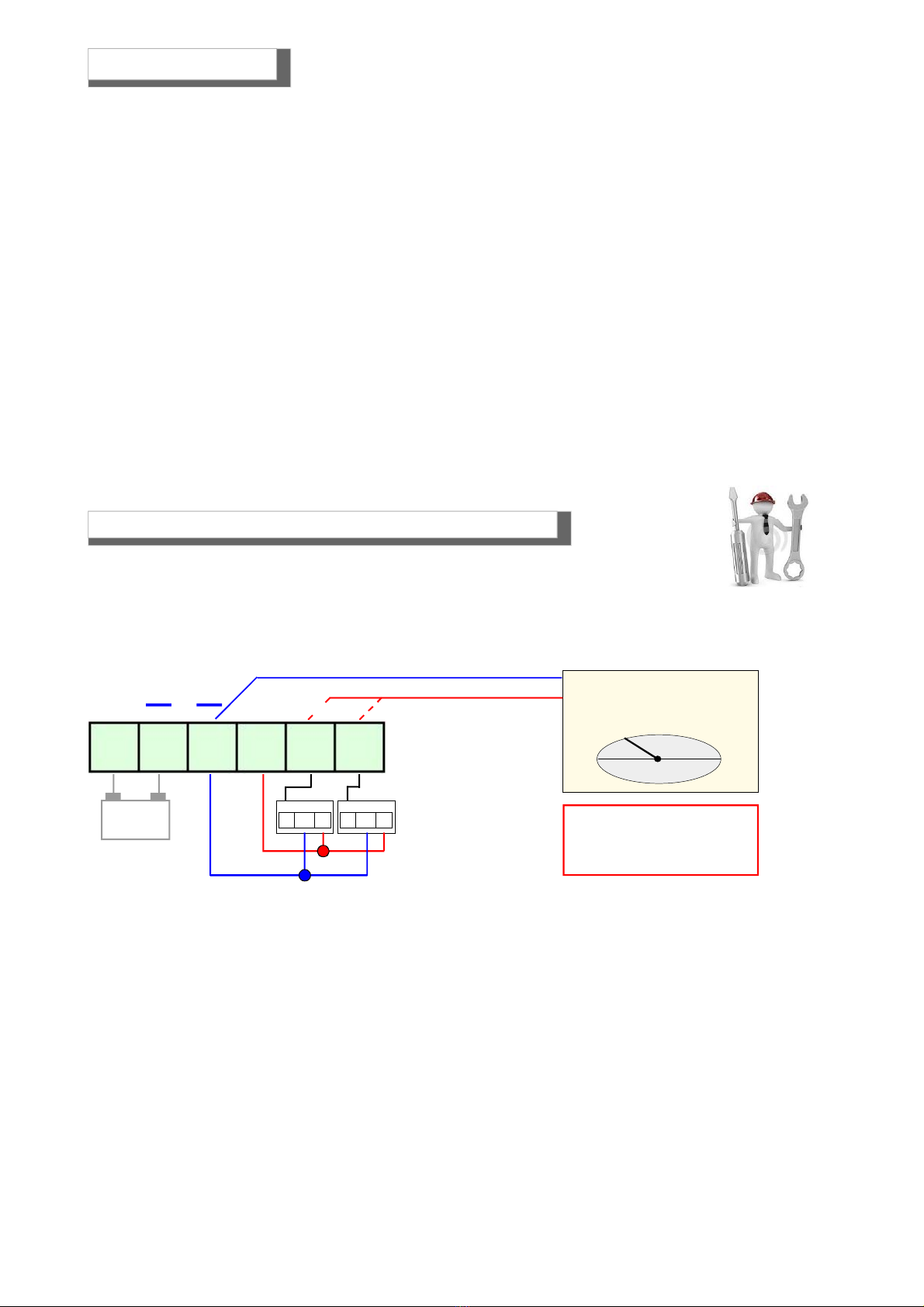
WARNING! Actions to be taken in case of alarm
Gas
1) Put out all free flames.
2) Close the main gas tap or the LPG cylinder tap.
3) Do not turn any lights on or off; do not turn on any electrical device or appliance.
4) Open windows and doors in order to increase ventilation.
If the alarm stops, its cause must be found and the relevant consequent measures taken.
If the alarm continues and the cause of gas presence cannot be found or removed, abandon the building and call
the emergency services when outside (fire department, distributors, etc.)
IMPORTANT: The operation test should not be carried out with the gas tap as this does not guarantee a sufficient
concentration to activate the general alarm.
Warning !!
If you have the following symptoms: vomiting, sleepiness, or else, go to the closest first aid station
and inform the operators that you could have been poisoned by Carbon Monoxide, or by an excess
or deficiency of oxygen

Page 4
1) MAINS LED. It lights up when electrical power is connected. Initially, this led blinks for about 1 minute and
a half waiting for the check.
When this LED is blinking the BX280 is not capable of detecting gas.
2) BATTERY LED. This LED lights up when no mains is present and the BX280 is powered by the battery. When
this led is blinking the battery is flat.
3) GAS CONCENTRATION SCALE LEDs. These leds light up in sequence according to the environment gas
concentration level increase.
a) When the first led turns on, the gas concentration level has reached 8% of LEL.
b) When the second led turns on, the gas concentration level has reached 13% of LEL and the 1st THRESHOLD
relay contact is closed.
c) When the third led turns on, the gas concentration level has reached 20% of LEL and the MAIN ALARM
relay contact is closed.
The 20% led stays on to keep the alarm zone in the MEMORY.
4) The control unit is fitted with electronic protections, called OVER LOAD, in order to prevent irreparable
damages to the unit. Therefore, if these led turns on, it does not mean the control unit is not working. But it
does mean the devices connected to it (or the corresponding connections) are faulty.
OVER LOAD LED (probe overload): If this led turns on, it means there is a short circuit or high current
absorption in the probes, and the corresponding connection cables. Please check the battery and the connection
cables.
OVER LOAD BATTERY LED (battery overload): If this led turns on, it means the battery is not connected
properly, or it has an anomalous voltage absorption. Please check the battery and the connection cables.
5) TEST BUTTON. Pressing and holding down this button, you can obtain a gas leakage simulation. This way,
all pre-alarm LEDs until the final alarm led will light up in sequence, switching the correspondent relays.
6) RESET BUTTON. This button is pressed to reset all memories.
7) TOXIC GAS selection led. This led lights up when the internal micro-switch is switched to “CO”.
8) EXPLOSIVE GAS selection led. This led lights up when the internal micro-switch is switched to “GAS”.
9) FAULT LED. This led will light up when the connected probe is faulty, if there is an interruption in the cable
connection, or if an error was made during wiring.
10) Led PRE-ALARM. When this led turns on, the gas concentration level has reached 13% of LEL and the
1st THRESHOLD relay contact is closed.
11) Led MAIN ALARM.When this led turns on, the gas concentration level has reached 20% of LEL and the
MAIN ALARM relay contact is closed.
12) These switches are used to enable or to desable the Positive Security and to select the working mode of
the relay.
13) These switches are used to include or exclude the probe and to select the type of gas, toxic or explosive.
Componentsand commands
BX280 Pre
Alarm Main
Alarm
Fault
Fault
Zone2
Zone1
8 13 20 %LEL
120 200 300 ppm
Over Load
Battery Probe
Power Battery CO GAS
RESET TEST
5 6 13 123
1
4
2
10
11
9
9
87

Page 5
Disabling or uninstalling the probes
The control unit has two micro switches one for each zone.
The switch number 1 is used to enable or disable the connected probe.
This micro-switch is also used to disable the probe in case of failure.
Selection of the type of gas monitored for each probe
The control unit has two micro switches one for each zone.
The switch number 2 is used to select reading the type of gas that the probe is connected to detect.
The LEL reading is obtained by shifting the switch to ON. Explosive gas.
The ppm reading is obtained by shifting the switch to OFF.Toxic gas.
Zone 1 Zone 2
Zone 1 Zone 2
Working mode of the relay and the main alarm
Switch 1 – Selection of the intrinsic safety
In the ON position, the positive safety function is enabled.
The relay is energized after performing the step of waiting and switches when the BX280 is main alarm
In the OFF position, the positive safety function is disabled.
The relay is energized only when the BX280 goes into the mainl alarm
Switch 2 - Working mode of the relay and the main alarm.
In the OFF (continuous) position, the relay remains closed until the RESET button is pressed.
In the ON (impulse) position, the relay remains closed for 20 seconds, and then disenergizes afterwards.
Micro-switches 1Positive safety
Micro-switches 2Working mode of the main
alarm relay
Description of Micro-switches
Micro-switch (1) to enable or disable the probe of the
desired zone.
Position ON enabled position OFF disabled
Micro-switch (2) to select the type of gas monitored of
the desired zone.
Positione ON reading in LEL - Explosive gas
In posizione OFF lettura in ppm - Toxic gas

Page 6
Power supply
230VAC
CNC
NO
CNC
NO
CNC
NO
PH N 4 5 6 7 8 9 10
Fault 1°Threshold Main Alarm
Connection of probes and eventual battery
12V
+ +
Optional
3 2 1
Probe 1 3 2 1
Probe 2
R1 R2
1 2 3 4 5 6
Diagram of the terminal block relay
BX280 Pre
Alarm Main
Alarm
Fault
Fault
Zone2
Zone1
8 13 20 %LEL
120 200 300 ppm
Over Load
Battery Probe
Power Battery CO GAS
RESET TEST
Electrical Connections
WARNING.
Before connecting to the mains power, ensure the voltage is correct.
Carefully follow the instructions andthe connections according to Regulationsinforce,keeping in mind that
the signal cables should be laid separate from the power cables.
An automatic cut-off switch (appropriately identified as devicesectioning of the detector) should be
incorporated in the electrical system, adequatelylocated and easily accessible.

Page 7
Connections of one solenoid valve Normally Closed with Positive Safety
Connections of a solenoid valve Normally Closed without Positive Safety
Connection examples
CNC
NO
CNC
NO
CNC
NO
PH N 4 5 6 7 8 9 10
Fault 1°Threshold Solenoid valve NC
Ph
N
230 VAC
CNC
NO
CNC
NO
CNC
NO
PH N 4 5 6 7 8 9 10
Fault 1°Threshold Alarm Solenoid valves
Ph
N
230 VAC
NC NA
Diode
1N 5406
Solenoid valve GAS and Sirens 12 VDC
12 V
+ +
3 2 1
Probe 1 3 2 1
Probe 2
R1 R2
1 2 3 4 5 6
Powersupply
230/12V
If a 12Vdc solenoid valve, which does not work well, is connected to the BX280.
Direct connection of 12VDC solenoid valves or sirens to the BX280 is not permitted.
An external power unit must always be used. The BX280 M gives a max current of 50mA.
Controlunitpowersupplyandconnectionof onesolenoidvalvewithsirensto12VDCtroughanalternative
source and recharge battery.

Page 8
Ph
N
CNC
NO
CNC
NO
CNC
NO
PH N 4 5 6 7 8 9 10
Fault 1°Threshold Alarm Solenoid valves
Diode
1N 5406
12 V
+ +
3 2 1
Probe 1 3 2 1
Probe 2
R1 R2
1 2 3 4 5 6
Powersupply
230/12V
Ph
N
230 VAC
230 VAC
Electrical Connections
Connections to Positive Safety disabled and an external power supply for
valve control and siren 12 V DC
If a 12Vdc solenoid valve, which does not work well, is connected to the BX280.
Direct connection of 12VDC solenoid valves or sirens to the BX280 is not permitted.
An external power unit must always be used. The BX280 M gives a max current of 50mA.

Page 9
PROBE INSTALLATION INFORMATION
Installation and positioning of the probe
The BX280 control unit belongs to group II and must be installed in a safe area;
Outside the ATEX zone, however, not in boiler rooms or engine room.
The control unit must be accessible and visible to the user.
The BX280 is designed so that it can be mounted into electrical panels.
The Control Unit complete cabinet is an equipment suitable for wall mounting and is powered by 110/240 VAC with
IP20 protection
When installing, it is good to use the normal care that an electronic equipment requires:
- Install the equipment away from excessive heat sources.
- Avoid liquids coming into contact with the control unit, remembering that its external structure has IP20 degree of
protection if installed on the Boxed version (cabinet) supplied to the source is ....
The sensors must be selected with an IP degree depending on the area to be controlled (Kitchens, Boiler
Rooms, Laboratory, etc.) by selecting one of the probes from Beinat from IP30 to ATEX. see page 3
Position of thedetection sensors
You can connect many types of remote probes to this unit. Therefore, they should be positioned at different heights
depending on the type of gas to be detected.
These heights are:
- 30 cm from the lowest point of the floor in order to detect: Heavy gases (L.P.G. etc.)
- 30 cm from the highest point of the ceiling in order to detect: light gases (Methane, etc.)
- 160 cm from the lowest point of the floor in order to detect: volatile gases (CO, etc.)
It is importanttonote that the remote probes should be installed according to the following restrictions:
1) The sensors should not be placed near the appliances to be controlled (boilers, burners, industrial kitchens, etc.)
but on the opposite side.
2) The sensors should not be affected by smoke, vapour, and moving air, as they could distort their measurement.
3) The sensors should not be placed near sources of heat, ventilators or fans.
It should be noted that the internal GAS sensors of the probe are perishable components with a variable average
life span from 5 to 6 years (you can request the relative table). Therefore, after this period of time has elapsed it
is advisable to replace them.
4) The control of operation and maintenance and / or extraordinary must be carried at least once a year. good
to keep
When turning on leds fault is necessary make the replacement of the probe by a specialized technician.
30 cm Light Gases
30 cm Heavy Gases
160 cmVolatileGases

Page 10
1) Apply power using the proper switch. This switch should be fitted with protection fuses.
2) You will notice that some LEDs will light up in turn for about 20 seconds, so as to test the LEDs.
3) The COUNTDOWN begins that lasts about 90 seconds (warm up) afer this the unit is ready to detect.
4) By pressing the MANUAL TEST button, you get the simulation of a gas leak and the unit carries out the
following:
a) The Pre-alarm LED lights up calibrated to 13% LEL or 200 ppm (referred to CO) switching the relay the
buzzer will issue a low frequency sound
b) The Main alarm LED lights up calibrated to 20% LEL or 300 ppm (referred to CO) switching the relay.
The Main alarm LED starts flashing; the buzzer will issue a hight frequency sound
5) To complete the general test, issue gas from a pre-calibrated aerosol
6) If you want to simulate a zone fault, you only need to disconnect the return cable of the corresponding
probe.
-lights up the flashing LED and FAULT led of the MAIN ALARM led;
-the buzzer emits a continuous sound;
-the fault relay and the main alarm relay will switch.
Reconnect the return cable and press the RESET button to restore the functioning of the control unit.
If other problems arise, a specialised and/or authorised technician and/or the Distributor of BEINAT
S.r.l. should be contacted directly.
If the device does not start up.
Check that the 230V mains power is correctly connected. If powered by the battery, check that the 12Vdc power
is correctly connected.
If the Fault LED lights up.
Check that the connecting cables from the BX280 to the probes are intact, that the probes are properly
powered, and that the signal cable is correctly connected.
If the Over Load Probe LED lights up.
Check: that the power polarity has not been inverted, that no short-circuit is present,
that the probes were not damaged during installation, that no excessive current absorption is present.
If the Over Load Battery LED lights up.
Check that the connection cables are not short-circuited, that the polarity has not been inverted, or that the
battery is not damaged
If the Control Unit is repeatedly issuing an alarm.
Check that there are no gas leaks. If the alarm signal and the FAULT indicator light turn on together, check
the probes.
If the Control Unit is issuing an alarm and does not shut off the devices connected to it.
Check that the wiring is correct and that the jumper that carries power to the relay has been set properly. All
relays must be free from electrical power.Check the drawing of the connections.
If a 12Vdc solenoid valve, which does not work well, is connected to the BX280.
Direct connection of 12Vdc solenoid valves or sirens to the BX280 is not permitted.
An external power unit must always be used.
The BX280 gives a max current of 50mA.
Troubleshooting and solutions before calling a technician
013
2
1,1
V.
Voltmeter
WARNING.
This measurement should
be performed in clean air.
12V
+ +
Optional
3 2 1
Probe 1 3 2 1
Probe 2
R1 R2
1 2 3 4 5 6
TurningtheBX280ON

Page 11
NOTE

BE-Rev 10 -48 17
INSURANCE.This device is insured by the SOCIETÀ REALE MUTUA for the PRODUCT’S GENERAL LIABILITY
up to a maximum of 1.500.000,00 EURO against damages caused by the device in case of failures in functioning.
WARRANTY.The warranty term is 3 years from manufacturing date, in agreement with the following
conditions. The components acknowledged as faulty will be replaced free of charge, excluding the
replacement of plastic or aluminium cases, bags, packing, batteries and technical reports.
The device must arrive free of shipment charges to BEINAT S.r.L.. Defects caused by unauthorized personnel
tampering, incorrect installation and negligence resulting from phenomena outside normal functioning shall be
excluded from the warranty.
The BEINAT S.r.L. company is not liable for possible damage, direct or indirect, to people, animals, or things;
from product faults and from its enforced suspension of use.
DISPOSAL OF OLD ELECTRICAL & ELECTRONIC EQUIPMENT.
This symbol on the product or its packaging to indicates that this product shall not be treated as household waste. Instead, it shall be handed over to
the applicable collection point for the recycling of electrical and electronic equipment, such as for example:
- sales points, in case you buy a new and similar product
- local collection points (waste collection center, local recycling center, etc...).
By ensuring this product is disposed of correctly, you willhelpprevent potential negative consequence for the environment and human health, which could
otherwise be caused by inappropriate waste handing of this product. The recycling of materials will help to conserve natural resources. For more detailed
information about recycling of this product, please contact your local city office, your household waste disposal service or the shop where you purchased
theproduct.
Attention: in some countries of the European Union, the product is not included in the field of application of the National Law that applies the European
Directive 2002/96/EC and therefore these countries have no obligation to carry out a separate collection at the “end of life” of the product.
Madein Italy
IP20
BEINAT S.r.l.
Via Fatebenefratelli 122/C 10077, S. Maurizio C/se (TO) -ITALY
Tel. 011.921.04.84 - Fax 011.921.14.77
http:// www.beinat.com
Control unit BX280 Lo styling è della b & b design
Dealer stamp
Purchase date:
Serial number:
Beinat S.r.l. following the purpose of improving its products, it reserves the right to modify the technical, aesthetic and functional characteristics
at any time and without giving any notice.
Technical support - laboratorio@beinat.com
Table of contents
Other BEINAT Control Unit manuals
Popular Control Unit manuals by other brands

Pfeiffer Vacuum
Pfeiffer Vacuum EVB 063 PA instruction sheet

FASTRON.
FASTRON. OZtherm F-312 Installation and commissioning manual

Wetco
Wetco BNT165 Series Operation manual

Leviton
Leviton 73A00-3ZB Installation instructions and user guide

Rice Lake
Rice Lake SCT-2200 Technical manual

Broadview
Broadview OfficeSuite Quick reference guide