BEINAT BX308xp User manual

Belonging to
Important: Assembly / maintenance of the appliance must be carried out by qualified personnel and in
accordance with applicable laws and regulations.
The manufacturer assumes no responsibility for the use of products that have to comply with particular
environmental and / or installation standards.
Important note
Before connecting the equipment, it is recommended that you read the instruction manual carefully and
keep it for future reference. It is also recommended to perform the electrical connections correctly as
per enclosed drawings, observing the instructions and the Standards.
N.B. Refer to the documentation in all cases where the symbol is on the side
Channel: Beinat gas solutions
Electricconnections alsoavailable on
CONFORMITY
Installation
and user guide
Theexperience and the knowledge acquiredover the yearswithinindustrial sectorand markettogether withthe prestige
that has always made BEINAT S.r.l. stand out from its competitors comes to the new Gas Control Unit “BX308/xp”
aimed at checking, by means of probes coupled to it, the presence of gas: toxic, explosive, and Oxygen.
Cutting-edge technologies enable the Gas detection control unit to be installed in industrial environments and
underground parking spaces.
Thecontrolunit BX308xphas been designed and built tomeet the current requirementsof the Market andincompliance
with European Standard for checking gas presence in a versatile and innovative using: With conventional sensors.
Up to 8 remote probes Conventional from 4 to 20 mA can be connected in conventional mode for a single zone.
Gas concentration measured by every probe sequentially is shown directly on display, with a description of its origin.
When one of the coupled probes exceeds the pre-alarm setpoint, the controlunit generatesa proportional sound signal,
depending on the concentration of gas measured, and shows on the display the number of the probe, the amount of
gas measured and its origin; the alarm triggered is saved in a memory (Datalogger). Should it be necessary,the data
stored can be printed (up to maximum 50 events).
The control unit features two levels of hazard:
1stLEVEL, pre-alarm.Thisdataisvariable.Thetechniciancanmodifypre-alarminterventionforeveryprobeaccording
to the type of plant to be controlled.
The level can be selected from 3% to 16% of L.E.L. or from 45 to 240 ppm
2nd LEVEL, general alarm. it is set to 20 % of L.E.L. or 300ppm
The control unit is equipped with two general alarm relays with/without Positive Safety Switch to enable further
independent control of two solenoid valves. Finally, the Control Unit allows the user to control the actual operation
of the probes coupled.
ALARMS Oxygen: < Oxygen deficiency, and >Oxygen excess
Expansion Cards
CARD-RLS4. Relay card: each card has 4 relays, it can connect up to 16 cards
CARD-BMS16. Current Voltage
EN50194
EN 45544-1-3
EN 50270
EN 61010-1
Compliant EN 60079-29-1
Installation EN60079-29-2
Reports issued by TUV Italia
INSTALL IN SAFE
AREA, NO ATEX
Control Unit from 1 to 8 Conventional sensors BX308xp
Rev. 3

Page 2
Set: Date and time
Select: The number of probes, and their disablement
Select: The Operating range of the probes, from 0 to 20%, or 0-100 of L.E.L.
Select: The type of gas that the probe must detect “Toxic or Explosive”
Set: The Pre-Alarm level, for every probe from 3% to 16%
Select: The quantity of zones, “1-2” divisible 8 probes per zone
Select: The operation of the relay “ pulsed or continuous”
Select: The function of Positive Safety Switch
Select: The function of saving the alarm triggered
Select: The exclusion or insertion of “external siren”
Select: The exclusion or insertion of “internal buzzer” if an alarm is triggered
Read: The history of alarms (data logger), failures or any
important detection , up to maximum 50 events.
Connection. Of a portable printer via USB port
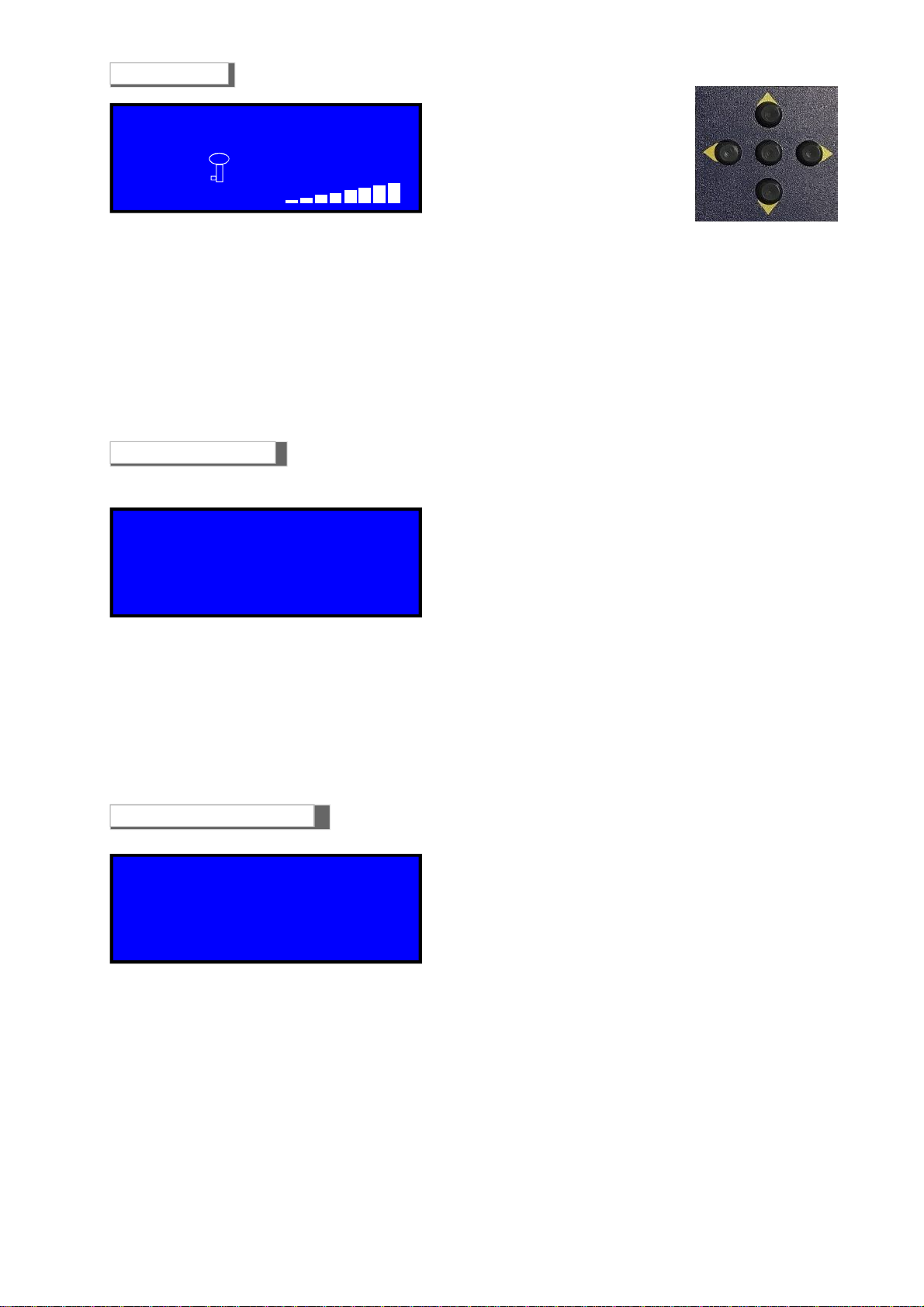
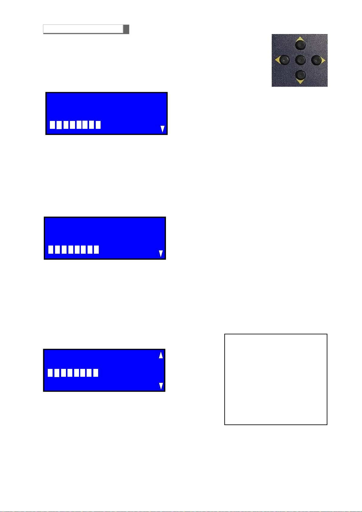
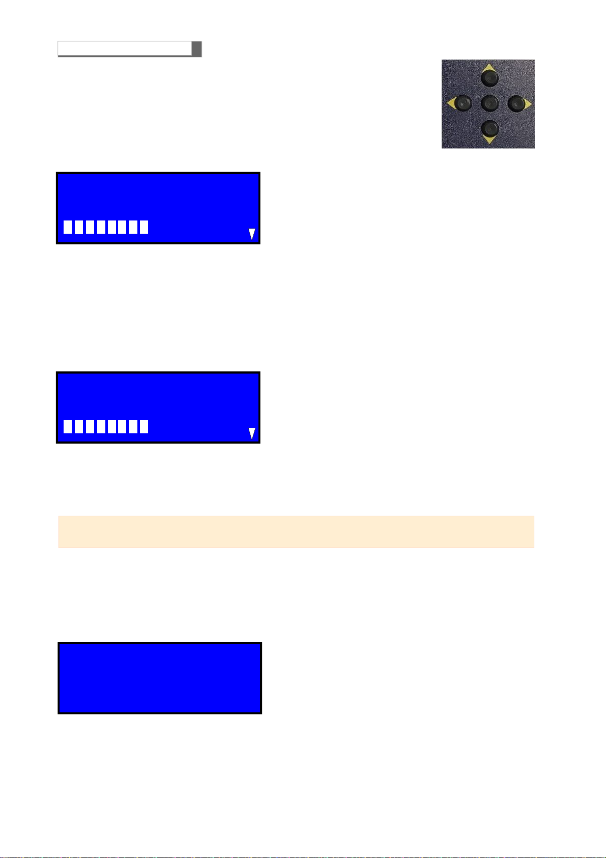
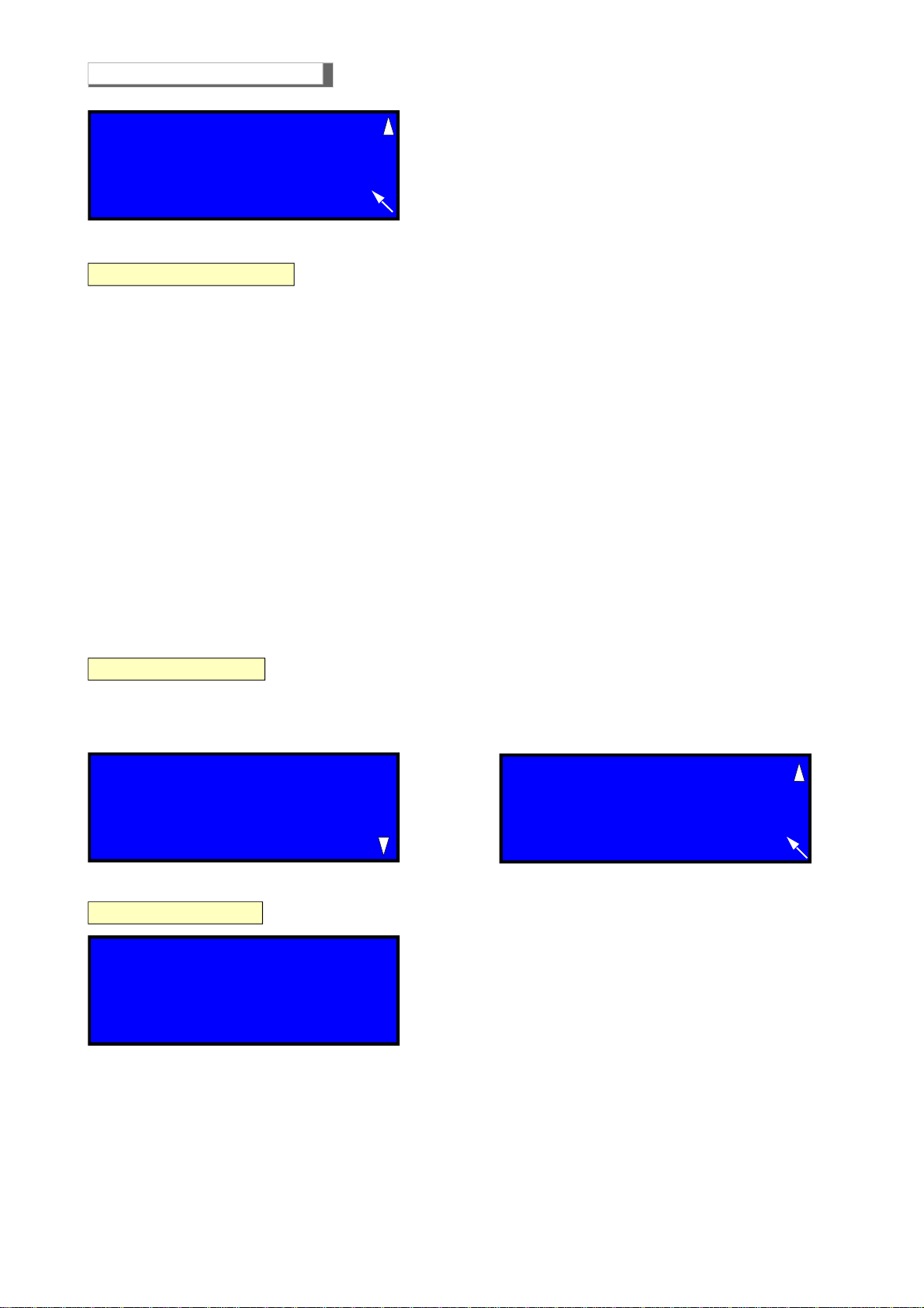
LCD display in normal operating condition
Display: the Brand and the serial number
Display: Date and Time
Display: the probe being monitored
Display: automatic Explosive Gas and Operating range L.E.L. or Toxic Gas ppm
Display: the chart of the amount of gas detected
Display: Warm up on Display appears the “count-down” time
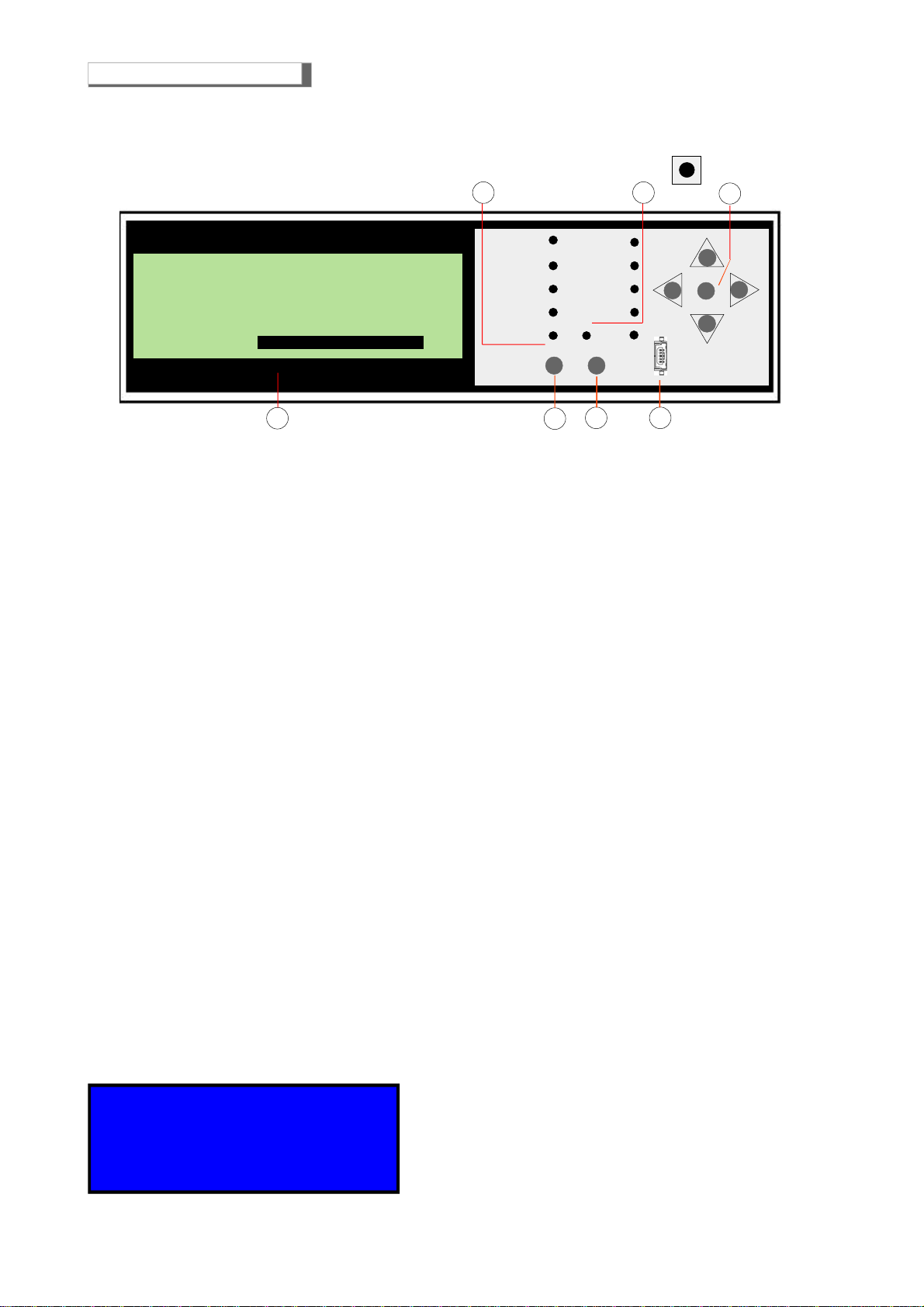
Front Panel
Push-buttons for navigation and confirmation of data set
Test push-buttons for total control of BX308xp that check the performance of both the control unit and the probes
connected to it.
Reset button used to reset alarm and failure memories
LED that displays the silenced external siren. This operation can be performed by entering the Password
All operation and alarm LEDs: read page 4 to find out their functions
LED that displays the charge status of Buffer battery
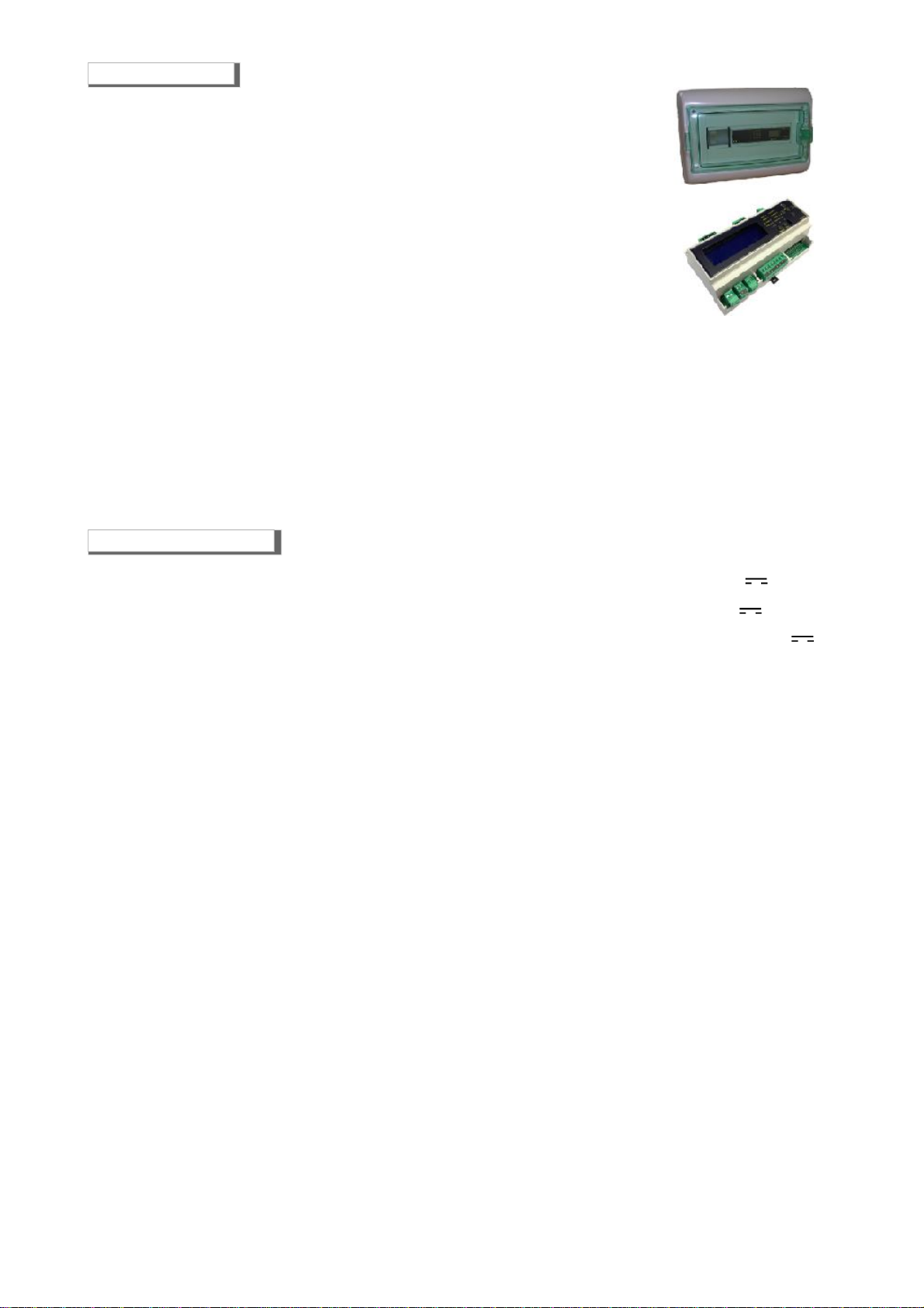
Main Power Supply
unboxed version
.........................................................................12/15 V ± 10%
Main Power Supply
boxed version
................................................................ 110/230VAC 50/60Hz ±10%
Secondary power supply via battery Max 2,2 Ah (not supplied) ....................................... 12,7 V ± 10%
Battery Charger Max 2,2 Ah ...................................................................................................... controlled
Max power demand in alarm with 8 probes connected .................................................. 15W Max @ 12 V
Max power demand in alarm with 8 probes connected ..................................................... 19W Max 240VAC
Relay Contact Range ..................................................................................................... 10A 250V resistive
ALARMS
1st Pre-Alarm ............................ adjustable for every probe from 3% (450ppm) to 16% (240ppm) of L.E.L.
2nd Final alarm for every active area .............................................. set to 20% of LEL or 300 ppm CO
Monitored Gas Indication .................................................................................. Through illuminated display
ALARMS Oxygen .......................................................... <Oxygen deficiency and > Oxygen excess See page7
INDICATIONS
Indicate the percentage of gas detected......................................................................... seen on display
Indication of mains power supplied
, alarms, battery state, probe and battery over load, faults
Manual alarm
indication
........................................................................................................... built-in
Siren ON
indication
................................................................................................................. built-in
Duration of pre-heating phase via count-down ..................................................................... 90 seconds
Manual test .......................................................................................................................... built-in
External siren and internal Buzzer silencing ......................................................... via software operation
ALARM AND PROBES ZONES
Number of Selectable zones ................................................................................................................. 1
Number of connectable Sensors ............................................................................................................. 8
Probes connection/disconnection ............................................................................. via software operation
Connectable probes ............................. Semi-conductor, Catalytic, Electrochemical cell, Pellistore, Infrared Rays
Faults detected by failure circuit ............................................................. Interruption , short circuit or failure
Input signal ..................................................................................................... 4 ÷ 20 mA over 150 Ohm
Operating Range ............................................................................................. 0-20% or 0-100% of L.E.L.
Equipment precision .................................................................................................................... 1% FS
Response time ............................................................................................................................... < 2"
CONNECTIONS
Printer ......................................................................................................... through dedicated USB port
CARD-RLS4 Relay expansion card ............................................................................ each card has 4 relays
CARD-BMS16 .................................................................................................. Converter Current Voltage
GENERALINFORMATION
Operating temperature .................................................................................................... -10°C ÷ + 60°C
Maximum distance between probes and control unit ............................................................................100 m
Cable diameter for connecting probes ............................................................................................. 1 mm2
Connection:
The cable of connection of the probe must not be installed together with the power cables.
Otherwise, make sure to use a shielded cable
Omega bar dimensions DIN EN 50092 9 modules .................................................................. 158x90x58 mm
Degree of Protection ............................................................................................................. in air IP20
Dimensions installed on the “Boxed” ............................................................................... 340*280*160 mm
Degree of Protection on the “Boxed”............................................................................................... IP65
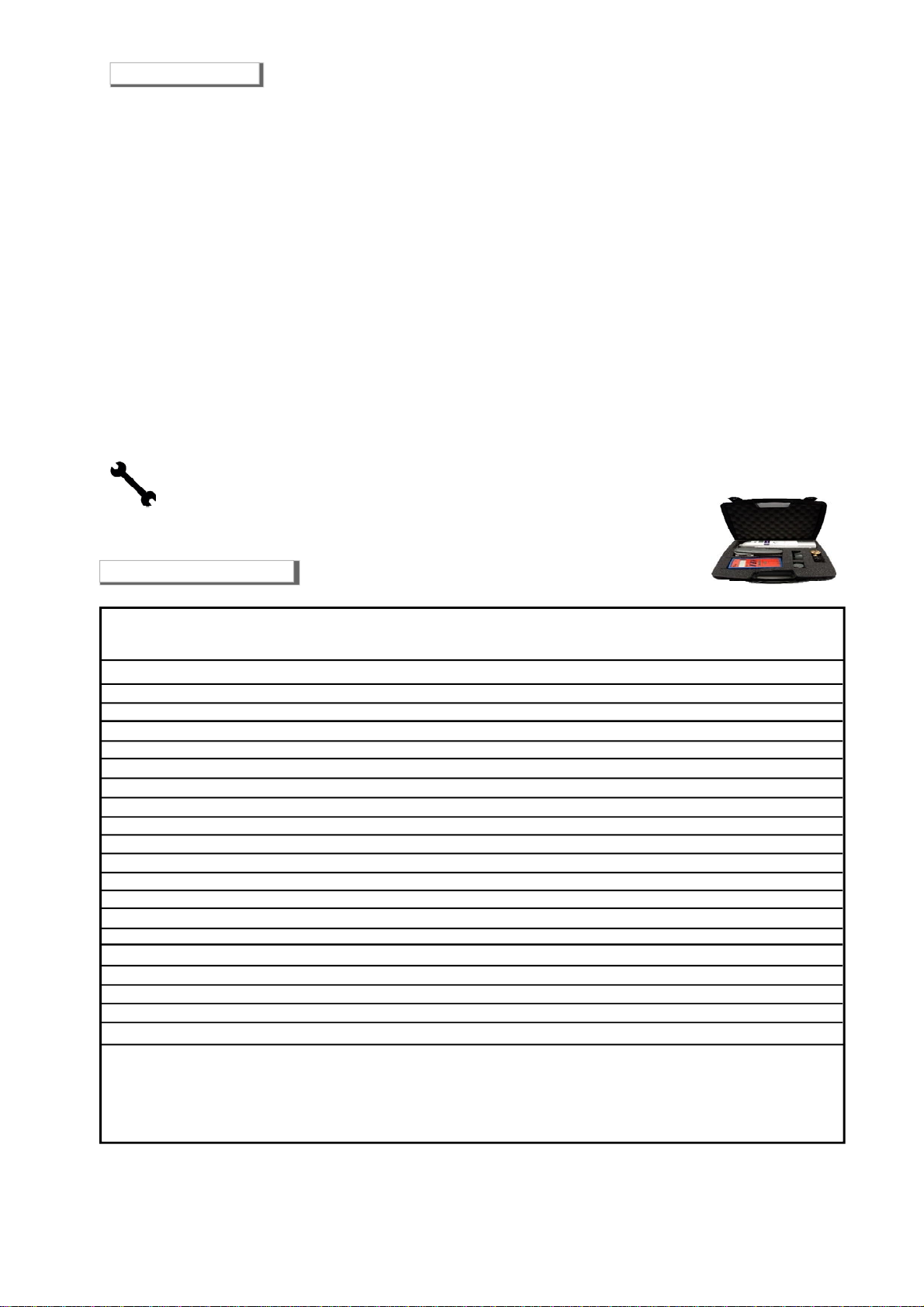
Main specification
Technical specification

Page3
CHECK the integrity of the probe after having removed it from the box.
Check that the data written on the box correspond to the type of gas used.
When doing the electrical connections, follow the drawing closely.
Any use of thedetectorforpurposesotherthanthe intendedone isconsideredimproper,and asa resultof whichBEINAT
S.r.l. therefore disclaims any responsibility for possible damages caused to people, animals or objects.
TERMS and EXPECTATIONS: The installation of the BX308xp, its ordinary and extraordinary maintenance, and its
out of service removal at the end of the functional life guaranteed by the manufacturer, must be carried out by
authorizedand/orspecializedpersonnel.
Do not allow it to become wet.
Do not drop it.
Heavy knocks or falls during transportation or installation can damage the appliance.
Avoid abrupttemperature fluctuations.
Sudden temperature variations can cause condensation and the probe could work poorly.
Cleaning
Never clean the device with chemical products. If necessary, wash with a moist cloth.
Absolutely avoid using any cloth dipped in thinners, alcohol and chemical detergents.
Disposal of the device
Concerning the conservation, the protection and the improvement of the quality of the environment, as well as for the
protection of human health and the careful and rational use of natural resources, the device has to be the object of
aselective collectionfor he disposalof electronic equipments and can not be disposed with the common domestic waste.
The user thus has the obligation to separate the device of the other waste to ensure that it is recycled in a sure way
for preserving the environment For more details on the sites that are involved in the collection, contact the local
administration or the distributor of this product.
Useful Information
Main Compatible Probes
MAINTENANCE
The user periodically (every 6 months) must perform a check of the operation of the control unit by spraying
a suitable test gas at the base of the probes connected until the alarm condition is reached.
• At least once a year make a more accurate check by a specialist technician.
• Disabling the detector must be carried out by qualified personnel.
The installation of the gas detection system does not exonerate. From the observance of all the rules regarding the
characteristics, the installation and the use of the gas appliances. The ventilation of the premises and the discharge of the
combustion products prescribed by the UNI standards as per ART. 3 LAW 1083/71 and the relevant provisions of law.
SG500 Catalytic IP30 Domestic Use CH4-LPG 0÷100% LEL 4÷20 mA ±5 % NO NO
SG544 Catalytic IP44 Tertiary CH4-LPG 0÷100% LEL 4÷20 mA ±5 % NO NO
SGM595 Catalytic IP55 Tertiary See catalogue 0÷100% LEL 4÷20 mA ±5 % Yes NO
SGM595/A Catalytic IP66 Zone 2 See catalogue 0÷100% LEL 4÷20 mA ±5 % Yes NO
SGM533 Catalytic IP55 Tertiary See catalogue 0÷100% LEL 4÷20 mA ±5 % Yes Yes
SG800 Catalytic IP66 Zone 2 See catalogue 0÷100% LEL 4÷20 mA ±5 % Yes Yes
HCF100 SemiCondut IP55 Tertiary FREON 0÷300% ppm 4÷20 mA ±5 % NO Yes
SG895 Pellistor ATEX Zone 1 See catalogue 0÷100% LEL 4÷20 mA ±5 % Yes NO
SG580 Catalytic IP66 Zone 2 See catalogue 0÷100% LEL 4÷20 mA ±5 % Yes NO
SGF100 Catalytic IP64 Zone 2 Methane 0÷100% LEL 4÷20 mA ±5 % Yes Yes
SGF102 Catalytic IP64 Zone 2 LPG 0÷100% LEL 4÷20 mA ±5 % Yes Yes
SGF104 Optical Fluores IP64 Zone 2 Oxygen In % 4÷20 mA ±5 % Yes Yes
SGF106 SemiCondut IP64 Zone 2 FREON 0÷300% ppm 4÷20 mA ±5 % Yes Yes
SGF108 Elettrochimica IP64 Zone 2 H2S 0÷300% ppm 4÷20 mA ±5 % Yes Yes
SGF110 Electrochemical IP64 Zone 2 CO 0÷300% ppm 4÷20 mA ±5 % Yes Yes
SGF112 Catalytic IP64 Zone 2 Hydrogen 0÷100% LEL 4÷20 mA ±5 % Yes Yes
CO100r Electrochemical IP55 Tertiary CO 0÷300% ppm 4÷20 mA ±5 % Yes Yes
CO100Ar Electrochemical IP66 Zone 2 CO 0÷300% ppm 4÷20 mA ±5 % Yes Yes
SG800duct Catalytic IP66 Zone 2 CH4LPG 0÷100% LEL 4÷20 mA ±5 % Yes Yes
CO200duct Electrochemical IP66 Zone 2 CO 0÷300% ppm 4÷20 mA ±5 % Yes Yes
Application in:
Domestic: family accommodation. Local boilers up to 70 kW-h
Tertiary Areas: Large Rooms Boilers, Workshops, Material Deposits, Industrial Kitchens, Large Buildings, Buildings.
Zone 2 - Mixed IP66 ATEX: High probability of escape, high risk locations, premises for which applicable regulations apply.
Zone 1 - Hazardous Area, High Risk Hazards, Rooms for Which Regulations, Tanks, Control Valves are in force.
Probe Sensor Degree Suitable for Gas Range Output Precis. Calibration Relay
Protec. Detected Working Automatic
Sensor

Page 4
BEINAT S/N AD012G
16/010/17 10:10
= = BX308xp ver. 3.0 = =
Count Down 90”
Screen displayed when turning on the BX308/xp.
This screen remains on for 90 seconds.
SN B0205 06/Jan/2013
State 15:48
Probe 05 18% LEL
Enabled
Power
Battery
OL Probes
OLBattery
Fault
PreAlarm
MainAlarm
Exit Alarm
SirenStatus Enter
Test Reset
123
456
Reset Hardware
7
1) Signaling LEDS
a) MAINS LED. It turns on when network voltage is inserted.
b) Battery LED. It turns on when the equipment is powered by battery.
When the LED starts to flash it means that the battery is low.
c) The control unit is equipped with electronic safety devices called OVER LOAD, that are used to prevent
permanent damage of the same. When these LEDs turn on it does not mean that the control unit is not working;
it means that the equipment coupled to it (or the relative connections) are not working.
PROBE OVER LOAD LED: if this LED turns on, it indicates a short circuit or a high absorption of current by the
probes and the relative connection cables. Check the battery and the connection cables.
BATTERY OVER LOAD LED: if this LED turns on it shows that the battery is connected incorrectly or there is
an abnormal current absorption. Check the battery and the connection cables.
d) FAULT LED. This LED turns on and flashes when one of the probes coupled is damaged or the connection
cables are interrupted or there is a connection error. When this LED is turned on, the equipment can no longer
detect the gas and it activates the relays of both threshold levels (the 1st and the 2nd).
To restore operation, the probe must be repaired or removed by pressing RESET using the setting program.
2) Alarm LEDS
a) PRE-ALARM LED(PRE-ALARM). This LED turns on when gas concentration level reaches the pre-alarm
value; the latter can be set from 8 to 16% of L.E.L. and closes the relay contact of 1st THRESHOLD.
b) MAIN ALARM (GENERAL ALARM) LED. This LED turns on when gas concentration reaches a value of 20 %
of L.E.L. and closes the GENERAL ALARM relay contact.
c) MANUAL ALARM LED. This LED turns on when the remote alarm button is pressed.
d) LED for activating the EXTERNAL SIREN. It turns RED when the external siren is disconnected.
Push-Buttons
3) Navigation buttons group. These buttons are used to set the operation of the control unit.
4) RESET button. Press this button to reset all memories.
5) TEST button. By keeping this button steadily pressed you will simulate a gas leak.
6) Printer USB port. Connection for printing the data stored in the memory.
7) Display.
The instrument is equipped with a high performance alphanumeric display with 4 lines for every 20 characters
to facilitate reading all the events. Display background will always be lit up.
Components and comands

Page 5
SN AD012G 16/Ago/16
Single Zone 10:10
Probe 07 Esp. 020% 100%
20,0% LEL
To access the BX308xp setting program you should press the “ENTER” button for 5 seconds.
In normal functioning state, the display shows the following information:
a) Registration number
b) Current date and time
c) Currently detected zone
d) The currently monitored probe, and the type of gas, explosive and/or toxic.
Each connected probe is shown every 8 seconds.
To accelerate the display of the probes press the Left and Right buttons.
To stop the sequence of probes, and analyse the functioning of a specific probe, press “ENTER”.
On the display you will see a key. To unlock it, press again “ENTER”.
e) Display of the percentage of L.E.L. or ppm detected by the probe, and the bar graph of the quantity of gas.
To continue you should enter a password.
The “password” is 1-2-3-4.
Note. The password can be changed by accessing the “Advanced Functions” in the “General Functions” section.
Use the Left and Right buttons to reach the desired number, and press “ENTER”.
Each time you enter a number you will see an a star, until all four a stars appear.
If the password is correct you will see “Password accepted”
If you made a code input mistake, you will see “Wrong password”.
You should re-enter the password. If you do not press any key, you will return to the previous screen.
DATE and TIME SETTING
Use the Left and Right buttons to select “Time Setting”, and press “ENTER”. You will access the current
date and time setting program.
PROBE SETTING
Use the Left and Right buttons to select “Probe Setting”, and press “ENTER”.
You will access the program to select the quantity of zones (1-2-single).
Set the quantity of probes that can be connected, the type the pre-alarm gas percentage and the operative
range of each probe.
GENERAL FUNCTIONS
Use the Left and Right buttons to select “General Functions”, and press “ENTER” to access the program
to select: relay functioning mode, intrinsic safety function activation, activation of the zone alarm lachting
function, activation of the external siren in silent mode, and “Advanced Functions” menu.
By selecting “Advanced Functions” you can access a program to: change the password, read the
datalogger, print the events, and test the probes.
To select Exit to return to the initial program
Initial Screen
Control unit setting
Selection of the setting
Giù
Sù
SX DX
ENTER
Time setting
Probe setting
General Functions
Exit
Input Password
0 1 2 3 4 5 6 7 8 9
* * * *
Password accepted

Page 6
To set the date and time, proceed as follows:
1) Use the RIGHT and LEFT buttons to select day, month, year, hour, minutes.
2) Use the ENTER button to find the desired day, month, year, hour, minutes.
Note. In case of blackout the BX308xp, the set data are not lost.
If the backup clock battery is too low, you will get this error message “Err. bat. Clock” during the warmup phase.
EXITbutton
To exit the program, select “ Return Arrow ”.
Date and Time Setting
Probe Setting
Inserting or Disconnecting Probes, and Selecting the Type Gas, Explosive, Toxic, and Oxygen
Pressing the DOWN button starts blinking the probe 1,each time you press the"ENTER" button, a rectangle will appear
with the text:
Activation/deactivation of probes, and type of gas selection: Explosive or Toxic
Press DOWN to get probe 1 blinking.
Now, each time you press “ENTER” you will get the following box:
E, you have enabled a probe for explosive gas
T, you have enabled a probe for toxic gas
O, you have enabled a probe for oxygen gas
* you have disabled the probe
Use the RIGHT and LEFT buttons to select the desired probe, and repeat the operation outlined above.
This operation should be performed on all probes to be activated.
Use the arrow down to the right and press “ENTER” to access the setting program for the pre-alarm gas percentage.
Giù
Sù
SX DX
ENTER
Date time
16/oct/2017 15:10
1 2 3 4 5 6 7 8
T * T O * * E T T T T T E E E E
Configurazione sonde

Explosive Gas Setting
Page7
Setting pre-alarm percentage
The BX308xp program allows a different pre-alarm threshold per each
connected probe.
Toxic gas Setting
To set other probes, use the RIGHT and LEFT buttons to move to probe 7 (in this case) (“E”). On the first line you
will see the gas percentage of “10% LEL”.
To change the percentage press “ENTER”.
The percentage is increased each time of 1%, starting from 3% of LEL up to a maximum of 16% of L.E.L.
The percentages are increased cyclically.
Use the arrow up to the right and press “ENTER” to return to the previous program.
When this screen appears, the cursor goes on probe 1, (in this case (“T”). On the first
line you will see the gas percentage of “150 ppm”.
To change the percentage press “ENTER”. The percentage is increased each time of 15
ppm, starting from 45 ppm up to a maximum of 240 ppm.
The percentages are increased cyclically.
Probe Setting (continue)
1 2 3 4 5 6 7 8
T * T O * * E T T T T T E E E E
Configurazione sonde
Oxygen Gas Setting
pre alarm
main alarm
Key:
< Oxygen depletion
> Oxygen excess
< 19.9 %
> 21.9 %
< 18.5 %
> 23.5 %
To set Oxygen probes, move with the DX and SX buttons in our case on
probe 4, ("O"). All Oxygen probes have both pre-alarm and alarm fixed
settings.
See the threshold table at the side.
Use the arrow down to the right and press “ENTER” to access the setting program for the “OPERARTIVE RANGE”.
Giù
Sù
SX DX
ENTER
1 2 3 4 5 6 7 8
T * T O * * E E T T T T E E E E
Configurazione sonde
Pre-Al. 10% LEL
1 2 3 4 5 6 7 8
T * T O * * E O

Page 8
Toxic Gas
When this page is displayed, it the cursor is moved to probe
1, “T” in our case
The message “Range Op 0-20% -100% L.E.L.” is not displayed
because the Operating range cannot be modified.
Explosive Gas
Press DOWN and use RIGHT and LEFT buttons to the select the desined probe whict change the Operative
Range. If you are on probe 7 (in this case “E”) on the first line you will see the operative range of “0-
20%L.E.L.”.
To change the value press “ENTER”:every time you press the button the percentage changes from “ Range
Op 0-20%L.E.L.” to “ Range Op 0-100%L.E.L.” and vice versa.
N.B. Please keep in mind that when this operation is peformed, the relative probes must also be setted to the
same range.
Select the top right arrow and press “ENTER” to return to the previous program.
Due to the sheer importance of this operation any change to the operative range shall be confirmed
END: to the exit program, select the “Back Arrow”.
Probe Setting (continue)
Giù
Sù
SX DX
ENTER
Setting the Percentage of Prealarm
The program of the control unit provides that each connected probe may have a pre-alarm
threshold different one from the other. This operation is reserved exclusively for explosive gas.
Range Op
1 2 3 4 5 6 7 8
T * T O * * E T T T T T E E E E
Configurazione sonde
1 2 3 4 5 6 7 8
T * T O * * E E T T T T E E E E
Configurazione sonde
This will change the
operative range !
Are you sure ? Yes No

Page9
Selecting memorisation of Main Alarm
According to the type of installation, you can select the activation or deactivation of the Main Alarm Latching.
By selecting the Latching function, the relay remains closed until the RESET button is pressed.
By unselecting the Latching function, the relay won’t remains closed when the alarm stops.
Note. The memorisation is subdivided in three ways:
1) Memorisation of single zone
2) Memorisation of first zone
3) Memorisation of second zone
Selection
Use the UP and DOWN buttons to select Latching (memorization).
Each time you press “ENTER” the ON/OFF message is changed.
In the “ON” position, the latching function is enabled.
In the “OFF” position, the latching function is disabled.
Once you have selected it, use the UP and DOWN buttons to move to the next selection.
Selecting the functioning mode of the Main Alarm Relay
According to the type of installation, you can select the relay functioning mode.
The relay functioning modes are two: continuous and impulse.
In the “Continuous” position, the relay remains closed until the alarm status continues, or until the alarm
stops.
In the “Impulse” position, the relay remains closed for 20 seconds, and then disenergizes afterwards.
Selection
Use the UP and DOWN buttons to select Relay.
Each time you press “ENTER” the Continuous/Impulse message is changed.
Once you have selected it, use the UP and DOWN buttons to move to the next selection.
Selecting the Positive Safety
According to the type of installation, you can select the Positive Safety function.
Selection
Use the UP and DOWN buttons to select Positive Safety.
Each time you press “ENTER” the ON/OFF message is changed.
In the “ON” position, the Positive safety function is enabled.
In the “OFF” position, the Positive safety function is disabled.
Once you have selected it, use the UP and DOWN buttons to move to the next selection.
General Functions
Giù
Sù
SX DX
ENTER
Relay: Continuous Impulse
Positive Safe: ON OFF
Latch Zone 1: ON OFF
Latch Zone 2: ON OFF

Page 10
Use the UP and DOWN buttons to select: Change Password - Datalogger - Print - Test Probes, and press
“ENTER”.
Now you can change the factory set password (1234), and enter your own.
Use the RIGHT and LEFT buttons to reach the desired number, and press “ENTER”.
Each time you enter a number you will see the selected number, until all four numbers appear.
Once you have entered it, you will get the “CONFIRMED” message.
The program returns to the previous screen after 5 seconds.
Save the password and do not forget it.
From now on you should enter the new password to access the BX308xp programming.
If you forget the password, you can find the “PUK” number in the warranty certificate.
Password Change
Advanced Functions
Siren and Buzzer Silent
Selecting the External Siren Silent Mode
The BX308xp program allows the silent mode for the external siren.
The siren could be annoying during test phases, or extensive alarms.
The silencing is indicated by a red LED on the front panel.
Red LED on, means siren silenced - Red LED off, means siren working
Selection Use the UP and DOWN buttons to select Siren Silent Mode.
Each time you press “ENTER” the ON/OFF message is changed.
In the “ON” position, the siren is enabled.
In the “OFF” position, the siren is disabled.
Selecting the Buzzer Silent Mode
Selection Use the UP and DOWN buttons to select Buzzer Silent Mode.
Each time you press “ENTER” the ON/OFF message is changed.
In the “ON” position, the siren is enabled.
In the “OFF” position, the siren is disabled.
Select Arrow and press “Enter” to return to the Menu.
General Functions (continue)
Siren Active: ON OFF
Buzzer Active: ON OFF
Advanced feat.
New Password
Confirmed
0 1 2 3 4 5 6 7 8 9
3 4 7 9
Password Change
Datalogger
Print
Test probes
Factory Reset

Page 11
To view the other screens, use the UP and DOWN buttons to select the arrows on the right.
Datalogger
Use the UP and DOWN buttons to select Datalogger, and press “ENTER”.
You will get the screen displaying the last 50 detected events.
The displayed events, one per screen, are:
Pre-Alarm, Alarm, Fault, Blackout, Reset, Low Battery, Probe Enabled, Probe
Disabled, Hard Reset.
- Event 06 -
--/---/-- --:--
Retrieving data ...
- Event 05 -
--/---/-- --:--
Retrieving data ...
- Event 02 -
--/---/-- --:--
Retrieving data ...
- Event 04 -
--/---/-- --:--
Retrieving data ...
- Event 03 -
--/---/-- --:--
Retrieving data ...
- Event 01 -
--/---/-- --:--
Retrieving data ...
- Event 06 -
25/Lug/13 08:15
Low Battery
Vbatt= 03.3 V.
- Event 05 -
24/Lug/13 09:15
Reset
- Event 01 -
24/Lug/13 15:28
Probe 16 Pre-Alarm
V=02.6 V I=17,3 mA
- Event 02 -
24/Lug/13 15:28
Probe 12 Alarm
V=02.6 V I=17,3 mA
- Event 03 -
24/Lug/13 08:15
Probe 01 Fault
V=00.o V I=00,2 mA
- Event 04 -
24/Lug/13 08:15
Black-out
General Functions (continue)
Giù
Sù
SX DX
ENTER

Page 12
Print
Use the UP and DOWN buttons to select Print, and press “ENTER”.
Now you can print the following:
The events on the current state of the BX308xp for all probes.
All the events in the datalogger.
Select arrow and press “Enter”
to return to the Menu.
Select arrow and press “Enter” to return to the Menu.
Test Conventional Probes
Use the UP and DOWN buttons to select Test Probes, and press “ENTER”.
Check voltage of probes
This screen is used by technicians to check the voltage detection state compared to the room gas concentration.
The cursor goes on probe 1. The voltage and current detected by the probe are shown.
To read other probes, use the RIGHT and LEFT buttons to reach the desired probe.
General Functions (continue)
Giù
Sù
SX DX
ENTER
Print status
Print datalogger
1 2 3 4 5 6 7 8
T * T T * * E E
1 2 3 4 5 6 7 8
T T T T E E E E
Zone 1 Zone 2
V. 3,2 I=20,2 mA
BEINAT
== BX308/xp ==
Ver: 1.0 S/N Sample
Serial number: 0102
Date Hour
07/oct/17 10:00
State probes
-------------------------
Probe 01 Zone 1
Gas Type: Explosive
Gas Level: 02.9 LEL
Meas.Current: 06.2 mA
Status: Normal
-------------------------
Probe 02 Zone 1
Disabled
------------------------
Probe 03 Zone 1
Disabled
-------------------------
Probe 04 Zone 1
Disabled
-------------------------
Probe 05 Zone 1
Disabled
-------------------------
Probe 06 Zone 1
Disabled
BEINAT
== BX308/xp ==
Ver: 1.0 S/N Sample
Serial number: 0102
Date Hour
07/oct/17 10:00
Datalogger
-----------------------
- Event 01 -
06/jun/2010 08:27
Reset
------------------------
- Event 02 -
07/jun/2010 10:11
Hard Reset
------------------------
- Event 03 -
07/jun/2010 10:27
Vbat=11.8V
----------------------
- Event 04 -
07/jun/2010 11:27
Black-out
------------------------
-Event 05-
06/jun/2010 09:27
Probe 16 Fault
V=00.1 V I=01.1 mA

Page 13
Select “Factory Reset”. Pressing “ENTER” the message starts blinking.
By holding the “ENTER” button for 4 seconds, you will view a frame with 10 empty rectangles that will gradually
fill. At the end, the BX308xp will be totally reset and a new countdown of 90 seconds will begin.
Use the arrow down to the right and press “ENTER” to return to the previous program
Factory Reset
Before proceeding be sure to want to do it, all previously set data will be
reseted.
Expansion cards
CARD-RLS4: 02 (Address card) 03,04.. 16
Relay: 01 02 03 04
Funct.:NOT USED PREALARM ALARM FAULT
Sonda: 01 02, 03, 04 ...16
General Functions (continue)
The control unit can be operate with up to 16 Expansion Relay cards (code: CARD-RLS4).
On each card there are 4 relays which can be associated with the desired probes range.
Each relay may be assigned to one of the following functions: Pre-alarm, Alarm, Fault or Not Used
Each relay may be assigned a range of probes from 1 to 16.
Display
CARD-RLS4- Indicates the hardware address set in the card (read information).
To change the current expansion card press “ENTER”. The expansion card address is pointed cyclically to the
next available.
Relay. Press “ENTER” to choose the relay, from 1 to 4, to be associated to a function.
Function. Press “ENTER” to choose the function of the selected relay between:
NOT USED – PRE-ALARM – ALARM - FAULT
PROBES. Use the “RIGHT” and “LEFT” buttons to select the field “from” or “to”. Press “ENTER” to choose
the probe belonging to the desired range.
To exit the program and save the changes, select “Return Arrow”.
Giù
Sù
SX DX
ENTER
16/10/17
Factory Reset

Page 14
30 cm Light Gases
30 cm Heavy Gases
Middle Height Volatile Gases
PROBE INSTALLATION INFORMATION
Installation and positioning of the probe
The BX308xp control unit belongs to group II and must be installed in a safe area;
Outside the ATEX zone, however, not in boiler rooms or engine room.
The control unit must be accessible and visible to the user.
The BX308xphas an Omega Bar enclosureand is a device suitable for mounting on pre-assembled quads and has IP20
protection. powered at 15 VDC
The BX308xp / boxed complete cabinet is an equipmentsuitable for wall mounting and is powered by 110/240VAC
with IP65 protection
When installing, it is good to use the normal care that an electronic equipment requires:
- Install the equipment away from excessive heat sources.
- Avoid liquids coming into contact with the control unit, remembering that its external structure has IP20 degree of
protection if installed on the Boxed version (cabinet) supplied to the source is IP65.
The probes must be selected with an IP degree depending on the area to be controlled (Kitchens, Boiler
Rooms, Laboratory, etc.) by selecting one of the probes from Beinat from IP30 to ATEX. see page 3
Position of the detection probes
You can connect many types of remote probes to this unit. Therefore, they should be positioned at different heights
depending on the type of gas to be detected.
These heights are:
- 30 cm from the lowest point of the floor in order to detect: Heavy gases (L.P.G. etc.)
- 30 cm from the highest point of the ceiling in order to detect: light gases (Methane, etc.)
- 160 cm from the lowest point of the floor in order to detect: volatile gases (CO, etc.)
It is importanttonote that the remote probes should be installed according to the following restrictions:
1) The probes should not be placed near the appliances to be controlled (boilers, burners, industrial kitchens, etc.)
but on the opposite side.
2) The probes should not be affected by smoke, vapour, and moving air, as they could distort their measurement.
3) The probes should not be placed near sources of heat, ventilators or fans.
It should be noted that the internal GAS sensors of the probe are perishable components with a variable average
life span from 5 to 6 years (you can request the relative table). Therefore, after this period of time has elapsed it
is advisable to replace them.
4) The control of operation and maintenance and / or extraordinary must be carried at least once a year. good
to keep
When turning on leds fault is necessary make the replacement of the probe by a specialized technician.

If the device does not start up.
Check that the power supply is correctly connected. If powered by the battery, check that the is power is correctly
connected.
If the Fault LED lights up.
Check that the connecting cables from the BX308xp to the probes are intact, that the probes are properly powered,
and that the signal cable is correctly connected.
If the Over Load Probe LED lights up.
Check: that the power polarity has not been inverted,that no short-circuit ispresent,that the probes were not damaged
during installation, that no excessive current absorption is present.
If the Over Load Battery LED lights up.
Check that the connection cables are not short-circuited, that the polarity has not been inverted, or that the battery
is not damaged.
If the control unit is repeatedly issuingan alarm.
Check that there are no gas leaks.
If the alarm signal and the FAULT indicator light turn on together, check the probes.
If the control unit is issuing an alarm and does not shut off the devices connected to it.
Check that the wiring is correct and that the jumper that carries power to the relay has been set properly. All relays
must be free from electrical power. Check the drawing of the connections.
If a 12Vdc solenoid valve , is connected to the BX308/xp, which does not work well
Direct connection of 12Vdc solenoid valves or sirens to the BX308xp is not permitted.
An external power unit must always be used.
The BX308xp gives a max current of 200mA.
If other problems arise, a specialised and/or authorised technician and/or the Distributor of BEINAT S.r.l.
should be contacted directly.
1) Apply power using the proper external switch. This switch should be fitted with protection fuses.
2) You will notice that some LEDs will light up in turn for about 20 seconds.
3) The display will start the COUNT DOWN of about 90 seconds (warm up). At the end the control unit is ready
for detection.
4) Pressing and holding down the TEST button, you can obtain a gas leakage simulation.
The control unit will carry out the following:
- It will light up the 13% LEL or the 200ppm (with reference to CO) LED, and the PRE-ALARM LED, switching
the 1st threshold relay. The buzzer will issue a low frequency sound.
- Later, it will light up the 20% LEL or the 300ppm (with reference to CO) LED, the MAIN ALARM LED. In addition
to maintaining the PRE-ALARM relay switched, it will also switch the MAIN ALARM relay. The MAIN ALARM LED
will start blinking and the buzzer will issue a higher frequency sound.
When releasing the TEST button, you will see the opposite: Only the blinking MAIN ALARM and the 20% L.E.L.
LEDs will remain ON.
When the latching is enabled, the main alarm will continue until the RESET button is pressed, clearing the alarm
from the memory.
5) To complete the test, carefully read the probe instruction manual and perform the sensor test by issuing
gas from a pre-calibrated gas bottle.
6) If you want to simulate a zone FAULT, you only need to disconnect the return cable of one or all the probes.
The control unit will carry out the following:
- The FAULT and MAIN ALARM LEDs will light up and blink;
- The buzzer will issue a continuous sound;
- The FAULT and MAIN ALARM relays will switch.
Reconnect the return cable and press RESET to restore the control unit functioning.
Beforecallingatechnician,check...
Turn-on
Page 15
0
1
3
2
1,1
V.
Voltmeter
WARNING.
This measurement should
be performed in clean air.
0,6
1 2 3 4 5 6 7 8
3 2 1
Probe 1 3 2 1
Probe 2 3 2 1
Probe 3 3 2 1
Probe 4 3 2 1
Probe 5 3 2 1
Probe 6 3 2 1
Probe 7 3 2 1
Probe 8
15VDC+

Page 16
WARNING.
Before connecting to the mains power, ensure the voltage is correct.
Carefully follow the instructions and the connections according to Regulations inforce, keeping in mind that
the signal cables should be laid separate from the power cables.
An automatic cut-off switch (appropriately identified as devicesectioning of the detector) should be
incorporated in the electrical system, adequatelylocated and easily accessible.
Electrical Connections
Main power 110/240 VAC
1 2 3
Ph N
Connection port forconnecting a
new card
Connection plug to the
control unit
RL1
RL2
RL4
RL3
Green led, voltage switched
Yellowled, transmission
Tens Unit
Example to select an address
Turn the Switch of tenths until you find the
desired tenth. For example: 0
Turn the Switch of units until you find the
desired unit. For example: 6
In this way you will set the address “ 6
Eachconnectedboardmusthaveanaddress
unique to avoid conflicts in the data
transmission.
Toentertheaddresses ofeachCARD-RLS4you
have to act through the rotary switches that
each CARD possesses, with them you can
select the desired address from 1 to 16
3 2 1
C
NO
NC
230 VAC
N
Ph
3 2 1
C
NO
NC
N
Ph
230 VAC
EV NC 230 VAC EV NA 230 VAC
Each relay can be coupled to the selected probe and now
you can match all the functions you want
Note!
All relays are voltage free.
Capacity Contacts 10A 230VDC resistive

Page 17
ElectricalConnections
Warning!! All relays are voltage free. Contact capacity 10 A resistives
SN B0205 06/Jan/2015
State 15:48
Probe 05 18% LEL
Enabled
Power
Battery
OL Probes
OLBattery
Fault
PreAlarm
MainAlarm
Exit Alarm
SirenStatus
Test Reset
CNC
NO
CNC
NO
Prealarm
Main Alarm
1 2 3 4 5
CNC
NO
CNC
NO
Fault Sirena Ext
6 7 8 9
Manual alarm PAM-NC
1 2 3 4 5 6 7 8
3 2 1
Sonda 1 3 2 1
Sonda 2 3 2 1
Sonda 3 3 2 1
Sonda 4 3 2 1
Sonda 5 3 2 1
Sonda 6 3 2 1
Sonda 7 3 2 1
Sonda 8
15VDC+
Characteristics standard switching power supply 230 VAC 15
N.B. Power supply included in the box version
+
+
Cards
Relay Conversion
12 V

Page 18
NC NC
Connecting solenoid valve Normally Closed with Positive Safety
Connecting aSolenoid valvewith sirens to12VDC, throughapower switcing.The powersupply should
be adequate to the consumption of the components
Electrical connections
Connecting a solenoid valveNormally Closed without Positive Safety
CNC
NO
CNC
NO
CNC
NO
CNC
NO
1 2 3 4 5 6 7 8 9
NA NC
Power supply Switching
Ph
N
12 VDc
+
Power supply
110/240 VAC
Solenoid valves Prealarm Fault Siren ext
Ph
N
230 VAC
C
NO
C
NO
CNC
NO
CNC
NO
1 2 3 4 5 6 7 8 9
Solenoid valve Prealarm Fault Siren ext
NC
Ph
N
CNC
NO
CNC
NO
CNC
NO
CNC
NO
1 2 3 4 5 6 7 8 9
Solenoid valves Prealarm Fault Siren ext
NA NC
230 VAC

Page 19
90 mm
45 mm
37 mm
90 mm
45 mm
159 mm
Measurements anddimensions of the controlunit in box IP65
Dimension ofthe9modulesOmega-typesize DIN EN50092
340
280
280
160
WARNING! Actions to be taken in case of alarm
Gas
1) Put out all free flames.
2) Close the main gas tap or the LPG cylinder tap.
3) Do not turn any lights on or off; do not turn on any electrical device or appliance.
4) Open windows and doors in order to increase ventilation.
If the alarm stops, its cause must be found and the relevant consequent measures taken.
If the alarm continues and the cause of gas presence cannot be found or removed, abandon the building and call
the emergency services when outside (fire department, distributors, etc.)
IMPORTANT: The operation test should not be carried out with the gas tap as this does not guarantee a
sufficient concentration to activate the general alarm.
Warning !!
If you have the following symptoms: vomiting, sleepiness, or else, go to the closest first aid station
and inform the operators that you could have been poisoned by Carbon Monoxide, or by an excess
or deficiency of oxygen
340
280
BEINAT S/N AD012G
21/10/15 10:10
= = BX308 ver. 1.0 = =
Count Down 90”
BX308/xp

Registration number
Stamp and signature of the dealer
Lo styling è della b & b design
In agreement with its continuous development policy, we reserve the right to modify its products without notice.
Purchase date
Control Unit BX308/xp
Madein Italy
IP65
BEINAT S.r.l. Via Fatebenefratelli 122/C
10077, S. Maurizio C/se (TO) - ITALY
Tel. 011.921.04.84 - Fax 011.921.14.77
http:// www.beinat.com
Help Desk - laboratorio@beinat.com
INSURANCE. This device is insured by the SOCIETÀ REALE MUTUA for the PRODUCT'S GENERAL LIABILITY up to a maximum
of 1,500,000.00 EURO against damages caused by the device in case of failures in functioning.
WARRANTY. The warranty term is 3 years from manufacturing date, in agreement with the following conditions. The
components acknowledged as faulty will be replaced free of charge, excluding the replacement of plastic or aluminium cases,
bags, packing, batteries and technical reports.
The device must arrive free of shipment charges to BEINAT S.r.l.
Defects caused by unauthorized personnel tampering, incorrect installation and negligence resulting from phenomena
outside normal functioning shall be excluded from the warranty.
BEINAT S.r.l. is not liable for possible damage, direct or indirect, to people, animals, or things; from product faults and from
its enforced suspension of use.
DISPOSAL OF OLD ELECTRICAL & ELECTRONIC EQUIPMENT.
This symbol on the product or its packaging to indicates that this product shall not be treated as household waste. Instead, it shall be handed
over to the applicable collection point for the recycling of electrical and electronic equipment, such as for example:
- sales points, in case you buy a new and similar product
- local collection points (waste collection center, local recycling center, etc...).
By ensuring this product is disposed of correctly, you will help prevent potential negative consequence for the environment and human health,
which could otherwise be caused by inappropriate waste handing of this product. The recycling of materials will help to conserve natural
resources. For more detailed information about recycling of this product, please contact your local city office, your household waste disposal
service or the shop where you purchased the product.
Attention: in some countries of the European Union, the product is not included in the field of application of the National Law that applies
the European Directive 2002/96/EC and therefore these countries have no obligation to carry out a separate collection at the “end of life”
of the product.
BE-V.3 43 17
Table of contents
Other BEINAT Control Unit manuals