Address
Each text disp ay must be a ocated a unique
address within the fo owing ranges:
Modbus protoco 1 – 247
BEKA protoco 0 – 247 Zero reserved for
Legacy protoco 0 –15 sing e unit app ications.
Op Mode
Five different eve s of communications security
to be se ected, ranging from immediate
execution of a command with no
acknow edgement, to a requirement for a 16 bit
cyc ic redundancy check. See the Serial Text
Display - Programming Guide for a detai ed
exp anation.
Not avai ab e with Legacy protoco .
Key mode
Key press data can be returned in three ways.
See Response Format Section in the Serial
Text Display - Programming Guide. Not
app icab e with Legacy protoco .
Keypad
This function a ows the instrument front pane
push-buttons or externa push-buttons to be
used for operator inputs. Whichever are
se ected, the instrument front pane push-
buttons are used for configuration.
This function is not avai ab e when Legacy
protoco is se ected.
Settings
A ows the back ight brightness and contrast of
the BA484D disp ay to be adjusted.
Screens
One of nine standard screens or a custom
screen may be se ected.
Not app icab e with Legacy protoco .
Quick access
This function enab es the quick access menu
described in section 7.4. When ‘On’ is se ected
an operator can adjust the screen bri iance and
contrast without having access to other
conditioning parameters.
Access code for the Quick Access Menu
‘Access Code’ in the disp ay menu defines the
four digit a phanumeric code that must be
entered to gain access to the instrument’s quick
access menu. A pha characters are case
sensitive. Defau t code 0000 a ows direct
access without a code.
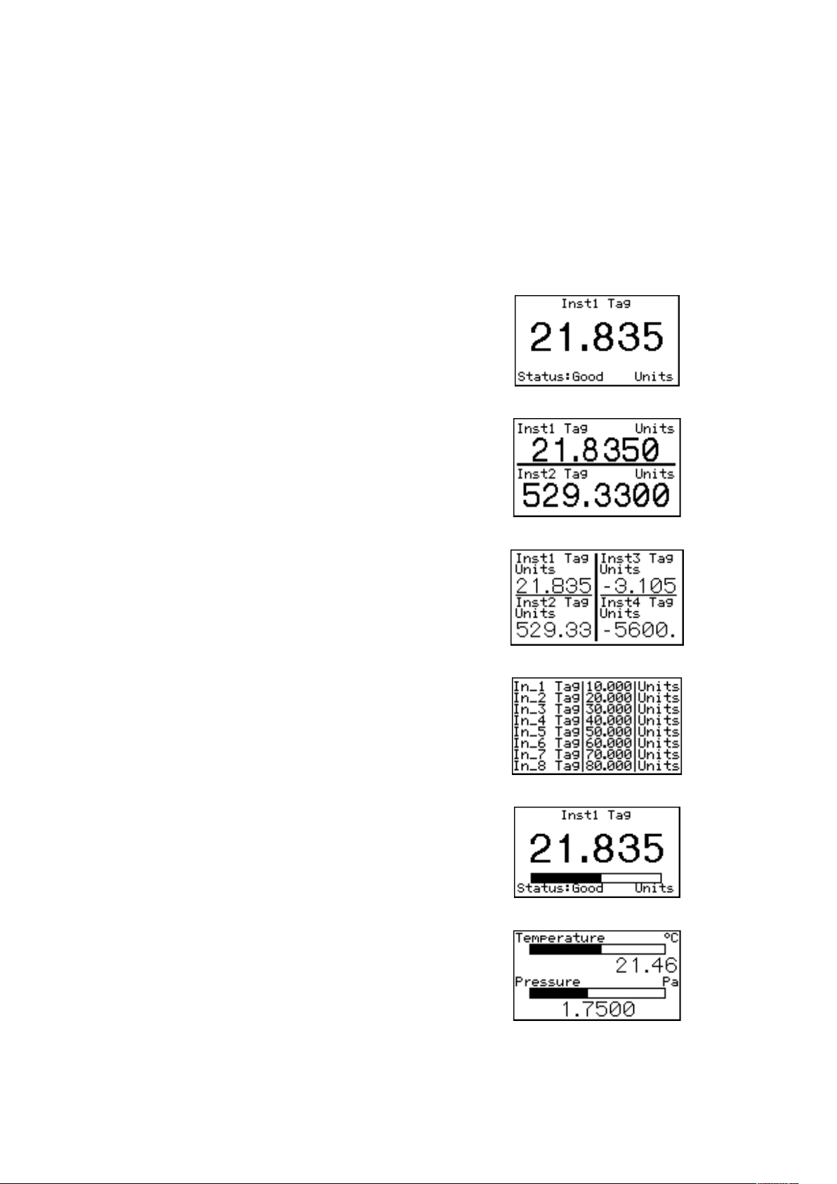
Status Text
The two sing e variab e screens inc ude a
message ‘Status: Good or Status: Bad’, the
Status Text function a ows this message to be
inhibited.
Variable Color
The background co or of variab es depends on
the IN_X Status Coi s. ‘Status: Good or Status:
Bad’ set a norma or inverted co or on the
variab e’s background. 'For furt er information
regarding status please refer to t e "Data
Status" paragrap on page 8 of "Modbus
Interface Guide" or page 16 of t e
"Programming guide”
Last Valid Input
This function a ows the number of process
variab es to be entered so that when scro ing
the disp ay unused screens are not shown.
Access code for the Configuration Menu
‘Code’ in the main menu defines the four digit
a phanumeric code that must be entered to gain
access to the instrument configuration menus.
A pha characters are case sensitive. Defau t
code 0000 a ows direct access without a code.
Unit information
Disp ays the instrument mode number and the
firmware version.
Configuration defaults
‘Defau t’ a ows the configuration defau t defined
in section 6.1 to be g oba y set.
6.4 Quick Access Menu
The quick access menu a ows an operator to
adjust the back ight bri iance and the disp ay
contrast without having access to the other
configuration parameters.
The quick access menu is accessed by operating
the P and Up push-buttons simu taneous y. If the
quick access menu is not protected by an access
code the bri iance and contrast contro s wi be
disp ayed immediate y. If an access code other
than the defau t code 0000 has a ready been
entered, the BA684D wi request that the access
code be entered. Section 6.2 exp ains how an
access code shou d be entered.
The back ight bri iance is adjusted using the Up
and Down push-buttons. Operating the P push-
button wi transfer contro to the disp ay contrast
adjustment. When both are set as required
operating the E button wi store both settings and
return the instrument to the operating mode.