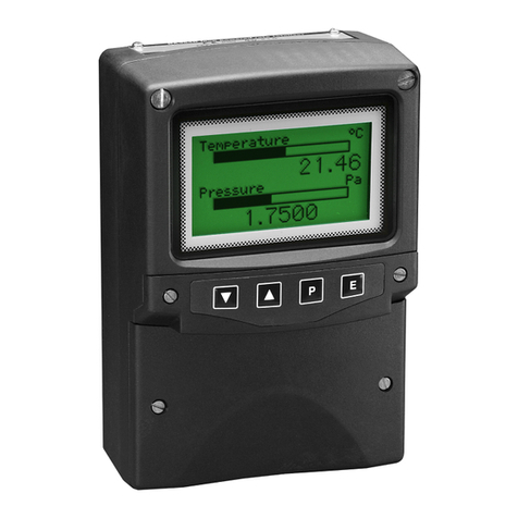
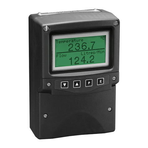
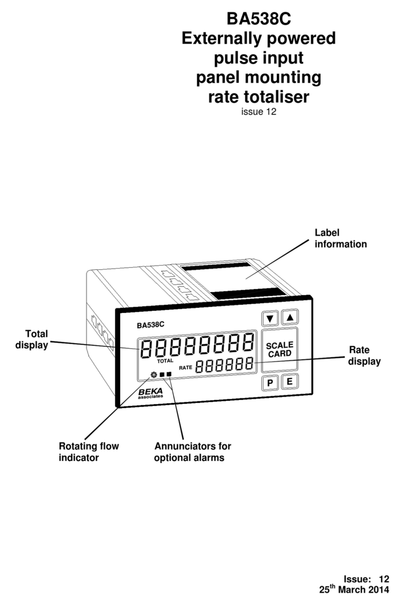
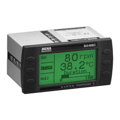
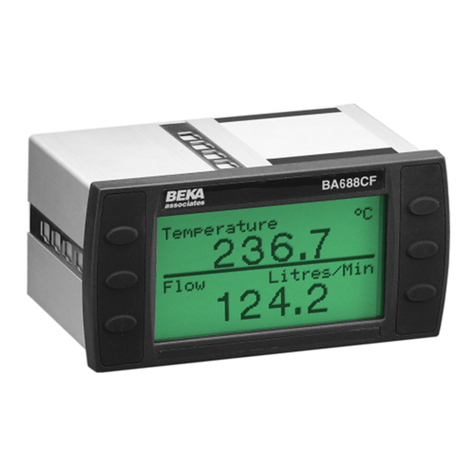
BEKA BA488C Operating instructions

Issue 6
5October 2009
Serial text display
Programming Guide
[Version 3.4 Firmware ]

This guide applies to the following models:
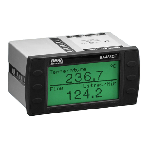
BA488C - Panel mounted, Intrinsically Safe
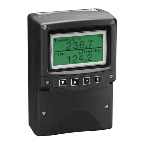
BA484D - Field mounted, Intrinsically Safe
BA688C - Panel mounted, Safe Area
BA684D - Field mounted, Safe Area

Contents
Introduction ...................................................................................................................................................................... 1
What’s in this Programming Guide............................................................................................................................. 1
What’s in the Instruction Manuals.............................................................................................................................. 1
What’s in the Modbus Interface Guide ....................................................................................................................... 1
Other sources of information....................................................................................................................................... 1
Enhanced Features ...................................................................................................................................................... 2
Instrument Features ......................................................................................................................................................... 3
Display .......................................................................................................................................................................... 3
Switch Inputs................................................................................................................................................................ 3
Switch Outputs ............................................................................................................................................................. 3
Afew words about Modes… ............................................................................................................................................ 4
Display Features ............................................................................................................................................................... 5
Write Modes.................................................................................................................................................................. 5
Background Modes ...................................................................................................................................................... 6
Frames ............................................................................................................................................................................... 7
Active and Visible Frames ........................................................................................................................................... 7
Saved Frame Locations................................................................................................................................................ 8
The BEKA Protocol.......................................................................................................................................................... 9
Command format ....................................................................................................................................................... 10
Response format......................................................................................................................................................... 10
Key Mode 0 (Default) ........................................................................................................................................ 10
Key Mode 1........................................................................................................................................................ 10
Key Mode 2........................................................................................................................................................ 11
Operational Modes ..................................................................................................................................................... 11
CRC Generation ......................................................................................................................................................... 11
Multidrop Operation: ................................................................................................................................................. 12
Graphics Transfers......................................................................................................................................................... 13
File Format ................................................................................................................................................................ 13
Downloads .................................................................................................................................................................. 13
Uploads ....................................................................................................................................................................... 14
Standard Screens ............................................................................................................................................................ 15
Cyclic Data ...................................................................................................................................................................... 16
Basic Concepts ........................................................................................................................................................... 16
Updating using ASCII values .................................................................................................................................... 17
Updating using Binary Data...................................................................................................................................... 17
Data Timeout.............................................................................................................................................................. 17
Mapped Variables........................................................................................................................................................... 18
Scripting & Pattern Matching....................................................................................................................................... 18
Command Summary ...................................................................................................................................................... 19
Screen Handling & Text ............................................................................................................................................ 19
Attributes .................................................................................................................................................................... 20
Pixel Graphics ............................................................................................................................................................ 20
Line Graphics ............................................................................................................................................................. 21
Mapped Variables....................................................................................................................................................... 21
System ......................................................................................................................................................................... 22
Scripting ..................................................................................................................................................................... 23
Command Reference ...................................................................................................................................................... 24
<..> Command ............................................................................................................................. 25
<AFn> Active Frame........................................................................................................................ 26
<BDy,x,l> Box Draw ............................................................................................................................. 27
<BMn> Background Mode................................................................................................................ 28
<CA> Centre Align ......................................................................................................................... 29
<CCn> Check Code .......................................................................................................................... 30
<CD> Cyclic Data .......................................................................................................................... 31

<CE> Configuration Enable........................................................................................................... 32
<CI> Command Implement ........................................................................................................... 33
<CLn> Clear Line ............................................................................................................................ 34
<CMy,x> Cursor Move ........................................................................................................................ 35
<CP> Configuration Prohibit......................................................................................................... 36
<CRn,m> Cyclic Redundancy Check.................................................................................................... 37
<CS> Clear Screen......................................................................................................................... 38
<CTn> Cyclic Data Timeout ............................................................................................................ 39
<CVn,string> Cyclic Variable .................................................................................................................... 40
<CW> Clear Window ...................................................................................................................... 41
<DBn,m,p,q,r> Define Bargraph .................................................................................................................. 42
<DDn,m> Define Decimal .................................................................................................................... 43
<DFn> Download Font .................................................................................................................... 44
<DG> Download Graphic............................................................................................................... 45
<DLn,m,p> Define Limit ......................................................................................................................... 46
<DS> Download Screen ................................................................................................................. 47
<DTn,string> Define Tag............................................................................................................................ 48
<DUn,string> Define Units ......................................................................................................................... 49
<DVn,m,p,q,r> Define Variable.................................................................................................................... 50
<DWyt,yb,xl,xr> Define Window..................................................................................................................... 51
<EBn> Erase Bargraph.................................................................................................................... 52
<EF> Enable Flashing ................................................................................................................... 53
<EL> Erase Line ............................................................................................................................ 54
<EVn> Erase Variable ..................................................................................................................... 55
<F1> Font 1................................................................................................................................... 56
<F2> Font 2................................................................................................................................... 57
<F3> Font 3................................................................................................................................... 58
<F4> Font 4................................................................................................................................... 59
<F5> Font 5................................................................................................................................... 60
<FL> Flashing ............................................................................................................................... 61
<FR> Font Restore......................................................................................................................... 62
<FS> Fill Screen............................................................................................................................ 63
<FW> Fill Window.......................................................................................................................... 64
<GBn> Graphic Block ...................................................................................................................... 65
<HBn,m> Horizontal Bargraph............................................................................................................ 66
<HC> Home Cursor........................................................................................................................ 67
<HRn,m,p> Horizontal Rotate................................................................................................................. 68
<HSn,m,p,q,r,s,t> Horizontal Scroll .................................................................................................................. 69
<IF> Inhibit Flashing.................................................................................................................... 70
<KF> Keep Fonts ........................................................................................................................... 71
<LA> Left Align.............................................................................................................................. 72
<LF> Line Feed ............................................................................................................................. 73
<LHx,l> Line Horizontal .................................................................................................................... 74
<LN> Line New .............................................................................................................................. 75
<LVy,l> Line Vertical......................................................................................................................... 76
<MCn> Make Connection ................................................................................................................. 77
<NA> No Align ............................................................................................................................... 78
<NL> No Linefeed .......................................................................................................................... 79
<NS> New Screen........................................................................................................................... 80
<NU> No Underline........................................................................................................................ 81
<ODn> Output De-energised............................................................................................................ 82
<OEn> Output Energised ................................................................................................................. 83
<PM> Pixel Mode ........................................................................................................................... 84
<RA> Right Align ........................................................................................................................... 85
<RB> Reboot .................................................................................................................................. 86
<RC> Release Connection.............................................................................................................. 87
<RFn> Restore Frame...................................................................................................................... 88
<RLn> Restore Logo ........................................................................................................................ 89
<RM> Row Mode ............................................................................................................................ 90
<RS> Request Status ...................................................................................................................... 91
<SAn> Speed Adjust......................................................................................................................... 92
<SBn> Set Backlight ........................................................................................................................ 93
<SD> Screen Defaults .................................................................................................................... 94
<SFn,m> Save Frame .......................................................................................................................... 95
<SHn> Status Hide ........................................................................................................................... 97
<SL> Save Logo............................................................................................................................. 98
<SOn> Screen Option....................................................................................................................... 99
<SSn> Screens to Scroll ................................................................................................................ 100
<ST> Steady................................................................................................................................. 101
<SVn> Show Variable.................................................................................................................... 102
<SW> Smart Wrap ........................................................................................................................ 103
<TOn> TimeOut ............................................................................................................................. 104
<TW> Text Wrap........................................................................................................................... 105
<UE> Upload Enable ................................................................................................................... 106
<UL> UnderLine .......................................................................................................................... 107
<US> Upload Screen.................................................................................................................... 108
<VBn,m> Vertical Bargraph .............................................................................................................. 109
<VFn> Visible Frame..................................................................................................................... 110
<VLn> Variable Last...................................................................................................................... 111
<WMn> Write Mode......................................................................................................................... 112
<WSn> Write Soft character ........................................................................................................... 113
<WTstring> Write Text........................................................................................................................... 114
Advanced Commands................................................................................................................................................... 115
Scripting Control Commands .................................................................................................................................. 115
Script Commands ..................................................................................................................................................... 115
Pattern Matching Commands .................................................................................................................................. 116
Scripting ........................................................................................................................................................................ 117
Overview ................................................................................................................................................................... 117
Downloading and controlling scripts....................................................................................................................... 117
Operation with BEKA protocol................................................................................................................................ 117
Operation with Modbus RTU Protocol.................................................................................................................... 118
Script Flow ............................................................................................................................................................... 118
Key Handling............................................................................................................................................................ 119
Jump Register........................................................................................................................................................... 120
Delays and Waits ...................................................................................................................................................... 120
Events ....................................................................................................................................................................... 121
Script Event Update (Firmware 3.4 Onwards)........................................................................................................ 121
Timer Event (Firmware 3.4 Onwards) .................................................................................................................... 123
Script Errors ............................................................................................................................................................. 124
Script Timeout (Firmware 3.4 Onwards) ................................................................................................................ 124
Script Strings (Firmware 3.4 Onwards) .................................................................................................................. 124
Scripting Control Commands .................................................................................................................................. 126
Script Commands ..................................................................................................................................................... 127
Pattern Matching .......................................................................................................................................................... 129
Overview ................................................................................................................................................................... 129
Pattern Capture ........................................................................................................................................................ 129
Pattern Processing ................................................................................................................................................... 131
Responding to the host ............................................................................................................................................. 135
Packet Matching Commands ................................................................................................................................... 136

1
Introduction
This guide describes the BEKA Mode Protocol for the BA488C, BA484D, BA688C and BA684D Serial Text Displays.
This information is only required when programming a host to communicate with these displays; it is not required by
the end user. The target audience for this guide are software programmers with some experience in communicating with
ASCII devices. As the Modbus protocol is now natively supported (RTU slave only), connection to standard PLCs and
industrial computers is greatly simplified.
•For hardware installation information, please refer to the separate instruction manuals available for each
model.
•For an overview of how to use these displays on a Modbus system, please refer to the “Serial Text Display -
Modbus Interface Guide”.
The BEKA protocol is very straightforward, being loosely based on the principals of HTML. Simple text messages can
be displayed by using only a handful of commands. However, with a bit more perseverance, some quite advanced
displays can be created.
What’s in this Programming Guide
•Adescription of the instrument display
•An overview of the protocol
•Specific information on more advanced features
•Acommand summary, where the commands are grouped together by function and presented in a series of
tables
•Acommand reference, where each command is listed in alphabetical order and covered in detail. The
information is presented in a consistent layout and examples given to demonstrate the use of the command in
context.
What’s in the Instruction Manuals
•An overview of the instrument
•Intrinsic Safety Certification information
•System Design and Installation
•Configuration
•Programming Overview
•Maintenance
What’s in the Modbus Interface Guide
•An overview of the instrument
•Adescription of the memory map for the Modbus protocol
•Adescription of the various data types that are used
•Instructions on how to use the instrument in its standard non-programmed modes
Other sources of information
Our website at www.beka.co.uk has several files available to download:
•All of the examples in this guide
•Demonstration programs showing the capabilities of the display
•A‘Virtual Instrument’ – a PC based simulator that behaves exactly like the real thing. This can be used during
program development or to demonstrate the application to end users

2
Enhanced Features
This product is an enhanced version of our original Serial Text display (BA488C / BA484D) . It is compatible with all
existing applications as none of the existing commands have been altered.
The following features have been added as standard in the Version 3 firmware, released in July 2005:
Modbus Protocol
(RTU Slave Only)
This allows a display to easily be attached to most process control systems and
PLCs as a Modbus Slave. Registers are provided to control the display without
using the BEKA protocol commands and show the process variables on a
series of standard screens. However, more complex applications can be
implemented by using BEKA commands over the Modbus protocol.
Please see the “Serial Text Display – Modbus Interface Guide” for details.
Cyclic Data & Mapped Variables For ASCII serial devices without Modbus, a set of commands has been added
to allow the standard screens to be easily used. The addition of Mapped
Variables within the product makes it much easier to update displayed values
automatically, without the need for screen redraws.
Standard Screens A set of standard screens is included to display up to 8 parameters - no
programming is necessary.
Scripting The display can run through a set of commands independently of the host it is
attached to. This allows an application to be loaded into the display only once,
leaving the host free to perform other tasks.
Pattern Matching A fixed format data string from a dumb instrument can be decoded by the
display and the results shown on screen. This feature allows a local display to
be incorporated anywhere on the installation without using host resources.
Speed Increase A command has been added (SA) to increase the internal speed of the
Intrinsically Safe versions of the display at the expense of a reduction in
backlight intensity. Screen redraws are much faster, and more complex pattern
matching can be achieved.
Soft fonts storage There is now the ability to save Font 5 soft fonts.
The following features have been added as standard in the Version 3.4 firmware, released in September 2009:
Integer Variables Modbus variables can now be input as 16 or 32 bit integers in addition to
floating point format. This makes the display easier to interface to simpler
devices.
Script String Variables String variables have been added to make it easier to display operator
information.
Standard Screens Two more standard screens have been added to display 8 parameters - no
programming is necessary.
The following existing commands are now permitted in standard screen mode:
<CE>, <CP>, <OEn>, <ODn>, <SBn>.
Hide Unused Variables In applications where fewer than 8 variables are required, it is now possible to
hide unused values making it more intuitive for the operator.
Status visibility The ability to show or hide the data status has been added. This is useful when
the context of that information has the potential to confuse the operator.
Scripting Several more scripting commands have been added.
The safe area versions of the product are not limited by Intrinsically Safe power limitations, and will execute commands
approximately four times faster. They are also able to communicate with the host at speeds up to 115KBaud via RS485,
or up to 19.2KBaud via RS232
After reading through this guide, if you still have a problem getting the results you need then email us at

3
Instrument Features
Adetailed overview of the instrument is given in the instruction manual for each product. This should be read before
implementing any system using this instrument. However it is useful to summarise the main features of the display
before attempting to design any controlling software application.
Display
The instrument display is organised as 120 pixels horizontally by 64 pixels vertically. Each pixel is approximately
0.7mm square which makes it ideal for displaying text and simple graphics. The size of the pixels improves the contrast
and hence the readability at greater distances.
The display is also backlit by an ultra-efficient green LED module which enables the screen to be viewed in all
conditions, from bright sunlight to total darkness.
Switch Inputs
There are six switches on the front of the panel mounted instrument, and four on the field mounted instrument. Both
models have the option of overriding these with up to six external switches which can be sized and labelled to suit the
application.
Switch Outputs
There are two switch outputs available, which are under total control of the host. These are totally isolated and can be
energised or de-energised independently of each other.

4
Afew words about Modes…
It is worth reviewing the different modes that are referred to in this manual - these can become confusing if taken into
the wrong context!
Operational Modes Refers to the communication protocol between the host and the instrument
These can range from Mode 0 (the simplest) to Mode 4 (the most complex). This mode
essentially determines how much error checking is applied to the data during transmission.
See the Protocol section (Page 9) for a detailed explanation
Row and Pixel Modes Refers to the way text and graphics are positioned on the screen
The simplest and quickest mode is Row Mode – think of it as being able to position objects
on a page with ruled lines. In this mode the screen is split up into eight horizontal rows each
eight pixels high. Text is then aligned with these rows
Pixel Mode allows objects to be placed anywhere – but the drawback is that it takes a bit
longer for the display to be updated
See the <RM> Row Mode and <PM> Pixel Mode commands for further information
Write Modes Refers to the way text and graphics are written on the screen
Mode 0 is normal : objects appear as a black image on a clear background
Mode 3 is inverse : objects appear as a clear image on a black background
Modes 1 and 2 are more complex and are used for special effects
See the Write Mode section and also the <WM> command
Background Modes Refers to the image that appears when the screen is flashed
Atext or graphic object can be flashed against a clear background, a black background or an
inverse of that image
See the <BM> Background Mode, <FL> Flashing and <EF> Enable Flashing commands
Key Modes Refers to the format of the key-press data that is returned to the host.
Mode 0 is the simplest, where data is returned as a single byte describing the last key pressed.
Mode 1 also returns a single byte, but this time individual key status is returned as the six
least significant bits of this byte.
Mode 2 returns 6 individual bytes showing the status of each key as an ASCII 0 or 1
See the Response format section (Page 10)
The “Command Reference” section (Page 24) shows which modes are applicable to each command.

5
Display Features
Some powerful features are built into the display that allow relatively complex visual effects to be generated with only a
few simple commands. The command reference section of this programming guide has many examples of what can be
achieved with a little creativity and lateral thought.
One of the most important concepts to understand is the mechanism of writing to the display.
The display has a foreground and a background. Objects are written to the foreground by sending commands to the
instrument. The background is updated automatically, although commands are available to control what is actually
written there. These choices are described as the “Background Modes”
When an object needs to be written to the foreground there are a number of choices available that affect the appearance
of that object. These choices will also effect what is written to the background, so these choices are described as the
“Write Modes”
Write Modes
Anew object can be added to the screen in four ways, each being associated with a particular Write Mode. However,
the write mode is ignored in two cases where it is not considered appropriate, namely restored frames and bargraphs. In
these cases, changing the appearance of such items may render them meaningless.
The four modes are:
Write Mode 0 is the ‘normal’ method of updating the screen. The object is written to the screen where it over-writes
the current screen contents i.e. if a pixel is set on the new object being written, then the corresponding
pixel is set on the screen. If a pixel is not set on the new object, it is cleared on the screen
For example:
Existing NewObject Resultant
Screen tobewritten Screen
Display Display
Write Mode 3 is almost the same as Mode 0, except that the resulting image is the inverse of the new object. The object
is written to the screen where it over-writes the current screen contents i.e. if a pixel is set on the new
object being written, then the corresponding pixel is cleared on the screen. If a pixel is not set on the
new object, it is set on the screen
For example:
Existing NewObject Resultant
Screen tobewritten Screen
Display Display

6
Write Mode 1 is slightly more complex in that the new object is ‘ORed’ with the existing screen contents i.e. if a pixel
is set on the new object being written OR the corresponding pixel is set on the existing screen, then the pixel is set on
the screen. The pixel is only ever cleared if both the new object and existing screen are clear.
This can be summarised in a table as follows:
Existing screen
display
New Object
to be written
Resultant screen
display
not set not set not set
not set set set
set notset set
set set set
For example:
Existing NewObject Resultant
Screen tobewritten Screen
Display Display
Write Mode 2 is the most complex in that the new object is ‘XORed’ with the existing screen contents i.e. if a pixel is
set on the new object being written OR the corresponding pixel is set on the existing screen, then the
pixel is set on the screen BUT if both are set then the pixel is cleared. The pixel is also cleared if both
the new object and existing screen are clear.
This can be summarised in a table as follows:
For example:
Existing NewObject Resultant
Screen tobewritten Screen
Display Display
Background Modes
The background is only ever visible when the screen is set to flash; the foreground image alternates with the
background image every second i.e. If the background is clear, then some text on the foreground will disappear and
re-appear every second. Alternatively, the background can be made all black. This gives a totally different visual effect
which can be more noticeable. However by modifying the background so that it is the inverse of the foreground will
make a very eye-catching effect.
Rather than force the host to do all this work, the background is updated by the instrument automatically. The <BM>
Background Mode command is used to control whether the background is clear, black or the inverse of what’s written.
Once the <BM> command is issued, the background is updated automatically by each new screen object. Therefore it is
possible to have all three flashing effects on the screen at once, simply by changing the Background Mode during the
construction of the screen.
Existing screen
display
New Object
to be written
Resultant screen
display
not set not set not set
not set set set
set notset set
set setnotset

7
Frames
Active and Visible Frames
Another concept to grasp is the commands never actually write directly to the screen. Instead there are two “display
buffers” that we refer to as ‘Frame 0’ and ‘Frame 1’. Only one of these frames is visible at any time, which is selected
by the <VFn>Visible Frame command.
Similarly, only one of the frames is “Active” – that is, becomes the destination for all screen write commands. The
destination is selected by the <AFn>Active Frame command.
Frame 0
Background
Choice of Choice of
Active Frame Visible Frame
Screen <AFn><VFn>
Write
Commands
Frame 1
Background
Whilst this may seem complex at first, it is actually a very powerful method of displaying one message while building
up another screen of data hidden from view. This hidden screen can then be made visible by issuing a single command.
This is especially useful where the host cannot sustain a high data rate, or where very complex screens are being
generated. As far as the operator is concerned the display updates almost immediately, even though it may have taken
several seconds to construct.
For simple applications, frames can be disregarded. The unit powers up with both the Active Frame and Visible Frame
set to 0. If the <AFn>and <VFn>commands are not issued, then the instrument behaves as if screen writes act directly
on the display.
Important Note
For brevity this manual simply refers to commands writing to the screen. This has been done to keep the description of
each command as simple as possible, so as to convey the main principals of that command. In reality, all commands
write to the active frame, with one notable exception, <RL> Restore Logo.
Display
Frame 0
Frame 1

8
Saved Frame Locations
Itis possible to store the screen contents for later use by saving the Visible Frame to memory via the <SFnm>Save
Frame command. (This command can actually save either frame, but for simplicity disregard this for now)
There are two types of memory available for saves:
-Non-volatile EEprom that is retained on power fail and
- A Scratchpad area in RAM that is lost when power is removed from the unit.
It is important to be aware that saves to EEprom take about 3 seconds, whilst saves to the scratchpad are immediate.
There are two independent EEprom locations that may be used as required.
In addition to the two EEprom locations there is a totally separate location, also in EEprom, that is used to store a
power-on logo. This is a full screen graphic that appears when the unit is first turned on, or after the unit is re-booted. It
is possible to use this area as another storage location, but whatever is in that location will also be used as the logo.
<SF> Save Frame (From either frame )
<RF> Restore Frame (To the Active Frame )
Beware! The Scratchpad area is overwritten by the following commands:
<BD>, <DF>, <DG>, <DL>, <LH>, <LV>, <RB>, <RL> & <SL>
Restoring a frame after one of these commands will give unpredictable results.
<RL> Restore Logo (To the Visible Frame )
<SL> Save Logo (From the Visible Frame )
More information can be found in the Command Reference (Page 24) section.
Frame n
EEprom 0
EEprom 1
Scratchpad
Power-on Logo

9
The BEKA Protocol
The BEKA protocol is very loosely based on the principals behind HTML. Fundamentally, the intention is to make the
scripts that generate a screen display “human readable”, in the same way that the source for a web page may be read.
The main features that achieve this are:
•It is a pure ASCII protocol except for graphics downloads, checksums and CRCs
•Commands are always two characters, case insensitive, enclosed in angled brackets
•All commands are active until overridden by another command
•Some commands require parameters
oParameters follow the command directly
oMultiple parameters are separated by commas
oAny detected parameter error causes the command to be ignored, and an error is returned
oAcommand and its parameters are enclosed within a single set of angled brackets
•No spaces are allowed in commands or parameter strings (except for written text strings)
•Any characters not enclosed in angled brackets are written directly to the screen at the current cursor position,
unless error checking is active
Features have been added to maintain the data integrity between host and display. These allow the host to be confident
that the display is actually showing valid data that has not become corrupted during transmission. The level of checking
is adjustable, depending on the application.
•The unit’s response to received messages is programmable. Modes are:
oNo response
oResponse to every correctly formatted command
oResponse to a combination of correctly formatted commands
•Where a response is returned, a user must wait for the response before sending further commands
•Message error checking is programmable. Modes are:
oNo error checking
oSimple checksum
o16bit Cyclic Redundancy Check
•Switch status is encoded into the returned message, or can be explicitly requested
Key presses are latched and are sent back to the host with each message. Once sent, the latches are cleared
automatically.
Three Key Modes are available according to the application’s requirements:
Mode 0 is the default, and shows the last key that was pressed.
Mode 1 can be used in applications that need to determine if more than one key has been pressed. It can
also be used if the external keys are push-to-break (normally closed).
The major disadvantage is that the returned byte is not human readable using a standard terminal.
Mode 2 is provided to overcome this limitation by transmitting six ASCII bytes, each one representing a
key, instead of one binary byte. This is useful for debugging, but the relatively high transmission
overhead makes it undesirable in general use.
The Key Mode is configured using the display keypad and in-built menus. Refer to the instruction manual for more
information.
In all cases it should be remembered that the key status shows the keys that have been pressed since the last response.
To determine whether a key is being pressed at any given time, the application should check the second of two
consecutive responses.

10
Command format
The command format is: <AB[param1],[param2]…,[paramN]>
where:
AB is the command.
[ ] indicates optional parameters separated by comas
example:
<CM4,90> Cursor Move to Row 4 Column 90
<CS> ClearScreen
Response format
Key Mode 0 (Default)
The response format is of the form: Ka or Ea or ?a or Xa or Sa or Ba or P0
where:
Kindicates that the previous command/command set has been accepted.
Eindicates a parameter or communications error has been detected in the previous command string.
?indicates that the command is unrecognised.
Xindicates that a communications error has been detected by the hardware e.g. parity or framing.
Sindicates that the display is running a script.
Bindicates that the display is in a “Busy” state within a script.
“a” returns the key status i.e. the number of the key that was last pressed (1=Key 1, 2=Key 2, ….. 6=Key 6)
Pindicates that a message has been received but NOT actioned, as the unit is being configured by a local user.
example:
K0 Command accepted, no keys pressed
E4 Command error detected, key 4 pressed
?6 Command unrecognised, key 6 pressed
P0 Command rejected, unit being configured (Any key presses are discarded)
S3 Command rejected, unit running a script, key 3 pressed
X0 Communicationerrordetected
B0 Script engine in a ‘Busy’ state
Note: The unit is configured by a local user accessing the configuration menu directly on the instrument front panel.
Access to this menu can be denied by issuing the <CP> Configuration Prohibit command.
Key Mode 1
The response format is the same as Mode 0 but the meaning of “a” is modified. In this mode “a” is not a printable
ASCII character. Individual key status is returned as the six least significant bits of this byte. The most significant bit of
the byte is always set so that the returned data can be distinguished from the Mode 0 data.
In binary notation the format of this returned byte is as follows:
msb lsb
b7 b6 b5 b4 b3 b2 b1 b0
10000000
b0 represents the status of Key 1 (0 =key open, 1=key closed)
b1 represents the status of Key 2
..
..
b5 represents the status of Key 6
b6 is always cleared (0)
b7 is always set (1)

11
Key Mode 2
The response format is similar to Mode 1 but the “a” is replaced with six consecutive ASCII characters. It is intended
mainly for debugging purposes and hosts with limited processing capability.
In this mode the key press information is returned as 6 individual bytes. If a key has been pressed then the ASCII
character “1” (hex 0x31, decimal 49) is returned else ASCII character “0” (hex 0x30, decimal 48) is returned. As the
returned data is in ASCII notation a dumb terminal can be used to view the data stream.
Key1 is transmitted first.
example:
K000000 Command accepted, no keys pressed
K100010 Command accepted, Keys 1 and 5 have been pressed
E000100 Command error detected, key 4 pressed
?000001 Command unrecognised, key 6 pressed
P000000 Command rejected, unit being configured (Any key presses are discarded)
Operational Modes
The unit can be configured to expect data in a certain format. These formats are termed “Operational Modes” and range
from a simple VDU like mode (0) to a fully error checked mode (4).
The operational mode is configured using the display keypad and in-built menus. Refer to the instruction manual for
more information.
The modes are:
Mode 0: Commands are executed immediately, no reply message except when specifically requested.
Plain text is written directly to the screen, no reply message.
Mode 1: Commands are executed immediately, a response is returned to each command. Plain text is
written directly to the screen, no reply message.
Mode 2: Multiple commands can be sent, but these are not executed until a “Command Implement” <CI>
command is sent. One reply is returned for each set of commands. An error in any of the
commands will result in a Command Error response. Plain text is ignored.
Mode 3: As Mode 2 but the <CI> command is replaced by a <CCn> command where n is a single byte
simple checksum of all characters sent (including spaces) up to, but not including the <CCn>
command. The returned command has a similar single byte checksum appended to the end of
the response. The command string is not actioned if the checksum of the data received does not
match the parameter of the <CCn> command. Plain text is ignored
Mode 4: As Mode 3 but the <CCn> is replaced by <CRnn> where nn is a 16-bit CRC code.
CRC Generation
The 16-bit CRC used in the protocol is the same as used for the well known Modbus Protocol. Details are as follows:
The CRC is started by first preloading a 16-bit register to all 1's. Then a process begins of applying successive eight-bit
bytes of the message to the current contents of the register. Only the eight bits of data in each character are used for
generating the CRC. Start and stop bits, and the parity bit, do not apply to the CRC.
During generation of the CRC, each eight-bit character is exclusive ORed with the register contents. The result is
shifted in the direction of the least significant bit (LSB), with a zero filled into the most significant bit (MSB) position.

12
The LSB is extracted and examined. If the LSB was a 1, the register is then exclusive ORed with a preset, fixed value
(A001 hex). If the LSB was a 0, no exclusive OR takes place.
This process is repeated until eight shifts have been performed. After the last (eighth) shift, the next eight-bit character
is exclusive ORed with the register's current value, and the process repeats for eight more shifts as described above. The
final contents of the register, after all the characters of the message have been applied, is the CRC value.
Generating a CRC
Step 1 Load a 16-bit register with FFFF hex (all 1's). Call this the CRC register.
Step 2 Exclusive OR the first eight-bit byte of the message with the low order byte of the 16-bit CRC
register, putting the result in the CRC register.
Step 3 Shift the CRC register one bit to the right (toward the LSB), zero filling the MSB. Extract and
examine the LSB.
Step 4 If the LSB is 0, repeat Step 3 (another shift). If the LSB is 1, Exclusive OR the CRC register with the
polynomial value A001 hex (1010 0000 0000 0001).
Step 5 Repeat Steps 3 and 4 until eight shifts have been performed. When this is done, a complete eight-bit
byte will have been processed.
Step 6 Repeat Steps 2 ... 5 for the next eight-bit byte of the message. Continue doing this until all bytes have
been processed.
Result The final contents of the CRC register is the CRC value.
This CRC value is then appended to the message. The LSB of the CRC is sent first followed by the MSB.
Multidrop Operation:
Multidrop operation is possible. A unique unit address between 1 and 247 has to be given to each instrument by using
the display keypad and in-built menus. Refer to the instruction manual for more information.
Command <MCn>Make Connection is used to define the instrument address (n)to which subsequent commands are
directed. This “virtual connection” remains in force until it is explicitly released by issuing the <RC> release
Connection command. These two commands are necessary in order to confirm that all instruments receive and react to
the commands successfully. Once connected, the units respond in exactly the same way as a single units would, with
error responses being issued if a problem occurs.
If a unit has a non-zero address, then on power-up, a <MCn> command must be sent prior to any other command, even
if it is the only unit on the line.

13
Graphics Transfers
File Format
In all cases the file format used is a two colour (black and white) bitmap in standard Windows™ / OS2 format. These
commonly have a .BMP extension on most PC applications.
Downloads
The protocol is extended as follows to cover the simple graphics download commands <DS> and <DG> and <DFn>
To avoid confusion, a download is defined as being from the host to the display
All download functions operate using the same basic sequence:
1) Host sends download command (DS,DG or DF) followed by a <CI>, <CCn>, or <CRnn>
command as per the current operational mode
2) Display acknowledges the command with a K0 response
3) Host starts to transmit graphic data within the 2 second timeout period
4) Host transmits a <CI>, <CCn>, or <CRnn> command as per the current operational mode, any
check byte(s) being calculated from all of the bytes in the .BMP file
5) Display acknowledges the command with a two byte response
There is a 2 second timeout for the download operation, during which time if no bytes are received the download is
aborted and an error response is returned. Of course, the actual total download time depends on the speed of the serial
link.
<DS> Download Screen command
The command <DS> is issued with any additional bytes (checksum, CRC etc) as required by the current
operational mode. The command is acknowledged if correctly received.
Abinary download (from the host to the display) of the graphic file is then expected within the timeout period
of 2 seconds. The image must be exactly 120x64 pixels and if not an error response is returned.
After the file has been downloaded the <CI>, <CCn>, or <CRnn> command must be sent as per the current
operational mode, the check byte(s) being calculated from all of the bytes in the .BMP file
The download is acknowledged if it was correctly received (including checksum or CRC checks) and the
image is displayed. The downloaded image disregards the Write Mode setting and is displayed normally i.e. as
though it was preceded by a <WM0> command. In addition, it only adopts the display attributes concerned
with Flashing. All other attributes are ignored.
<DG> Download Graphic command
Command <DG> follows exactly the same mechanism as the <DS> command above, but any size of image
can be sent up to 120x64. Files in excess of this size will cause an error response.
The display must be in Pixel Mode <PM> and the downloaded image is displayed at the current cursor
position.
The image dimensions are computed from the bitmap file that is sent; no parameters are necessary.
The image is drawn upwards and to the right of the current cursor position. If any part of the image exceeds
the display bounds the image is NOT displayed and an error response is returned.
The downloaded image adopts the display attributes currently in force (Normal, OR, XOR, Inverse, Flashing,
Steady), and the Write Mode setting is taken into account.

14
Please note:
The <DS> command is just a special case of the <DG> command but because of its fixed size is executed
much more quickly.
Graphics can be uploaded to a hidden frame using the <AF> command to select the destination, and the <VF>
command to make it visible when complete.
<DFn>Download Font command
The display has the capacity of storing four user defined characters for each font size. These “Soft Characters”
can then be written onto the screen by using the <WSn>command. They may also be underlined and flashed
using attributes, as any other character
After the <DFn> command is issued, the display expects a binary download of the soft character. The required
image size depends on the currently active font
Font: F1 Image Size (v x h): 8 x 6 pixels
F2 16x10pixels
F3 24x15pixels
F4 32x19pixels
F5 48x29pixels.
The image must be exactly as defined above otherwise an error response is returned.
Nothing is drawn to the screen during this command
Uploads
The protocol is also extended to give the facility of obtaining a screen dump from the display. The main use for this is
in the preparation of instruction manuals, but it could also be used in a debugging role.
<UE> Upload Enable command
Because a graphic upload generates a significant amount of data, there must be safeguards in place to ensure
that the data is really required. The <US> Upload Screen command will therefore not respond unless it is
immediately preceded with the <UE> Upload Enable command.
<US> Upload Screen command
The command <US> is issued with any additional bytes (checksum, CRC etc) as required by the current
operational mode. The command is acknowledged if correctly received.
After a short delay of 500ms, a 1086 byte block of data is sent to the host.
(This delay is introduced to allow the host to set itself up for data reception).
Acommand acknowledge then follows with the check bytes as per the current operational mode. The check
bytes include the data block bytes and the acknowledge, but not the check bytes themselves.
The 1086 byte data block, once saved to file, is a graphics image of the screen in 2-colour Windows .BMP
format

15
Standard Screens
There are eleven standard screens available which require very little application programming. They are capable of
displaying a selection of up to eight process variables, together with their units of measure and tag description. Once a
screen format has been chosen, each input variable can be brought into view by pressing the up and down arrow keys.
These standard screens are ideal for many simple applications and can be implemented very quickly. However, where a
unique display format is required these can be built up using the commands that can be found later in this Programming
Guide.
For hosts that support the Modbus protocol, registers can be written to directly, without using any BEKA
protocol commands. Please see the “Serial Text Display – Modbus Interface Guide” for further information.
The screen format is selected by either using the local menu (as described in the Instruction Manual) or by using the
<SOn>Screen Option BEKA protocol command. One of eleven standard display formats can be selected as shown in
the following table:
Screen Option
1
Screen Option
2
Screen Option
3
Screen Option
4
Screen Option
5
Screen Option
6
Screen Option
7
Screen Option
8
Screen Option
9
Screen Option
10
Screen Option
11
Screen Option
0Custom screens
(Setting Screen Option to Zero <SO0> will allow custom screens to be displayed by using BEKA protocol commands.)
Other manuals for BA488C
1
This manual suits for next models
3
Table of contents
Other BEKA Monitor manuals

BEKA
BEKA BA684DF User manual

BEKA
BEKA FOUNDATION BA684DF-F User manual

BEKA
BEKA BA488C User manual

BEKA
BEKA BA488CF User manual

BEKA
BEKA BA684D User manual

BEKA
BEKA FOUNDATION BA484DF-F User manual

BEKA
BEKA BA688CF-P User manual

BEKA
BEKA BA688CF User manual

BEKA
BEKA BA538C User manual

BEKA
BEKA FOUNDATION BA488CF-F User manual