1. DESCRIPTION
The BA684DF-F FOUNDATION™ fieldbus display
can display up to eight fieldbus process variables,
together with their units of measurement and tag
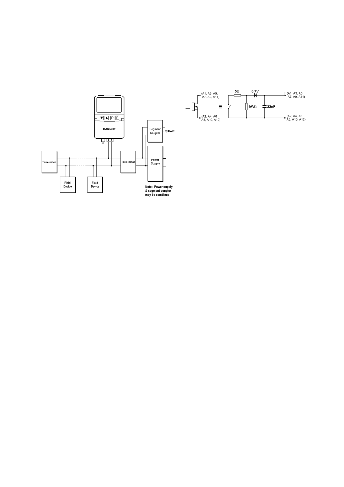
information. The instrument is bus powered so no
additional power supply is required.
The instrument’s communication protocol is shown
on a label inside the terminal cover. The ‘-F’ order
number suffix also indicates the protocol but is not
shown on the instrument identification label.
There is an alternative version of the fieldbus
display, order code BA684DF-P for use on
Profibus PA networks.
This instruction manual describes revision 3
BA684DF-F Foundation fieldbus displays which
were introduced in January 2019. Revision 3
displays have been verified in the FieldComm Labs
as compliant with ITK 6.3.
Instruction manuals for the earlier revision 1 and 2
instruments may be downloaded from the
superseded documentation section of the BEKA
website.
Most of the BA684DF-F display parameters are
configured on-site via the fieldbus. Screen format
selection and alarm configuration is performed
using an internal menu and the instrument's front
panel push buttons.
Up to eight process variables can be displayed
using the two Input Selector function blocks.
The required Device Description files, which may
be downloaded from either the FieldComm or the
BEKA website, depend upon which BA684DF-F
FOUNDATION™ fieldbus display revision is
selected.
Eleven selectable standard display screen formats
enable one, two, three, four or eight process
variables, some with bargraphs to be displayed on
one screen.
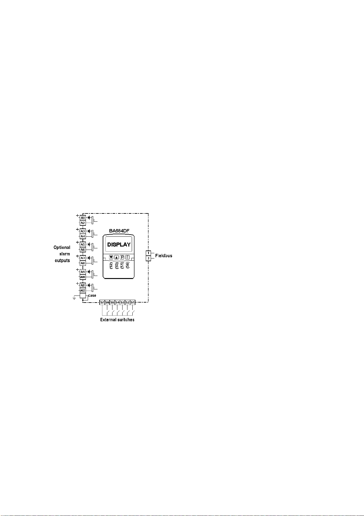
The BA684DF-F FOUNDATION™ fieldbus display
can be supplied with six optional alarm outputs that
may be linked to any of the displayed fieldbus
variables. These alarm outputs are locally
activated from the fieldbus variables and are
configured via the instrument menu and push
buttons. They cannot be controlled via the
fieldbus.
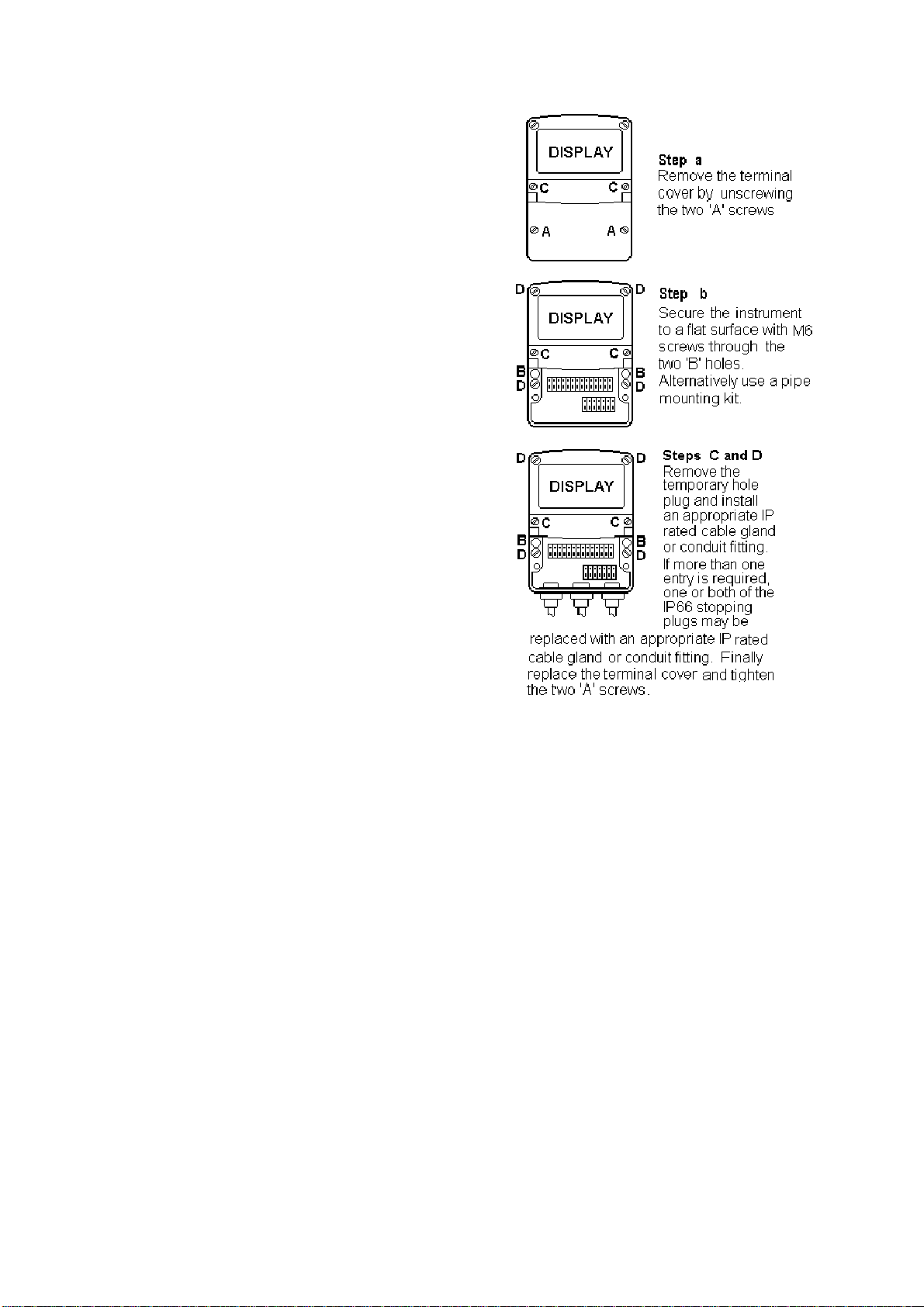
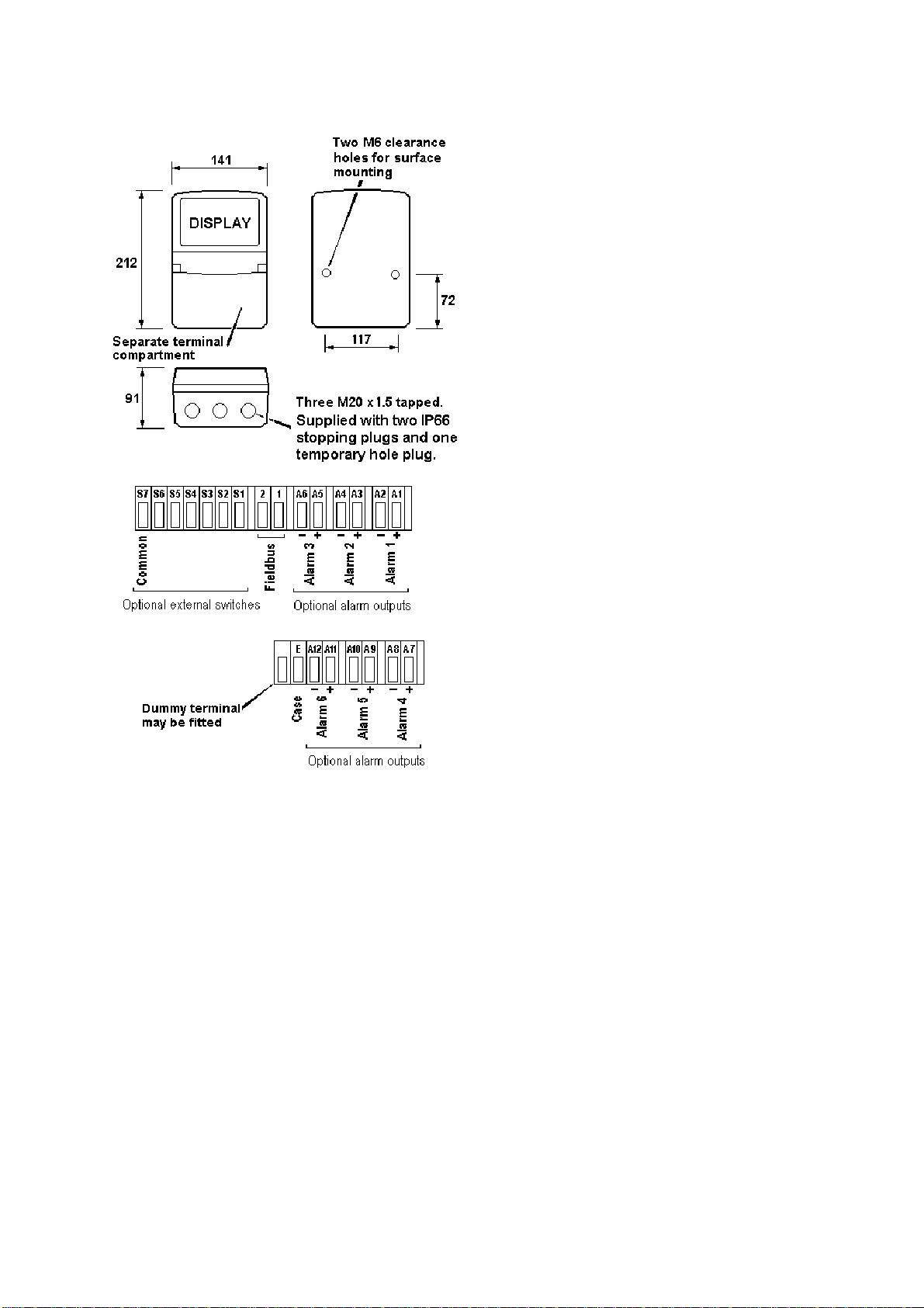
Housed in a robust IP66 glass reinforced polyester
(GRP) enclosure with a toughened glass window,
the BA684DF-F is surface mounting, or may be
pipe mounted using one of the accessory kits.
1.1 Documentation
This instruction manual describes system design,
conditioning and installation of the BA684DF-F
FOUNDATION™ fieldbus display. For detailed
commissioning information please refer to the
FOUNDATION™ fieldbus Interface Guide that can
be downloaded from the BEKA website
www.beka.co.uk
1.2 Version 4.03 firmware
Updated firmware was released in January 2019
which includes the following key features:
11 standard screens
Multiple bargraph limits
Individual input scaling
Two 4-input Input Selector function blocks:
Last variable parameter prevents display of
unused inputs.
Fieldbus compliance verified to ITK 6.3
Option added to remove status text from
single variable screens.
The instrument’s firmware version can be
established using the ‘Unit Info’ function in the
main configuration menu – see section 5.7.8 of this
manual.
3