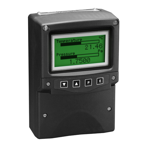
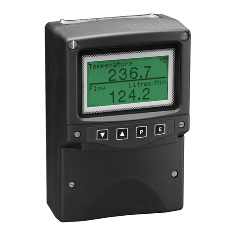
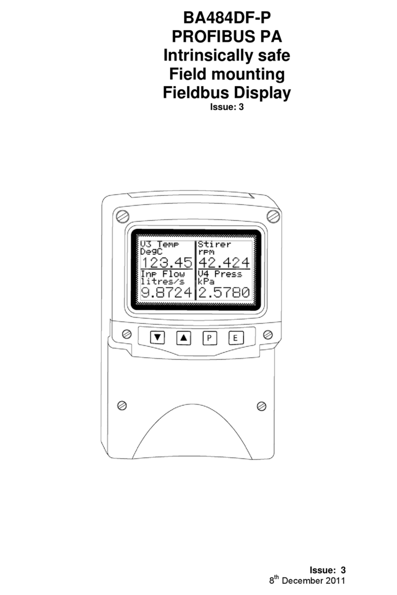
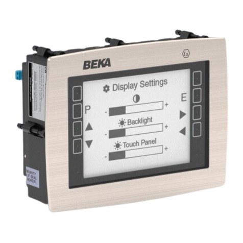
BEKA FOUNDATION BA684DF-F User manual

Issue: 9
6
th
June 2011
BA684DF-F
FOUNDATION™ fieldbus
Field mounting
Display
Issue: 9

2
1. Description
1.1 Documentation
1.2 Version 2.3 firmware
2. Operation
2.1 Controls
3. System Design
3.1 External switches
3.2 Alarm outputs
4. Installation
4.1 Location
4.2 Installation procedure
4.3 EMC
5. Display & Alarm Configuration
5.1 Default configuration
5.2 Accessing the display configuration
menus
5.3 Configurable functions
5.3.1 Screens (Display formats)
5.3.2 Input settings
5.3.3 Tags
5.3.4 Units
5.3.5 Alarms
5.3.5.1 Alarm Summary
5.3.5.2 Alarm Activation
5.3.5.3 Alarm Output
5.3.6 Display
5.3.6.1 Settings
5.3.6.2 Quick Access
5.3.6.3 Access Code
5.3.6.4 Status Text
5.3.6.5 Last Input
5.3.7 Keys
5.3.8 Code
5.3.9 Unit Info
5.3.10 Defaults
5.3.10.1 Display Defaults
5.3.10.2 Interface Board
Defaults.
5.3.10.3 FF Revisions 1 and 2
5.4 Quick Access Menu
6. Programming
7. Maintenance
7.1 Fault finding during commissioning
7.2 Fault finding after commissioning
7.3 Servicing
7.4 Routine maintenance
7.5 Guarantee
7.6 Customer comments
8. Accessories
8.1 Tag plate
8.2 Pipe mounting kits
8.3 FOUNDATION™ fieldbus Interface
Guide.
9. Index
CONTENTS
The BA684DF-F is CE marked to show compliance with the
European EMC Directive 2004/108/EC

3
1. DESCRIPTION
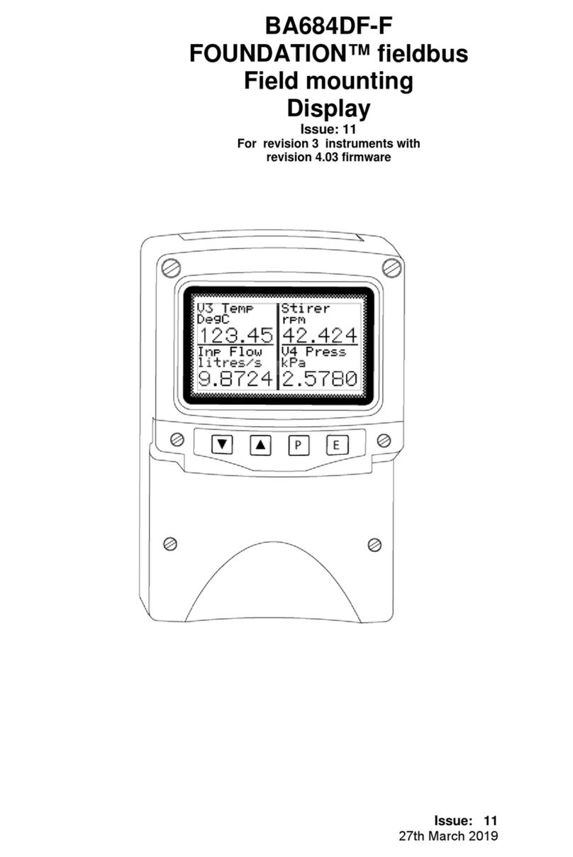
The BA684DF-F FOUNDATION™ fieldbus display
can display up to eight fieldbus process variables,
together with their units of measurement and tag
information. The instrument is bus powered so no
additional power supply is required.
The instrument’s communication protocol is shown
on a label inside the terminal cover. The ‘-F’ order
number suffix also indicates the protocol but is not
shown on the instrument identification label.
There is an alternative version of the fieldbus
display, order code BA684DF-P for use on
Profibus PA networks.
.The BA684DF-F FOUNDATION™ fieldbus display
may be ordered, or configured on-site, with
alternative function blocks allowing use with most
FOUNDATION™ fieldbus hosts.
Revision 1
One Multiple Analogue Output
(1 x MAO)
Revision 2
Two Input Selectors
(2 x IS)
The required Device Description files, which may
be downloaded from either the Fieldbus
Foundation or the BEKA web sites, depend upon
which BA684DF-F FOUNDATION™ fieldbus
display revision is selected.
Eleven selectable standard display formats enable
one, two, three, four or eight process variables,
some with bargraphs to be displayed on one
screen.
The BA684DF-F FOUNDATION™ fieldbus display
can be supplied with six optional alarm outputs that
may be linked to any of the displayed fieldbus
variables. These alarm outputs are locally
activated from the fieldbus variable and are
configured via the instrument menus and push
buttons. They can not be controlled via the
fieldbus.
Housed in a robust IP66 glass reinforced polyester
(GRP) enclosure with a toughened glass window,
the BA684DF-F is surface mounting, or may be
pipe mounted using one of the accessory kits.
1.1 Documentation
This instruction manual describes system design,
conditioning and installation of the BA684DF-F
FOUNDATION™ fieldbus display. For detailed
commissioning information please refer to the
FOUNDATION™ fieldbus Interface Guide that can
be downloaded from the BEKA website
www.beka.co.uk
1.2 Version 2.3 firmware
This manual describes the enhanced features of
BA684DF-F FOUNDATION™ fieldbus displays
employing version 2.3 firmware that was released
in April 2011 following an interim update to version
2.0 in December 2005.
The new features include:
Standard screens increased to 11
Multiple bargraph limits added
Input scaling added
Selectable function blocks added:
Revision 1
1 x MAO (multiple analogue output)
or Revision 2
2 x IS (Input selector)
Option added to remove status text from
single variable screens.
Last variable parameter added to prevent
display of unused inputs.
The instrument’s firmware version can be
established using the ‘Unit Info’ function in the
main configuration menu – see section 5.3.9 of this
manual.
BA684DF-F displays employing version 2.3
firmware are backwards compatible with all earlier
versions of the instrument.

4
2. OPERATION
Fig 1 shows a simplified block diagram of the
BA684DF-F FOUNDATION™ fieldbus display.
When the optional alarms are not fitted, the
instrument only requires a two-wire connection to
the fieldbus.
How much of the BA684DF-F configuration can be
performed via the fieldbus depends upon the
instrument version and the system host.
Parameters that can not be configured via the
fieldbus can be set via the four front panel push
buttons. Menus enable the required standard
display format to be selected and the units of
measurement, plus tag information for each
displayed fieldbus variable to be entered. Each
fieldbus variable may be individually offset and
scaled, and when a standard screen including a
bargraph is selected, the limits of each bargraph
can be set.
The optional alarms are locally activated from the
fieldbus variables and can only be configured and
the setpoints adjusted using the BA684DF-F push
buttons. The alarms can not be configured or
controlled via the fieldbus.
Description files for the BA684DF-F
FOUNDATION™ fieldbus display may be
downloaded from either the Fieldbus Foundation or
from the BEKA associates web sites.
Fig 1 Simplified block diagram of BA684DF-F
2.1 Controls
The user can scroll through the display screens by
operating the ▼or ▲push buttons. The number
of screens available depends upon how the
BA684DF-F FOUNDATION™ fieldbus display has
been configured. If one fieldbus variable per
screen has been configured, eight screens will be
present; if four fieldbus variables per screen have
been configured, only two screens will be
available.
Irrespective of the number of fieldbus variables
assigned to the BA684DF-F, the instrument always
has provision for displaying eight variables.
Unassigned inputs are displayed as zero with a
bad data warning i.e. light digits on a dark
background. The Last Input parameter allows
unused inputs to be skipped when scrolling
through the instrument display screens, see
section 5.3.6.5.
If enabled, operating the Pand ▲push buttons
simultaneously activates the Quick Access Menu,
allowing the user to adjust the display contrast
without providing access to any of the other
configuration parameters. Additional security may
be provided by an optional access code.

5
3. SYSTEM DESIGN
The BA684DF-F FOUNDATION™ fieldbus display
may be connected to any fieldbus segment as
shown in Fig 2, providing it can provide the
additional 25mA required to operate the
instrument.
Fig 2 Fieldbus system
3.1 External switches
For applications requiring operator inputs to be
made by large industrial push buttons, terminals
S1 to S7 allow up to six external switches to be
connected to the Fieldbus Display. When external
switches are connected, the front panel push
buttons may be operated in parallel or disabled –
see section 5.3.7.
The BA684DF-F inputs S1 to S7 for external
switches are not electrically isolated from the
fieldbus terminals, switches and wiring must
therefore be isolated from earth and all other
electrical circuits.
For reliable operation it is recommended that the
cable connecting the Fieldbus Display to the
external switches is less than 5m long.
3.2 Alarm outputs
The BA684DF-F can be supplied with six alarm
outputs that may be linked to any of the displayed
variables. Each alarm output is a galvanically
isolated single pole solid state switch output as
shown in Fig 3.
Fig 3 Equivalent circuit of each switch output
The outputs are polarised and current will only flow
in one direction. Odd numbered terminals should
be connected to the positive side of the supply.
Ron = 5Ω+ 0.7V
Roff = greater than 1MΩ
Note: Because of the series protection diode,
some test meters may not detect a closed alarm
output.
WARNING
These Alarm Outputs should not be used
for critical safety applications such as an
emergency shut down system.
When the BA684DF-F FOUNDATION™ fieldbus
display is disconnected from the fieldbus, or the
fieldbus is de-energised, all the alarm outputs will
open irrespective of how they have been
configured.

6
4. INSTALLATION
4.1 Location
The BA684DF-F FOUNDATION™ fieldbus display
is housed in a robust IP66 glass reinforced
polyester (GRP) enclosure incorporating an
armoured glass window and stainless steel fittings.
It is suitable for exterior mounting in most industrial
environments, including off-shore and waste water
treatment installations. Please consult BEKA
associates if high vibration is anticipated.
The BA684DF-F enclosure is surface mounting.
Accessory kits described in sections 8.2 of this
manual enable the instrument to be mounted onto
a vertical or horizontal pipe.
The field terminals and the two mounting holes are
located in a separate compartment with a sealed
cover allowing the instrument to be installed
without exposing the display assembly.
The BA684DF-F earth terminal is connected to the
carbon loaded GRP case. If the case is not bolted
to a post or structure connected to the plant
potential equalising conductor, the instrument’s
earth terminal should be connected to the potential
equalising conductor.
The BA684DF-F enclosure is supplied with a
bonding plate to ensure electrical continuity
between the three conduit / cable entries.
4.2 Installation Procedure
Fig 4 illustrates the instrument installation
procedure.
a. Remove the instrument terminal cover by
unscrewing the two captive 'A' screws.
b. Mount the instrument on a flat surface and
secure with two M6 screws through the 'B'
holes. Alternatively use one of the mounting
kits described in section 8.2
c. Remove the temporary dust seals from the
three cable entries and install the required
glands, conduit fittings or blanking plugs.
Note: The temporary dust seals fitted for
transit do not maintain the IP66 protection of
the BA684DF-F enclosure.
d. Connect the field wiring to the terminals as
shown in Fig 5.
e. Replace the instrument terminal cover and
evenly tighten the two 'A' screws.
Fig 4 BA684DF-F installation procedure
4.3 EMC
The BA684DF-F complies with the requirements of
the European EMC Directive 2004/108/EC. For
specified immunity, all wiring should be in
screened twisted pairs with the screens connected
to the plant’s potential equalising conductor.

7
Fig 5 Dimensions and terminal connections

8
5. DISPLAY & ALARM CONFIGURATION
In addition to loading the BA684DF-F
FOUNDATION™ fieldbus display Device
Description files onto the system host and defining
up to eight fieldbus variables that are to be
displayed, the instrument display and alarms, if
fitted, have to be configured. How much of this
configuration can be done via the fieldbus depends
upon the instrument version and the system host.
Parameters that can not be configured via the
fieldbus, should be configured via the four front
panel push buttons and the easy to use menu
shown in Fig 6. The optional alarms can only be
configured via the instrument push buttons.
When navigating through the configuration menu,
the push button(s) should be held until the required
screen is displayed.
5.1 Default configuration
Unless otherwise requested at the time of ordering,
BA684DF-F Fieldbus Displays will be supplied
configured as follows:
Keys Both
Display brightness 100%
Display contrast 50%
Quick access menu On
Quick access menu code 0000
Configuration menu
access code. 0000
Screen Single variable
Number format Auto
All alarms Disabled
Alarm activation Good data only
Alarm outputs N/C
Bargraph
Low 0
High 100
Input scaling
Zero offset 0
Gain factor 1
Status text On
Lat input 8
Revision Revision 2
(2 x IS function
blocks)
5.2 Accessing the display configuration
menus
Throughout this manual push buttons are shown in
italics e.g. Por ▲push button, and legends
displayed by the instrument are shown within
inverted commas e.g. 'Enter Access Code'.
Operating the Pand Epush buttons
simultaneously accesses the display configuration
menu. If the BA684DF-F is not protected by an
access code the main menu will be displayed. If
an access code other than the default code 0000
has already been entered, the BA684DF-F will
request that the access code be entered.
Using the ▼or ▲button set the first digit of the
code which will be flashing. Pressing Pwill
transfer control to the next digit, which should be
adjusted in the same way. When all four digits
have been set, pressing the Ebutton will enter the
access code. If the code is correct the main
menu will be displayed, if the code is incorrect
‘Invalid Code’ will be displayed.
When entering an access code, timeout will occur
and the instrument will automatically return to the
operating mode ten seconds after a push button
was last operated. In all other menus, timeout
occurs after sixty seconds.
The structure of the display configuration menu is
shown in Fig 6. Navigation is achieved by
highlighting the required function using the ▼and
▲buttons and then operating the Pbutton to
display the selected function sub-menu, from which
a further selection or adjustment may be made.
Operating the Ebutton moves the display back up
one level.
A flashing highlight indicates that an option or
alphanumeric character may be selected using the
▼and ▲buttons and entered using the Ebutton.
If only one entry or adjustment can be made in a
sub-menu, the display will automatically move up
one menu level when the adjustment is entered. If
more than one adjustment can be made in a sub-
menu, the highlight may be moved to the second
variable using the ▼or ▲button after the first
setting has been entered. Operating the Pbutton
allows the second variable to be adjusted.
When multiple numeric or alpha characters are
adjusted e.g. an alarm setpoint or a tag legend, the
adjustment is made one digit at a time using the ▼
and ▲buttons. After the first flashing digit has
been set as required, the flashing highlight can be
moved to the next digit by operating the Pbutton.
When all digits have been set, operating the E
button will enter the setting.
Following completion of the instrument
configuration, the Ebutton should be operated to
step the display back to the main menu. One more
operation of the Ebutton will then return the
BA684DF-F to the operating mode.

9
5.3 Configurable functions
This section provides an explanation of each
configurable function and should be read in
conjunction with Fig 6.
5.3.1 Screens (Display format)
The BA684DF-F FOUNDATION™ fieldbus display
can display up to eight fieldbus variables that are
identified as IN_1 to IN_8. The fieldbus variable
that each one represents is determined by the
BA684DF-F configuration at the fieldbus system
host - see the FOUNDATION fieldbys™ Interface
Guide.
This sub-menu allows one of eleven standard
display formats containing one, two, three, four or
eight fieldbus variables some with bargraphs as
shown below.
The ‘Text Display’ option which enabled custom
formats to be created is depreciated i.e. still
available but no longer actively supported.
.
One variable
Two variables
Four variables
Eight variables
One variable + horizontal bargraph
Two variables + horizontal bargraphs
One variable + vertical bargraph
Two variables + vertical bargraphs
Three variables + vertical bargraphs
Four variables + vertical bargraphs
Eight variables + horizontal bargraphs
5.3.2 Input Settings
Note: Only included in Revision 1 instruments.
Omitted from Revision 2 instruments because these
parameter can be easily configured in the Display
Transducer Block.
The Input Setting function is divided into two
groups of sub-functions. The first, ‘BarLimits Src’
is included to maintain backwards compatible with
earlier firmware issues in which fieldbus variables
IN_7 and IN_8 were used to define all the bargraph
limits. This reduced the number of fieldbus
variables that could be displayed with bargraphs
from eight to six.

10
Version 2.3 firmware includes the improved ‘Per
Input’ option that enables the lower and upper
limits of a bargraph for each of the eight fieldbus
variables to be defined via the front panel push
buttons. It is recommended that ‘Per Input’ option
be used for new installations.
In addition to defining individual limits for up to
eight bargraphs, the second group of sub-functions
enables the decimal point position for each display
to be defined. Each of the eight fieldbus inputs
may also be offset and scaled before being
displayed which allows variables to be displayed in
alternative units of measurement.
Display = (Gain x Fieldbus variable) + Offset
The sub-functions for each input are:
‘Offset’ Adds a positive or negative offset to
the fieldbus variable before it is
displayed.
‘Gain’ Multiplies the fieldbus variable by a
factor before it is displayed.
‘Bar Lo’ Defines the bargraph lower limit
‘Bar Hi’ Defines the bargraph higher limit
‘Format’ Defines the position of the displayed
decimal point.
Six options are available:
Auto: Max resolution with selected
display format.
4 DP 4 digits on right of decimal point
3 DP 3 digits on right of decimal point
2 DP 2 digits on right of decimal point
1 DP 1 digit on right of decimal point
0 DP No decimal point
The total number of display digits available
depends upon the display screen selected – see
5.3.1
Standard
Screen Description Digits
1 1 variable 5, 7, 11 or 17*
2 2 variables 7
3 4 variables 5
4 8 variables 5
5 1 variable + H bar 5, 7, 11 or 17*
6 2 variables + H bars 7
7 1 variable + V bar 6
8 2 variables +V bars 4
9 3 variables + V bars 6
10 4 variables + V bars 4
11 8 variables + H bars 5
* Font automatically resizes in auto mode
If a negative number is likely to be displayed, a
digit must be allocated for the negative sign. If the
display overanges all the digits will display ‘?’.
For all options leading zeros, apart from the zero in
front of a decimal place, are automatically
suppressed.
5.3.3 Tags
Note: Only included in Revision 1 instruments.
Omitted from Revision 2 instruments because tags can
be easily defined in the Display Transducer Block.
Each of the eight fieldbus variables may be
displayed with an individual tag that can contain up
to sixteen alphanumeric characters. This menu
allows these tags to be entered. After selecting the
required variable, the tag legend is entered
character by character using the ▼and ▲push-
buttons. Numbers, upper & lower case letters and
symbols are available.
5.3.4 Units
Note: Only included in Revision 1 instruments.
Omitted from Revision 2 instruments because units of
measurement can be easily defined in the Display
Transducer Block.
Each of the eight fieldbus variables may be
displayed with units of measurement that can
contain up to eight alphanumeric characters. This
menu allows these units of measurement to be
entered. After selecting the required variable, the
unit of measurement is entered character by
character using the ▼and ▲push-buttons.
Numbers, upper & lower case letters and symbols
are available.
5.3.5 Alarms
Note: Alarm menus are only included when the
BA684DF-F is fitted with optional alarm outputs.
Outputs are locally activated from the fieldbus
variables and are configured via the instrument
menus and push buttons. They can not be
controlled via the fielsbus.
Each of the six alarms may be linked to any one of
the eight fieldbus variables displayed by the
BA684DF-F. Each alarm output can be
conditioned to function as a high or a low alarm, or
as a combined high and low alarm. The output
can be conditioned as normally open ‘N/O’ or
normally closed ‘N/C’ in the non-alarm condition.
Irrespective of settings, all alarm outputs will be
open when the instrument is not powered from the
fieldbus.
When an alarm is activated, the associated
fieldbus variable display flashes, i.e. alternates
between dark figures on a light background and
light figures on a dark background.
There are eight alarm-conditioning sub-menus.
11
5.3.5.1 Alarm Summary
Shows to which fieldbus variable each alarm is
linked and how each alarm has been conditioned.
i.e. high, low, or combined high & low alarm with a
normally open or closed output. No adjustments
can be made via this sub-menu.
5.3.5.2 Alarm Activation
Fieldbus variables that have not been validated are
displayed with dark characters on a light
background, and some screen formats also contain
a status indication. This sub-menu allows the
alarm outputs to be conditioned so that they only
operate with validated fieldbus data, or to operate
irrespective of data validity.
5.3.5.3 Alarm Output
There is a separate sub-menu for each of the six
alarm outputs; these link the alarm to one of the
displayed fieldbus variables and define the alarm
function and the setpoints.
To link the alarm to a displayed variable, position
the highlight over the ‘IN_n’ field, press Pand
using the ▼or ▲button select the required input
source. Enter the selection by pressing the E
button.
Each alarm output can be N/O or N/C in the non-
alarm condition. To change the setting, position
the highlight over the ‘N/O’ or ‘N/C’ field, press P
and use the ▼or ▲button to toggle the setting.
Enter the selection by pressing the Ebutton.
Each alarm output has three functions that can be
independently enabled to condition the output as a
low or high alarm, or as a combined low and high
alarm, either with or without hysteresis.
The required functions can be individually enabled
by positioning the highlight over the Enb/Dis
(Enabled/Disabled) column, pressing Pand
toggling the function to the required state, then
entering the selection by pressing the Ebutton.
Alarm setpoints are entered digit by digit. Place
the highlight over the setpoint to be adjusted and
press P; the flashing digit to be adjusted may then
be selected by again pressing P. When all the
digits have been adjusted, operating the Ebutton
enters the value and moves the menu up one level.
The function of all alarms may be reviewed from
the alarm summary menu - see 5.3.5.1.
5.3.6 Display
5.3.6.1 Settings
The backlight brilliance and display contrast are
adjustable from this sub-menu.
5.3.6.2 Quick Access
This sub-menu enables the Quick Access Menu
which is described in sections 2.1 and 5.4 When
enabled, an operator can adjust the display
contrast and backlight brilliance without having
access to any other conditioning menus.
5.3.6.3 Access Code
Defines a four digit alphanumeric code that must
be entered to gain access to the Quick Access
Menu. Alpha characters are case sensitive.
Default code 0000 allows direct access without a
code.
5.3.6.4 Status Text
The two single variable screens 1 and 4 will show
the status of the FOUNDATION™ fieldbus variable
as ‘Good’ or ‘Bad’ if the Status Text function is
activated.
5.3.6.5 Last Input
This function allows the maximum number of
FOUNDATION™ fieldbus variables to be defined
so that unused inputs are skipped when the display
is scrolled in the operating mode.
5.3.7 Keys
The function of the front panel push buttons may
be transferred to four of the six optional external
push buttons, with or without disabling the
BA684DF-F front panel push buttons. The table
below shows the function of the BA684DF-F front
panel and the external push buttons for each of the
four options that may be selected in the Keys sub-
menu.
For applications where the instrument is only
displaying 1, 2, 3, 4 or 8 variables on a single
screen, it is recommended that external buttons
are selected but not fitted. This will disable the
instrument front panel buttons, but still provide
access to the configuration menu, which may be
protected by a security code.

12
5.3.8 Code
Defines the four digit alphanumeric code that must
be entered to gain access to the instrument
configuration menus. Alpha characters are case
sensitive. Default code 0000 allows direct access
without a code.
5.3.9 Unit Info
Displays the instrument model number and the
software version.
5.3.10 Defaults
This function enables the display and interface
board factory defaults to be restored. The
function blocks (Revision 1 or 2) should be
selected to suit the system host.
5.3.10.1 Display Defaults
This function restores the display defaults defined
in section 5.1. CAUTION
Existing settings can not be recovered
after this function has been used.
5.3.10.2 Interface Board Defaults
This function restores the Fieldbus Interface Board
factory defaults. CAUTION
Do not use this function when the
BA684DF-F is connected to an
operational fieldbus, as communication
will be terminated.
5.3.10.3 Revisions 1 and 2
Unless specified at the time of ordering, BA684DF-
F- FOUNDATION™ fieldbus displays will be
supplied as Revision 2 instruments. i.e. two input
selector function blocks (2 x IS).
The BA684DF-F can be converted to a Revision 1
instrument using the Default menu. i.e one
multiple analogue output function block (1
x MAO).
The BA684DF-F FOUNDATION™ fieldbus display
revision should be chosen so that the fieldbus
function blocks selected are supported by the
system host.
To change the BA684DF-F-F revision, highlight the
required revision in the ‘Restore Defaults’ menu
and follow the screen prompts until ‘Defaults
Loaded Now power cycle the unit’ is displayed.
To complete the installation remove the BA684DF-
F power supply for a few seconds, when power is
restored the instrument will restart with the
selected revision.
5.4 Quick Access Menu
The Quick Access Menu allows an operator to
adjust the backlight brilliance and the display
contrast without having access to the other
configuration parameters.
The quick access menu is accessed by operating
the Pand ▲push buttons simultaneously. If the
Quick Access Menu is not protected by an access
code the contrast and brilliance controls will be
displayed immediately. If an access code other
than the default code 0000 has already been
entered, the BA684DF-F will request that the
access code be entered.
The display backlight brilliance is adjusted using
the ▼and ▲push buttons. Operating the Ppush
button will transfer control to the display contrast
adjustment. When both are set as required,
operating the Ebutton will store both settings and
return the instrument to the operating mode.

13

14
6. PROGRAMMING
The ‘Text Display’ option which enabled custom
formats to be created is depreciated i.e. still
available but no longer actively supported.
7. MAINTENANCE
7.1 Fault finding during commissioning
If a BA684DF-F FOUNDATION™ fieldbus display
fails to function during commissioning the following
procedure should be followed:
Symptom Cause Check:
No Display Fieldbus not
powered 9 to 32V between
terminals 1 & 2.
No variables Fieldbus not
configured
BA684DF-F does
not have correct
protocol
Instrument
configuration at
host
That BA684DF-F
protocol is same
as fieldbus.
i.e. Fieldbus
Foundation or
Profibus PA.
Wrong variable
displayed Wrong screen
selected Other screens by
operating Up or
Down button
Display showing
‘?????’ Display
overrange Number format
see section 5.3.2
No backlight Brilliance turned
down Setting in display
menu
Low or excessive
contrast Incorrect contrast
setting Setting in display
menu
Displayed
variable is
inverted
i.e. light digits on
dark background
Variable has
‘bad’ status Configuration
and instrument
supplying
variable
Displayed
variable is
flashing
Associated alarm
has been
activated
Setpoints
Bargraph on
standard display
format is shown
dotted
Displayed
fieldbus variable
is outside
bargraph limits or
data is ‘bad’
Bargraph limits
see section 5.3.5
7.2 Fault finding after commissioning
ENSURE PLANT SAFETY BEFORE
STARTING MAINTENANCE
If a BA684DF-F fails after it has been functioning
correctly, the table shown in section 7.1 may help
to identify the cause of the failure.
If this procedure does not reveal the cause of the
fault, it is recommended that the instrument is
replaced.
7.3 Servicing
We recommend that faulty BA684DF-F
FOUNDATION™ fieldbus display are returned to
BEKA associates or to our local agent for repair.
7.4 Routine maintenance
The mechanical and electrical condition of the
instrument should be regularly checked. Initially
annual inspections are recommended, although
the inspection frequency should be adjusted to suit
the environmental conditions.
7.5 Guarantee
Instruments which fail within the guarantee period
should be returned to BEKA associates or our local
agent. It is helpful if a brief description of the fault
symptoms is provided.
7.6 Customer comments
BEKA associates is always pleased to receive
comments from customers about our products and
services. All communications are acknowledged
and whenever possible, suggestions are
implemented.

15
8. ACCESSORIES
8.1 Tag plate
The BA684DF-F can be supplied with a blank or
custom engraved stainless steel plate secured by
two screws to the front of the instrument enclosure.
This plate can accommodate:
1 row of 9 alphanumeric characters 10mm high
or 1 row of 11 alphanumeric characters 7mm high
or 2 rows of 18 alphanumeric characters 5mm
high
8.2 Pipe mounting kits
Two pipe mounting kits are available for securing
the BA684DF-F to a horizontal or vertical pipe.
BA392D Stainless steel bracket secured by two
worm drive hose clips for 60 to 80mm
outside diameter pipes.
BA393 Heavy duty stainless steel bracket
secured by a single 'V' bolt. Will clamp
to any pipe with an outside diameter
between 40 and 80mm.
8.3 FOUNDATION™ fieldbus Interface Guide
The BEKA FOUNDATION™ fieldbus Interface
Guide which may be downloaded from the BEKA
website at www.beka.co.uk contains configuration
information for all BEKA FOUNDATION™ fieldbus
products.

16
9. INDEX
Subject Section
Alarms 5.3.5
Activation 5.3.5.2
Output 3.2; 5.3.5.3
Summary 5.3.5.1
Backlight 5.3.6.1
Bargraph limits 5.3.2
Configuration menu Fig 6
Controls 2.1
Code 5.3.8
Decimal points 5.3.2
Default settings 5.1; 5.3.10
Display 5.3.6
Access code 5.3.6.3
Settings 5.3.6.1
Quick access 5.3.6.2
EMC 4.3
External switches 3.1; 5.3.7
Fault finding
During commissioning 7.1
After commissioning 7.2
Guarantee 7.5
Input scaling 5.3.2
Installation 4.
Interface Guides 8.4
Keys 5.3.7
Last Input 5.3.6.5
Location 4.1
Maintenance 7.
Routine 7.4
Number Format 5.3.2
Subject Section
Pipe mounting kits 8.2
Profibus PA 1
Quick access menu 5.3.6.2; 5.4
Revisions 1 & 2 5.3.10.3
Servicing 7.3
Screens (display format) 5.3.1
Status Text 5.3.6.4
Tags 5.3.3
Tag plate 8.1
Terminal numbers Fig 5
Units (of measurement) 5.3.4
Unit Info (firmware version) 5.3.9
Other manuals for FOUNDATION BA684DF-F
1
Table of contents
Other BEKA Monitor manuals

BEKA
BEKA BA684DF User manual

BEKA
BEKA BA488C Operating instructions

BEKA
BEKA BA3101 User manual

BEKA
BEKA BA688CF User manual

BEKA
BEKA FOUNDATION BA684DF-F User manual

BEKA
BEKA BA688CF-P User manual

BEKA
BEKA BA688CF-F User manual

BEKA
BEKA FOUNDATION BA488CF-F User manual

BEKA
BEKA BA538C User manual

BEKA
BEKA FOUNDATION BA484DF-F User manual