Beko METPOINT PRM SP11 User guide

EN - English
Instructions for installation and operation
Pressure transducer METPOINT®PRM
SP1
1
10-054

2 METPOINT®SP11
Dear customer,
Thank you for deciding in favour of the METPOINT®PRM SP11 pressure transducer. Please read these
installation and operating instructions carefully before mounting and starting up the pressure transducer and
follow our directions.
Perfect functioning of the pressure transducer can only be guaranteed when the provisions and notes stipu-
lated here are strictly adhered to.

Inhalt
METPOINT®SP11 3
Contents
1Pictograms and symbols ........................................................................................................................ 4
2Signal words in accordance with ISO 3864 and ANSI Z 535.................................................................4
3General information................................................................................................................................5
4Safety instructions ..................................................................................................................................6
5Proper use.............................................................................................................................................. 7
6Exclusion from the field of application....................................................................................................7
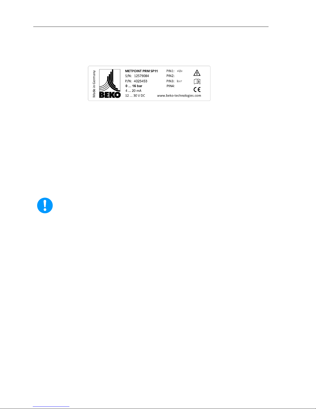
7Type plate...............................................................................................................................................8
8Technical data ........................................................................................................................................9
9Dimension drawings .............................................................................................................................12
10 Function................................................................................................................................................14
11 Installation ............................................................................................................................................15
11.1 Installation instructions .........................................................................................................................15
11.2 Preparing the thread at the measurement point ..................................................................................16
11.3 Installation example for connections in accordance with EN 837-1 with a cylindrical thread ..............16
12 Electrical installation.............................................................................................................................17
12.1 Pin assignment PRM SP11, 2-wire ......................................................................................................18
13 Maintenance and calibration ................................................................................................................20
13.1 Cleaning/decontamination....................................................................................................................21
14 Scope of delivery..................................................................................................................................22
15 Accessories ..........................................................................................................................................23
16 Dismantling and diposal .......................................................................................................................24
17 Trouble shooting and fault removal......................................................................................................25
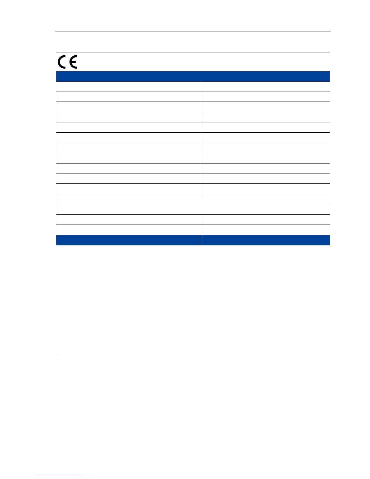
18 Declaration of conformity .....................................................................................................................26
19 Index.....................................................................................................................................................27

Pictograms and symbols
4 METPOINT®SP11
1 Pictograms and symbols
Observe the installation and operating instructions
General advice
Observe the installation and operating instructions
(on the type plate)
General danger symbol (danger, warning, caution)
Use protective gloves
2 Signal words in accordance with ISO 3864 and ANSI Z 535
Pos: 25 /B e k o Tec hni s che Do k u me nt ati on/Si c her heit /Si g nalw ort e I SO + AN SI @ 0\mod_1213340310421_6.docx@8739 @ @ 1
Danger! Imminent hazard
Consequences of non-observance: serious injury or death
Warning! Potential hazard
Consequences of non-observance: possible serious injury or death
Caution! Imminent hazard
Consequences of non-observance: possibly injury or property damage
Notice! Potential hazard
Consequences of non-observance: possibly injury or property damage
Important! Additional advice, info, hints
Consequences of non-observance: disadvantages during operation and maintenance, no dan-
ger

General information
METPOINT®SP11 5
3 General information
Warning!
Risk of injury when used incorrectly!
Prior to the mounting, start-up, and operation of the pressure transducer, it must be en-
sured that the device was correctly chosen with regard to the measuring range, design and
specific measurement conditions. In the event of non-observance, severe personal injury
and/or damage to materials may occur.
Warning!
Risk of injury in the event of insufficient qualifications!
Improper use can lead to significant personal injury and material damage.
All of the activities described in these operating inst
ructions must only be carried out by
qualified personnel with the qualifications described hereinafter.
Qualified personnel
Due to the specific training and knowledge concerning the measuring and control technology, and due to
their experience and knowledge of the country-specific provisions, standards in force and directives, qualified
personnel are capable of carrying out the described work and of independently identifying the possible risks.
Special employment conditions require further corresponding knowledge, e.g. regarding aggressive media.
Please check, prior to reading the operating instructions, whether or not these instructions cor-
respond to the device. Read these installation and operating instructions carefully prior to any
intervention regarding the METPOINT®PRM. The operating instructions must be accessible at
all times at the place of application of the device.
If you have any queries regarding these instructions, please contact BEKO TECHNOLOGIES
GMBH.
Installation works must exclusively be carried out by authorised and qualified personnel. Prior to
undertaking any measures, the qualified personnel shall read up on the device by carefully
studying the operating instructions. The operator of the products is responsible for the adher-
ence to these provisions. The respective directives in force apply to the qualification and exper-
tise of the qualified personnel.
For safe operation, the device must only be installed and operated in accordance with the indi-
cations in the operating instructions. In addition, the national and operational statutory provi-
sions and safety regulations, as well as the accident prevention regulations re
quired for the
respective case of application, need to be observed during employment. This applies according-
ly when accessories are used.

Safety instructions
6 METPOINT®SP11
4 Safety instructions
Danger!
Compressed air!
Risk of serious injury or death through contact with quickly or suddenly escaping compressed air
or through bursting plant components.
Measures
•Do not exceed the max. operating pressure (see type plate)!
•Only use pressure-resistant installation material!
•Make sure that no persons or objects can be hit by emerging compressed
air!
Danger!
Inadmissible operating parameters!
Under-running or exceeding the limit values involves risks for persons and the material, and mal-
function and service failures may occur.
Measures
•Make sure that the pressure transducer is operated only within the permissible limit values that are indi-
cated on the type plate and in the technical data.
•Exact compliance with the performance data of the pressure transducer in connection with the case of
application.
•Carry out service and calibration measures at regular intervals.
Further safety advice
•During installation and operation, the national regulations and safety instructions in force also need to
be observed.
•The pressure transducer must not be employed in hazardous areas.
Additional instructions
•Do not overheat the device!
•The pressure transducer must not be disassembled!
Measures
•Only use the device with the media that are listed in the data sheet and in the technical data.
Note:
The resistance at the double permissible max. operating pressure is confirmed.
For further information, please refer to the enclosed technical data sheet.
Caution!
Damage possible!
Using the pressure transducer with corrosive media involves the risk of premature
technical failure.

Proper use
METPOINT®SP11 7
5 Proper use
The METPOINT®PRM pressure transducer detects the relative pressure (gauge pressure) in gaseous and
liquid media and transforms this measured value into a linear output signal 4 … 20 mA or 0 … 10 V.
Pressure transducers transform the physical pressure into a pressure-proportional electrical signal. De-
pending on the version, there are different measuring principles which form the basis of the pressure moni-
toring.
The METPOINT®PRM pressure transducer is exclusively designed and constructed for the proper applica-
tion purpose that is described herein and must be used correspondingly.
A check in order to ascertain whether or not the device is suitable for the chosen employment must be car-
ried out by the user. It must be ensured that the medium is compatible with the components which come into
contact with it. The technical data listed in the data sheet are binding.
Improper handling or operation outside the technical specifications is impermissible. Claims of any kind on
the basis of improper use are excluded.
6 Exclusion from the field of application
•The device is not suitable for use in hazardous areas.
•The device is not suitable for application with corrosive gases.
•Corrosive fluids must not be conducted through the pressure transducer.
•Improper handling or operation outside the technical specifications.

Type plate
8 METPOINT®SP11
7 Type plate
The type plate is on the housing. It includes all the important data regarding the METPOINT®PRM pressure
transducer which must be communicated to the manufacturer or supplier upon request.
METPOINT®PRM Product designation
S/N: Serial number
P/N: Item number
0 … 16 bar Measuring range
4 … 20 mA Output signal
12 … 30 V DC Supply voltage
PIN 1: Power supply (Uv+)
PIN 2:
PIN 3: Current output (Iout)
PIN 4:
Note:
Never remove, damage, or obliterate the type plate!

Technical data
METPOINT®SP11 9
8 Technical data
General indications
Model designation PRM SP11
Measuring principle Stainless-steel thin film technology
Measured parameter Overpressure (gauge pressure)
Output signal, type PRM SP21 4 ... 20 mA, analogue, 2-wire
Measuring range 0 … 16 bar
Overload pressure limit 32 bar
Burst pressure 125 bar
Process medium 1Gases/fluids
Temperature-compensated range 0 … 60 °C
Reference conditions EN 61298-1
Process connection (connection pin acc. to EM 837-1) G¼ B
Weight 105 g
Service life 10 million load alterations
Protection class acc. to EN 60529 2IP 67
Nonlinearity after limit point setting 3≤ ± 0.15% MBE 5
Max. error of measurement
4
≤ ± 0.5% MBE
5
1Process medium
Compressed air, nitrogen, water, oil, and other fluids of group 2 according to Article 9, Clause2.2 of the
PED 97/23/EC. Group 2 comprises fluids which are not toxic, flammable, potentially explosive, and fire-
promoting. The process medium must be compatible with the materials 1.4404 and 1.4548.
2The indicated protection classes according to EN 60529 only apply when connected, with a mating
connector with a corresponding protection class.
3Nonlinearity after the limit point setting, according to EN 61298-2
As regards the limit point setting, the reference line passes through the initial and end point
of the measured characteristic curve.
4Max. error of measurement according to EN 61298-2
including nonlinearity, hysteresis, non-repeatability, and error of measurement of the measuring range final
value. Calibrated at a vertical installation position with a downward process connection.
5MBE = Measuring range final value.

Technical data
10 METPOINT®SP11
Materials
Sensor element (in contact with the medi-
um) 1.4548
Process connection (in contact with the
medium) 1.4404, EN 10272, EN 10088-3
Housing 1.4404, EN 10272, EN 10088-3
Mounting connector CuZn, Au, PA, FKM / EPDM
Permissible temperature ranges
Process-medium temperature -40 … +85 °C
Ambient temperature during operation -25 … +85 °C
Storage and transport temperature -40 … +85 °C
Ambient humidity +20 … +95 % relative humidity, non-condensing
Electrical specifications PRM SP11
Supply voltage
1
UV
12 ... 30 V DC
Max. power consumption dur-
ing nominal operation PRM SP11 (4 … 20 mA) 630 mW
Current consumption 2, 3
during nominal operation PRM SP11 (4 … 20 mA) Signal current, max. 21 mA
Load (load resistance) RLPRM SP11 (4 … 20 mA) RL= 571 Ω at 24 V DC
Resistance to short-circuiting Permanent
Reverse voltage protection
4
Available
Insulation resistance
> 100 M
Ω
at 500V DC
Voltage proof 500 V AC
Overvoltage arrester 36 DC
V AC = V alternating current
V DC = V direct current
1The nominal value of the supply voltage is 24 V DC.
Supply to the pressure transducer should be implemented with a stabilised, short-circuit-protected power
supply that is protected against overvoltage.
The energy supply to the pressure transducer must come from a source with an energy-limited electrical
circuit (10A max./ 30V max.) and a protective separation from the network. See EN 61010-1, Clause 9.4.
2The indications are related to nominal operation.
3The protection against excess current is realised via a resettable PTC fuse.
4Reverse voltage protection. In the event that the connections are interchanged, the sensor will not be dam-
aged, but the sensor has no function.

Technical data
METPOINT®SP11 11
Mechanical stresses
Vibration resistance/vibrations according to EN 60068-2-6 25 … 2000 Hz, 20 g, sine
Mechanical shock resistance according to EN 60068-2-27 50 g, 11 ms, half-sine
CE conformity
Pressure Equipment Directive
1
97/23/EC
EMC Directive 2004/108/EC
EMC immunity to interference, industrial field EN 61326-1 & EN 61326-2-3
EMC emitted interference (emission), group 1, class B EN 61326-1
CE labelling according to the EMC Directive 2004/108/EC
Electrical connections
Connector (cable box) according to EN 61076-2-101 M12 x1 (4-pole)
Type of connection Screw terminals
Wire cross-section max. 0.75 mm
2
(AWG 18)
Grommet 4 … 6 mm
Protection class IP 67 according to EN60529
1For gases and fluids of fluid group 2, the requirements according to Article 3, Clause 3 (good engineering
practice) are met.

Dimension drawings
12 METPOINT®SP11
9 Dimension drawings
Dimensions PRM SP11

Dimension drawings
METPOINT®SP11 13
Dimensions and connections PRM SP11
Connection adapter, R¼ and ¼-NPT, width A/F (German "Schlüsselweite") 27
Standards for threads
Straight pipe thread (internal and external screw thread) for a non-sealing connection in the thread
Short symbol G, according to ISO 228-1
Tapered external pipe thread for a sealing connection in the thread
Short symbol R, according to EN 10026-1
Tapered external pipe thread for a sealing connection in the thread
Short symbol NPT, according to ANSI/ASME B1.20.1

Function
14 METPOINT®SP11
10 Function
The METPOINT
®
pressure transducer of the PRM-SP series de-
tects the relative pressure (gauge pressure) in gaseous and liq-
uid media and transforms this measured value into a linear, pres-
sure-proportional electrical output signal of 4 … 20 mA or 0 … 10
V.
As regards the METPOINT®PRM, sensors of the thin-film tech-
nology are employed.
The body and membrane consist of 1.4548 stainless-steel materi-
al. On the membrane side that faces away from the medium, insu-
lation layers, strain gauges, compensating resistors, and conduc-
tors are applied with a combination of chemical and physical
methods, and are photolithographically structured through etch-
ing. The layers of the resistors and electrical
conductors applied on the sensor are considerably thinner than a
micrometer and are, therefore, called thin-film resistors.
Due to the materials used, the metal thin-film sensor boasts
very good resistance to many media and it is insensitive to
shocks and vibration impacts.
Since the employed materials are easily weldable, the sensor is
hermetically welded onto the pressure connection, without need-
ing additional sealing material.

Installation
METPOINT®SP11 15
11 Installation
11.1 Installation instructions
Warning!
Risk of injury in the event of insufficient qualifications!
Improper use can lead to significant personal injury and material damage.
All of the activities described in these operating instructions must only be carried out by qualified
personnel with the qualifications described hereinafter.
Qualified personnel
Due to the specific training and knowledge concerning the measuring and control technology, and due to
their experience and knowledge of the country-specific provisions, standards in force and directives, qualified
personnel are capable of carrying out the described work and of independently identifying the possible risks.
Special employment conditions require further corresponding knowledge, e.g. regarding aggressive media.
Danger!
Compressed air!
Risk of serious injury or death through contact with quickly or suddenly escaping compressed air
or through bursting and/or unsecured plant components.
Measures:
•Only carry out installation works when the system is pressureless.
•Only use pressure-resistant installation material.
•Do not exceed the max. operating pressure (see type plate).
•Check the installation point for tightness subsequent to installation.
Warning!
Risk of injury through temperature!
Risk of injury through the contact with very high or low temperatures.
Measures:
•Prior to installation or removal of the pressure transducer, carry out a temperature compensation or
wear protective gloves.
Note:
It is imperative to observe all of the listed hazard and warning notes.
Please also observe all the provisions and instructions regarding the occupational safety and fire
at the respective point of installation.
As a matter of principle, only use suitable tools and material in a proper
condition.
Bear in mind that condensates can contain aggressive and harmful components.
Therefore, avoid contact with the skin.
Caution!
Malfunction at the pressure transducer!
Through incorrect installation, malfunctions may occur at the METPOINT®PRM pressure trans-
ducer. These can lead to incorrect measuring results and to misinterpretations.

Installation
16 METPOINT®SP11
11.2 Preparing the thread at the measurement point
In order to install the pressure transducer, a receiving thread is required at the measuring point. The latter
must already show the following specifications or must be prepared correspondingly:
11.3 Installation example for connections in accordance with EN 837-1 with a cylindrical thread
In order to seal the process connection (1) with a cylindrical thread (3) at the sealing surface (4), flat gaskets
(2) are employed.
Installation steps
•Use a suitable gasket for the sealing (2), e.g. a copper gasket, corresponding to the measuring medium
and the pressure to be measured.
•The sealing surface (4) of the part to be received must have a perfect, clean, and undamaged surface.
•Manually screw the pressure transducer into the receiving thread.
•Do not twist the thread turns during the screwing-in.
•Only screw-in or unscrew the device via the spanner flats using a suitable tool, and with the specified
torque. The correct torque depends on the dimension of the process connection and on the used gasket
(shape/material). During the screwing-in or unscrewing, do not use the housing as a working surface.
•Subsequently, tighten the threaded-end fitting with the open-end spanner (for G¼" max. 20 Nm).

Electrical installation
METPOINT®SP11 17
12 Electrical installation
The nominal value for the supply voltage for the electrical installation is 24 V DC.
Supply of the METPOINT®PRM SP11 must be implemented with a stabilised, short-circuit-protected power
supply that is protected against overvoltage. The energy supply must come from a source with an energy-
limited electrical circuit (10 A max./ 30 V max.) and a protective separation from the network. See also EN
61010-1, Clause 9.4.
Prior to the installation and start-up, the maximum load resistance must be observed. With a nominal value
of the supply voltage of 24 V DC, the max. load resistance is 571 Ω. With a supply voltage that deviates from
24 V DC, the max. load resistance can be calculated according to the following formula:
RL ≤(Uv- 12 V) / 0.021 A [Ω]
Warning!
Risk of injury in the event of insufficient qualifications!
Improper use can lead to significant personal injury and material damage.
All of the activities described in these operating instructions must only be carried out by
qualified personnel with the qualifications described hereinafter.
Qualified personnel
Due to the specific training and knowledge concerning the measuring and control technology, and due to
their experience and knowledge of the country-specific provisions, standards in force, and directives, quali-
fied personnel are capable of carrying out the described work and of independently identifying the possible
risks.
Special employment conditions require further corresponding knowledge, e.g. regarding aggressive media.

Electrical installation
18 METPOINT®SP11
12.1 Pin assignment PRM SP11, 2-wire
Pin Function Description Conductor colouring
PIN-1 +UVPositive (+) connection of the supply voltage Brown
PIN-2 Not used
PIN-3 I OUT Current output Blue
PIN-4 Not used
Connection diagram PRM 11, 2-wire system, current output 4 … 20 mA
Notes:
The output of the current signal takes place at PIN-3 of the four-pole connector. The METPOINT® PRM SP11
pressure transducers are supplied ex works with a current output of 4 … 20 mA. The following
scaling was configured in the factory:
4 mA = 0 bar (g)
20 mA = 16 bar (g)

Electrical installation
METPOINT®SP11 19
The following advice applies to the connection:
Shielding is implemented via the shield ring of the connector. The preconditions for proper shielding are that
the respective connector is made of metal and that the shield has the shape of a braid. The shielding must
be earthed at one end.
Connector, M12 x 1, 4-pole, a-coded
Arrangement of the poles plug
View transmitter side
Arrangement of the poles - fe-
male connector
View female connector side
Arrangement of the poles female
connector
View screwing side
The cable must be assembled as follows:
1. Push the components of the plug connector over the cable
2. Cut the cable jacket by 20 mm in length
3. Cut the conductor sheath by 5 mm in length
4. Introduce the cable into the connector according to the pin assignment
5. Assemble/screw together the components of the connector

Maintenance and calibration
20 METPOINT®SP11
13 Maintenance and calibration
The perfect and safe functioning of the components requires calibration or adjustment at
regular intervals.
The METPOINT® PRM SP11 should be calibrated annually and re-adjusted, if
required.
Danger!
Compressed air!
Risk of serious injury or death through contact with quickly or suddenly escaping compressed air
or through bursting and/or unsecured plant components.
Measures:
•Only carry out installation works when the system is pressureless and deactivated.
•Only use pressure-resistant installation material.
•Make sure that no persons or objects can be hit by condensate or emerging compressed
air.
•Check the tightness subsequent to maintenance measures.
Warning!
Risk of injury in the event of insufficient qualifications!
Improper use can lead to significant personal injury and material damage.
All of the activities described in these operating instructions must only be carried out by
qualified personnel with the qualifications described hereinafter.
Qualified personnel
Due to the specific training and knowledge concerning the measuring and control technology, and due to
their experience and knowledge of the country-specific provisions, standards in force and directives, qualified
personnel are capable of carrying out the described work and of independently identifying the possible risks.
Special employment conditions require further corresponding knowledge, e.g. regarding aggressive media.
Warning!
Risk of injury through temperature!
Risk of injury through the contact with very high or low
temperatures.
Measures:
•Prior to undertaking maintenance measures, carry out a temperature compensation or wear
protective gloves.
Measures:
•Carry out regular inspections and checks in accordance with the Pressure Equipment Directive (PED).
Caution!
Damage possible!
Damage and malfunctions at the METPOINT®PRM pressure transducer may occur through incor-
rect maintenance and calibration or when maintenance and calibration measures are not
undertaken at regular intervals.
These can lead to incorrect measuring results and to misinterpretations.
Table of contents
Popular Transducer manuals by other brands

Barksdale
Barksdale UTA 2 operating instructions

DATUM ELECTRONICS
DATUM ELECTRONICS M425 Handbook & installation guide

MAMAC SYSTEMS
MAMAC SYSTEMS HU-224 installation guide

Simrad
Simrad SUPPORT BEAM MOUNTING - SCHEMA REV A manual

controlair
controlair 595XP Installation, operation and maintenance instructions

Humminbird
Humminbird 531392-2_B Quick manual

Asco
Asco Power Manager Xp 5200 Series Operator's manual

MBS
MBS EMBSIN 120 U operating instructions

Mercoid
Mercoid PBLTX Series Installation and operating instructions

Galaxy Audio
Galaxy Audio Galaxy Trek GT-INST-1 user manual

KYOWA
KYOWA BER-A-15S instruction manual

HB-THERM
HB-THERM M8102-EN Assembly instructions