manuals.online logo
Brands
  1. Home
  2. •
  3. Brands
  4. •
  5. controlair
  6. •
  7. Transducer
  8. •
  9. controlair 595XP Manual

controlair 595XP Manual

8 Columbia Drive, Amherst, New Hampshire 03031 U.S.A.
Tel: (603) 886-9400 ♦Fax: (603) 889-1844
www.controlair.com
441-622-113 rev. 10/26/10
Installation, Operation and
Maintenance Instructions
I/PAC – Type 595XP
Integrated Process Air Control Assembly
INTRODUCTION
I/PAC (Integrated Process Air Control) – Type 595XP assembly consists of the following pre-
assembled package:
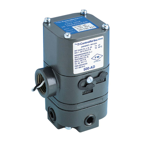
Type-595XP Explosion-proof I/P transducer, Type-330 Air Filter Regulator and gauge.
The I/PAC assembly is designed for air service only.
For individual unit specifications please see individual unit IOM (Installation, Operation and
Maintenance Instructions).
INSTALLATION
1) Mount per desired option below.
2) Connect supply air to Type-330 filter regulator.
3) Connect downstream air to I/P transducer (see unit specific IOM).
4) Connect electrical connections to I/P transducer (see unit specific IOM).
5) Set Type-330 filter regulator to desired output pressure.
6) Turn on supply air before giving units electrical signal.
MOUNTING OPTIONS
The I/PAC integrated assembly comes complete with all mounting hardware to facilitate
either direct mount onto actuator yoke or pipe mount, either direct or offset. The mounting
hardware comes labeled in individual kits for easy identification and assembly.
Mounting Kits
I/PAC Yoke Mounting Kit PN 448-542-023
I/PAC Pipe Mounting Kit PN 448-542-021
Type-595XP / Type-330
LIMITED WARRANTY & DISCLAIMER
ControlAir, Inc. products are warranted to be free from defects in materials and workmanship
for a period of one year from the date of manufacture, provided said products are used
according to ControlAir, Inc. recommended usages. ControlAir, Inc.’s liability is limited to
repair of, refund of purchase price paid for, or replacement in kind of, at ControlAir, Inc.’s
sole option, any products proved defective. ControlAir, Inc. reserves the right to discontinue
manufacture of any product or change product materials, design or specifications without
notice. Note: ControlAir does not assume responsibility for the selection, use, or
maintenance of any product. Responsibility for the proper selection, use, and maintenance of
any ControlAir product remains solely with the purchaser and end user.
Y
OKE MOUNT OR OFFSET PIPE MOUNT DIRECT PIPE MOUNT
These products are intended for use in industrial compressed air systems only.
Do not use these products where pressures and temperatures can exceed those
listed under Specifications.
Before using these products with fluids other than air, for non-industrial
applications, life-support systems, or other applications not within published
specifications, consult ControlAir, Inc.
8 Columbia Drive, Amherst, New Hampshire 03031 U.S.A.
Tel: (603) 886-9400 ♦Fax: (603) 889-1844
www.controlair.com
441-622-112 rev. 10/27/10
Installation, Operation and
Maintenance Instructions
I/PAC – Type 950XP
Integrated Process Air Control Assembly
INTRODUCTION
I/PAC (Integrated Process Air Control) – Type 950XP assembly consists of the following pre-
assembled package:
Type-950XP Explosion-proof I/P transducer, Type-330 Air Filter Regulator and gauge.
The I/PAC assembly is designed for air or gas service only.
For individual unit specifications please see individual unit IOM (Installation, Operation and
Maintenance Instructions).
INSTALLATION
1) Mount per desired option below.
2) Connect supply air to Type-330 filter regulator.
3) Connect downstream air to I/P transducer (see unit specific IOM).
4) Connect electrical connections to I/P transducer (see unit specific IOM).
5) Set Type-330 filter regulator to desired output pressure.
6) Turn on supply air before giving units electrical signal.
MOUNTING OPTIONS
The I/PAC integrated assembly comes complete with all mounting hardware to facilitate
either direct mount onto actuator yoke or pipe mount, either direct or offset. The mounting
hardware comes labeled in individual kits for easy identification and assembly.
Mounting Kits
I/PAC Yoke Mounting Kit PN 448-542-023
I/PAC Pipe Mounting Kit PN 448-542-024
Type-950XP / Type-330
LIMITED WARRANTY & DISCLAIMER
ControlAir, Inc. products are warranted to be free from defects in materials and workmanship
for a period of one year from the date of manufacture, provided said products are used
according to ControlAir, Inc. recommended usages. ControlAir, Inc.’s liability is limited to
repair of, refund of purchase price paid for, or replacement in kind of, at ControlAir, Inc.’s
sole option, any products proved defective. ControlAir, Inc. reserves the right to discontinue
manufacture of any product or change product materials, design or specifications without
notice. Note: ControlAir does not assume responsibility for the selection, use, or
maintenance of any product. Responsibility for the proper selection, use, and maintenance of
any ControlAir product remains solely with the purchaser and end user.
Y
OKE MOUNT OR OFFSET PIPE MOUNT DIRECT PIPE MOUNT
NOTE: ROTATE T330 900
These products are intended for use in industrial compressed air and gas
systems only. Do not use these products where pressures and temperatures
can exceed those listed under Specifications.
Before using these products with fluids other than air, for non-industrial
applications, life-support systems, or other applications not within published
specifications, consult ControlAir, Inc.
8 Columbia Drive, Amherst, New Hampshire 03031 U.S.A.
Tel: (603) 886-9400 ♦ Fax: (603) 889-1844
www.controlair.com
441-622-100 rev. 10/21/10
Installation, Operation and
Maintenance Instructions
TYPE 330
Pressure Re
g
ulator
16
15
14
13
12
11
9
8
7
6
5
4
3
2
1
10
INTRODUCTION
These regulators are designed for air or gas service only. Maximum allowable inlet pressure
is 250 psi. Operating temperatures are 0 to 1600F. The Type-330 has low capacity internal
relief which provides very limited downstream over pressure protection. Note: Non-relieving
version does not provide internal relief. To avoid exceeding outlet pressure limits in service,
a pressure-relieving or pressure-limiting device should be provided.
INSTALLATION
Install the regulator as close as possible to the instrument or tool it is to service. For best
filter drainage orient the drain valve so that it is at the lowest point on the dripwell housing.
The words "IN" and "OUT" are cast into the body to indicate the direction of flow.
OPERATION
Prior to turning on supply air, back off adjusting screw until there is no compression of the
range spring. After turning supply pressure on, turn the adjusting screw clockwise to
increase outlet pressure.
MAINTENANCE
1) To remove condensate, slowly open drain valve and bleed accumulated liquid.
2) To clean filter element
a. Shut off supply air
b. Drain condensate
c. Remove four corner bolts from bottom of unit
d. Remove dripwell housing and filter
e. Clean parts and reassemble in reverse order
3) To install replacement parts
a. Order kit as described in exploded view below
b. Shut off supply air. Back out adjusting screw
c. Remove four corner bolts from bottom of the unit and four screws on top and remove
all parts.
d. Replace all parts that show excessive wear
e. Clean all parts and replace in reverse order
WARNING: The materials of the Type-330 are compatible with sweet natural gas. The
user should be warned, however, that the Type-330 regulator may vent some gas to the
atmosphere. In hazardous or flammable service, vented gas may accumulate and cause
personal injury, death, or property damage due to fire or explosion. If regulator is used
in a hazardous gas service area, the regulator must be vented to a remote, safe location
away from air intakes or any other hazardous area. The vent line or stack opening must
be protected against condensation or clogging. Do not use these products where
pressures and temperatures can exceed those listed under specifications.
Parts List
ITEM QTY DESCRIPTION
1 1 Adjusting Screw
2 1 Locknut
3 4 Bonnet Build Screw
4 1 Bonnet
5 1 Spring Guide
6 1 Range Spring
7 1 Diaphragm Assembly
8 1 Body
9 1 Pintle Assembly
10 1 Pintle Spring
11 1 Filte
r
12 1 Filter Retainer Assembly
13 1 Dripwell O-ring
14 1 Dripwell
15 4 Dripwell Build Screw
16 1 Drian Valve
LIMITED WARRANTY & DISCLAIMER
ControlAir, Inc. products are warranted to be free from defects in materials and workmanship for a
period of one year from the date of manufacture, provided said products are used according to
ControlAir, Inc. recommended usages. ControlAir, Inc.’s liability is limited to repair of, refund of
purchase price paid for, or replacement in kind of, at ControlAir, Inc.’s sole option, any products
proved defective. ControlAir, Inc. reserves the right to discontinue manufacture of any product or
change product materials, design or specifications without notice. Note: ControlAir does not
assume responsibility for the selection, use, or maintenance of any product. Responsibility for the
proper selection, use, and maintenance of any ControlAir product remains solely with the
purchaser and end user.
RepairKits:PartNo.
Relieving:449‐871‐100

Other controlair Transducer manuals

controlair 2000 Manual

controlair

controlair 2000 Manual

controlair 500-BD Manual

controlair

controlair 500-BD Manual

controlair 500-AA Manual

controlair

controlair 500-AA Manual

controlair 500 Series Manual

controlair

controlair 500 Series Manual

controlair 595XP Manual

controlair

controlair 595XP Manual

controlair 550 Series Manual

controlair

controlair 550 Series Manual

controlair 500X Manual

controlair

controlair 500X Manual

Popular Transducer manuals by other brands

NK TECHNOLOGIES VTU Series instructions

NK TECHNOLOGIES

NK TECHNOLOGIES VTU Series instructions

MCM Custom Audio BT50 user manual

MCM Custom Audio

MCM Custom Audio BT50 user manual

Setra Systems AXD operating instructions

Setra Systems

Setra Systems AXD operating instructions

Simrad 50-7 - INSTALLATION REV A installation manual

Simrad

Simrad 50-7 - INSTALLATION REV A installation manual

Baumer GCA5 Assembly instruction and safety information

Baumer

Baumer GCA5 Assembly instruction and safety information

HBM C18 Mounting instructions

HBM

HBM C18 Mounting instructions

Camille Bauer SINEAX I 552 operating instructions

Camille Bauer

Camille Bauer SINEAX I 552 operating instructions

S+S Regeltechnik PREMASGARD ALD Operating Instructions, Mounting & Installation

S+S Regeltechnik

S+S Regeltechnik PREMASGARD ALD Operating Instructions, Mounting & Installation

UIS WDT-110 user manual

UIS

UIS WDT-110 user manual

Balluff BTL7 Series Condensed guide

Balluff

Balluff BTL7 Series Condensed guide

Lumel P300 User Manual & Quick Start

Lumel

Lumel P300 User Manual & Quick Start

Simrad ES120-4X10 -  REV D datasheet

Simrad

Simrad ES120-4X10 - REV D datasheet

Daiichi Electronics VETT2-91A instruction manual

Daiichi Electronics

Daiichi Electronics VETT2-91A instruction manual

Setra Systems 567 installation guide

Setra Systems

Setra Systems 567 installation guide

Rishabh RISH CON - I operating manual

Rishabh

Rishabh RISH CON - I operating manual

Siedle Novotechnik TLM Series manual

Siedle

Siedle Novotechnik TLM Series manual

LEM ITZ 10000-SB FLEX ULTRASTAB manual

LEM

LEM ITZ 10000-SB FLEX ULTRASTAB manual

MAMAC SYSTEMS EP-313 installation instructions

MAMAC SYSTEMS

MAMAC SYSTEMS EP-313 installation instructions

manuals.online logo
manuals.online logoBrands
  • About & Mission
  • Contact us
  • Privacy Policy
  • Terms and Conditions

Copyright 2025 Manuals.Online. All Rights Reserved.