BEL BM-A1 User manual

BM-A1
Audio monitor/alarm system
User’s Guide Version 0.2 05/02/04

BEL DIGITAL AUDIO BM-A1
2004 BEL (Digital Audio) Ltd
BEL (Digital Audio) Ltd. has made every effort to ensure the accuracy of information contained within
this document which is nevertheless supplied for information purposes only and does not constitute
any form of warranty or guarantee.
All trademarks acknowledged.
The information in this document is subject to change without notice.
Bel Digital Audio Ltd.
Unit 3
Horwood Court
Bletchley
Milton Keynes
Bucks
MK11RD
Tel: 01908-641063
Email: info@beldigital.com
Web: www.beldigital.com

BEL DIGITAL AUDIO BM-A1
2004 BEL (Digital Audio) Ltd
C
Co
on
nt
te
en
nt
ts
s
INTRODUCTION 1
Main features 1
OPERATION 3
SELECTING SOURCES 3
USING ALARMS 3
Alarm arming 4
BARGRAPH SCALES 5
INSTALLATION 6
CONNECTOR I/O 6
Alarms connector pinout 6
RS232 Host interface connector pinout 7
CONFIGURATION 8
Adjusting analog input level 9
Adjusting audio monitor output level 10
Adjusting bargraph break-points and ballistics 11
Inserting bargraph graticules 14
BM-A1 SERIAL PROTOCOL 15
OVERVIEW 15
Frame format 15
COMMANDS 16
DATA FORMATS 17
PROBLEM SOLVING 21
Sample problems and their solutions 22
SPECIFICATION 23

BEL DIGITAL AUDIO BM-A1 Introduction
2004 BEL (Digital Audio) Ltd 1 Version 0.2
I
In
nt
tr
ro
od
du
uc
ct
ti
io
on
n
The BM-A1 is a professional audio monitor and alarm system housed in a 1U rack.
The unit features three internal speakers, left, right and bass.
Audio input signals can be in the form of analog or AES.
The BM-A1 accepts audio inputs in groups of 4 channels from the selected source and can
direct any two from these to the speakers. The same signal is also available as a line-level
audio monitor output.
Alarms can be set to monitor audio-over-level, audio-loss and anti-phase.
Main features
•2 x AES and 2 x analog audio input pairs
•Option for balanced XLR or unbalanced BNC digital audio I/O
•High-quality, high SPL audio reproduction with bass speaker and soft limiting
•4 x tri-color bargraphs with six standard scales and ballistics, adjustable color
transition points and peak-hold facility
•Alarms for audio/AES loss, over-level and anti-phase
•Line level analog audio output of sources directed to loudspeakers
•Headphone connector with speaker mute
•Individually user-calibrated audio level inputs/outputs and metering
•Windows GUI and separate RS232 protocol for remote control of all alarm functions
and audio switching
•TTL port for alarms reset and remote alarms indication

BEL DIGITAL AUDIO BM-A1 Introduction
2004 BEL (Digital Audio) Ltd 2 Version 0.2
The BEL Digital BM-A1
All audio inputs are converted to 24 bit digital form and AES inputs are re-sampled using
sample rate converters where necessary at an internally generated 48kHz.
The audio source switch selects which audio source is available to the speaker selectors, the
bargaphs and the analogue audio monitor line-out connectors.
The left and right speaker switches select which of the currently selected audio channels is
available at the speakers after three stages of analog processing.
The selected audio is first passed through factory preset equalization filters. Then electronic
level control is applied with the balance and volume knobs providing control voltages. Soft
limiters are used to protect the speakers. The headphone output, which is taken before the
limiters, mutes the speakers when used. Alarm tone is added just before the speaker output.
When select switches are used a soft mute is applied to the audio to reduce glitches.

BEL DIGITAL AUDIO BM-A1 Operation
2004 BEL (Digital Audio) Ltd 3 Version 0.2
O
Op
pe
er
ra
at
ti
io
on
n
The front panel user interface consists of 5 rotary controls, an alarms switch, and four
bargraphs. In addition there is a headphone output, two LEDs for sustained anti-phase and a
further five LED indicators.
The BM-A1front control panel
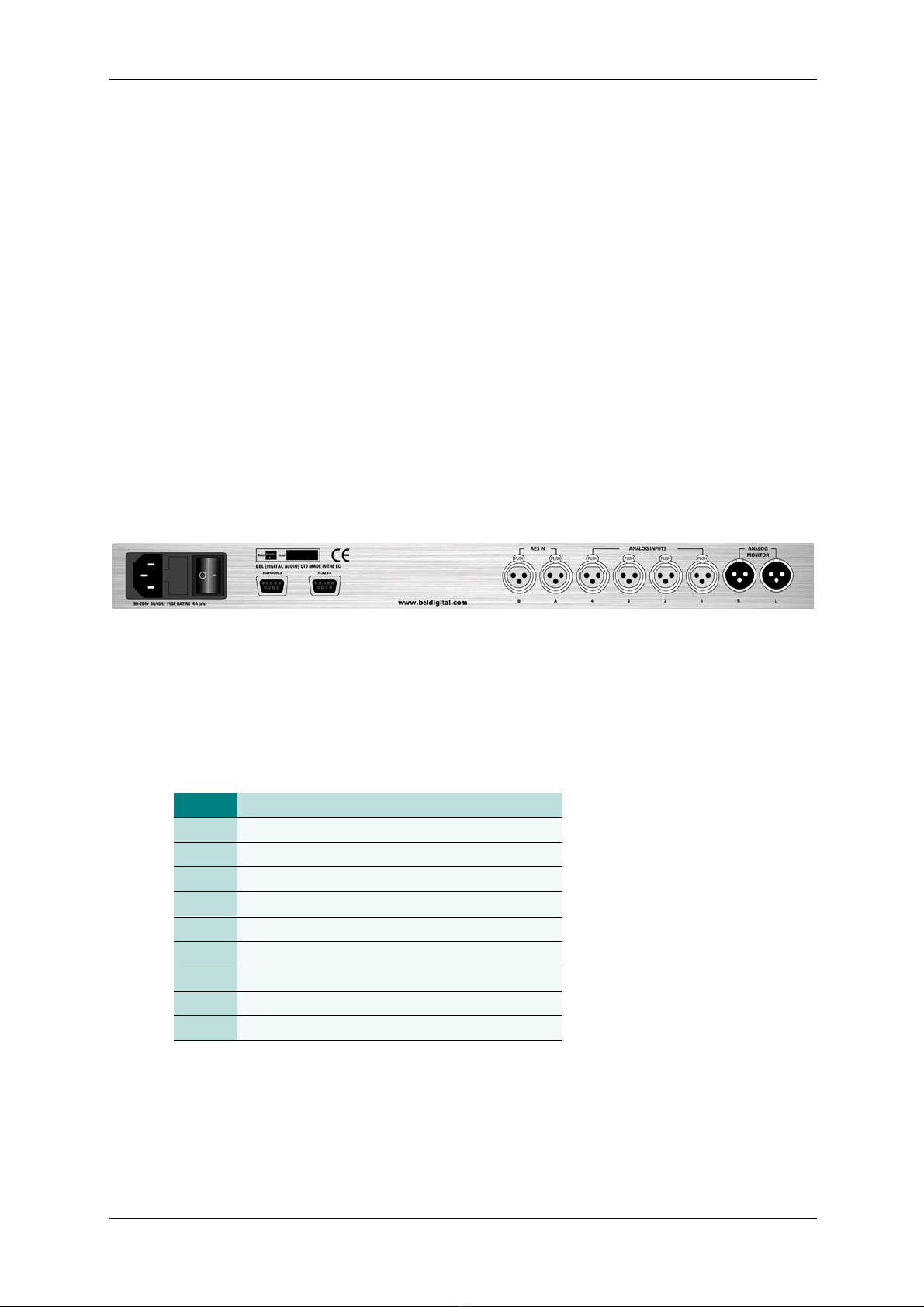
Selecting sources
The audio source switch routes either analogue or AES source audio to the speaker
selectors, the bargaphs and the monitoring line output.
Using alarms
The BM-A1 can provide the following warnings:
Alarm event Notes Alarm indication
Audio loss The currently selected four audio channels are
monitored for persistent under-level. An alarm is
generated when an input is < -30dB (-50dB for
AES meter) for more than 15 seconds.
Bottom bargraph segment
flashes amber
Audio tone, TTL/serial o/p
Audio-over-
level
The currently selected four audio channels are
monitored for transient over-level. An alarm is
generated immediately when the first red
segment of the relevant bargraph is illuminated.
Bottom bargraph segment
flashes red
Audio tone, TTL/serial o/p
Audio anti-
phase
Audio pairs 1&2 and pairs 3&4 are monitored for
sustained anti-phase.
Phase LED illuminates
Audio tone, TTL/serial o/p
(if enabled)
Note: The over-level alarm threshold can be adjusted by moving the red bar transition point.
The anti-phase tone and external alarm can only be armed via serial control.

BEL DIGITAL AUDIO BM-A1 Operation
2004 BEL (Digital Audio) Ltd 4 Version 0.2
Alarm arming
No alarms are generated unless alarm functions have been ‘armed’.
The front panel alarm toggle switch has four functions:
1. Left hand position held – ALARM RESET - any armed input alarms are cleared
2. Left hand position momentary – resets bargraph peak-level indicators
3. Middle position – OFF/MUTE - the internal audible alarm is muted
4. Right hand position – SET - alarm functions are selectively armed
The switch must be held in the left hand ALARM RESET position for more than 3 seconds for
a reset to occur.
In the right hand SET position the inputs currently active are automatically detected and the
appropriate alarms are selectively enabled. The unit is then set to monitor only the active
inputs. The SET function can be disabled using a serial command.
If alarms are present, moving the toggle switch to the center position will stop the audible
alarm, but retain the visual alarm indications and TTL/serial alarm outputs. The switch must
be held in the ALARM RESET position for more than 3 seconds for all alarms to be cleared.
The center position is the recommended position when alarm indication is not required.
Note: Restoring input signals to normal condition does not clear alarms.
Arming phase alarms
Only the phase LED on the front panel is armed using the SET switch. The audio tone and
external phase alarms can only be armed using serial control.
To prevent the anti-phase detector from generating intermittent alarms, only persistent anti-
phase conditions are used to raise an external alarm or generate an audio tone.
An alarm is generated when an anti-phase condition exists for more than 10 seconds.

BEL DIGITAL AUDIO BM-A1 Operation
2004 BEL (Digital Audio) Ltd 5 Version 0.2
Bargraph scales
The following bargraph ballistics may be selected using internal switches.
Scale type Range Attack Fallback
AES/EBU: 60dB (0 to -60dB) 1ms 1.5Sec per 20dB decay
DIN PPM: 55dB (+5 to -50dB) 10mSec 1.5Sec per 20dB decay
VU: 23dB (+3 to -20dB) 300mSec 300mSec
BBC PPM: +12 to-12dB - mark 7 to 1 10mSec 2.85Sec - mark 7 to 1
VU EXT: 80dB (+20 to -60dB) 300mSec 300mSec
NORDIC: 54dB (+12 to -42dB) 5mSec 1.7Sec per 20dB decay
BM-A1 scale ballistics
Stick-on scale graticules, which may be applied to the space between the front-panel
bargraphs, are supplied with the unit.
BM-A1 scale graticules
Note: Bargraph color transition points and peak hold decay may also be adjusted
internally.
Refer to the Configuration chapter for switch settings and graticule fitting
instructions.

BEL DIGITAL AUDIO BM-A1 Installation
2004 BEL (Digital Audio) Ltd 6 Version 0.2
I
In
ns
st
ta
al
ll
la
at
ti
io
on
n
The BM-A1 1U frame may be installed in 19 inch bays with 327mm depth including typical
cable and connector depth. The dimensions of the BM-A1 are 483x283x44.3. Its weight is
5kg and the max power dissipated is 60 W.
Ventilation is by natural convection and there are vents at each side and on the top and
bottom covers of the unit. Frames may be installed into bays, providing airflow through these
vents is not impeded.
Connector I/O
All connections, with the exception of the headphone socket, are provided on the rear panel
of the frame. All data connectors use 9 way ‘D’ type connectors.
The BM-A1balanced audio version rear view
Digital audio I/O may be supported with either XLR connectors for balanced audio or BNCs
for unbalanced audio, depending on the BM-A1version specified at the time of ordering.
Alarms connector pinout
Connector type: 9 way sub-D female
Pin Description
1Audio alarm out (TTL compatible active high)
2Not used
3Reset in (TTL compatible active low)
4GND
5Not connected
6Not connected
7Not connected
8Not connected
9Not connected
Note: TTL outputs can supply up to 10mA.

BEL DIGITAL AUDIO BM-A1 Installation
2004 BEL (Digital Audio) Ltd 7 Version 0.2
RS232 Host interface connector pinout
Connector type: 9 way D female
Speed: 9600 bps
Format: 8 bit, no parity, 2 stop bits
Pin Description
1Not connected
2Rx (from host)
3Tx (to host)
4Not connected
5GND
6Not connected
7Not connected
8Not connected
9Not connected
Note: A null-modem lead will be required to interface to a PC.

BEL DIGITAL AUDIO BM-A1 Configuration
2004 BEL (Digital Audio) Ltd 8 Version 0.2
C
Co
on
nf
fi
ig
gu
ur
ra
at
ti
io
on
n
Access to BM-A1internal adjustments is obtained with the top removed.
BM-A1 internal adjustments
The following adjustments may be made:
•Monitor output level – SW3 & potentiometers main board RV1 & RV2
•Analog input level – SW4 and SW5 & potentiometers RV3/4/5/6 main board
•Bargraph settings – SW2 and SW6 main board, near power supply
Warning: Configuration instructions are for trained personnel. To avoid dangerous electric
shock, do not remove any covers or carry out adjustments unless qualified to do so.

BEL DIGITAL AUDIO BM-A1 Configuration
2004 BEL (Digital Audio) Ltd 9 Version 0.2
Adjusting analog input level
In the following tables, ON is obtained with a switch lever in the DOWN position. The
adjustments are located on the main board under the output sub-board.
Analog input adjustments – 0dB setting shown
SW4 Anlg
Input
Setting when ON
110 dB (0dBu in = 0 on analog scale)
214 dB (+4dBu in = 0 on analog scale)
318 dB (+8dBu in = 0 on analog scale)
41Variable – adjacent pot* –10 to +12 dB
520 dB (0dBu in = 0 on analog scale)
624 dB (+4dBu in = 0 on analog scale)
728 dB (+8dBu in = 0 on analog scale)
82Variable – adjacent pot* –10 to +12 dB
SW5 Anlg
Input
Setting when ON
130 dB (0dBu in = 0 on analog scale)
234 dB (+4dBu in = 0 on analog scale)
338 dB (+8dBu in = 0 on analog scale)
43Variable – adjacent pot* –10 to +12 dB
540 dB (0dBu in = 0 on analog scale)
644 dB (+4dBu in = 0 on analog scale)
748 dB (+8dBu in = 0 on analog scale)
84Variable – adjacent pot* -10 to +12 dB
Note: It is intended that only one switch lever is set ON for each analog input.
The ON position is obtained with a switch lever in the direction of the arrow
(downward in the above drawing).
*Clockwise rotation increases gain.

BEL DIGITAL AUDIO BM-A1 Configuration
2004 BEL (Digital Audio) Ltd 10 Version 0.2
Adjusting audio monitor output level
In the following tables, ON is obtained with a switch lever in the DOWN position. The
adjustments are located on the main board under the output sub-board.
Analog monitor output adjustments – 0dB setting shown
SW3 Monitor
Output
Setting when ON
1Left 0 dB (0 on analog scale = 0dBu on output)
2Left 4 dB (0 on analog scale = +4dBu on output)
3Left 8 dB(0 on analog scale = +8dBu on output)
4Left Variable – adjacent pot* 0 to +12 dB
5Right 0 dB (0 on analog scale = 0dBu on output)
6Right 4 dB (0 on analog scale = +4dBu on output)
7Right 8 dB(0 on analog scale = +8dBu on output)
8Right Variable – adjacent pot* 0 to +12 dB
Note: It is intended that only one switch lever is set to ON for each monitor output.
The ON position is obtained with a switch lever in the direction of the arrow
(downward in the above drawing).
*Clockwise rotation increases gain.

BEL DIGITAL AUDIO BM-A1 Configuration
2004 BEL (Digital Audio) Ltd 11 Version 0.2
Adjusting bargraph break-points and ballistics
The adjustments, SW2 and SW6 are located near the power supply.
BM-A1bargraph adjustments
SW2-8 AES to analog adjust
OFF
ON
-18dBFS = 0 on analog scale
-20dBFS = 0 on analog scale
The –18dB and –20dB settings define the correspondence between AES input level and the
0 mark on an analog scale. This allows analog scales to be used with digital signals.
Note: When digital inputs are used with an analogue scale the analogue outputs will be less
than that indicated on the meters since the digital to analogue converters clip at +15
dB. The effective loss is -3dB when the 18 dB position is selected and -5dB when the
20 dB position is selected.
SW2-7 SW2-6 Peak hold decay
OFF OFF None (Off)
OFF ON 3 seconds
ON OFF 7 seconds
ON ON Indefinite
SW2-5 SW2-4 SW2-3 Scale type
OFF OFF OFF AES
OFF OFF ON DIN
OFF ON OFF VU
OFF ON ON BBC
ON OFF OFF Extended VU
ON OFF ON NORDIC
ON ON OFF No scale
ON ON ON No scale
Note: The OFF position is obtained with a switch lever in the direction of the arrow, (to the
right in the above drawing).

BEL DIGITAL AUDIO BM-A1 Configuration
2004 BEL (Digital Audio) Ltd 12 Version 0.2
The bargraph displays have 26 LEDs. The bottom LED in each bar is reserved for the audio
under and over level alarm. The remaining 25 LED level segments may be assigned to three
colored zones, red, amber and green.
Up to 25 of the top most segments may be colored red. Up to 25 segments from the end of
the red zone downward may be colored amber and the remaining segments (if any) are
always green.
Choosing how many segments are colored red from the top of the bargraph sets the ‘red
zone’. Select from none to 25 using SW2-2, SW2-1, SW6-8, SW6-7 and SW6-6 as follows:
SW2-2 SW2-1 SW6-8 SW6-7 SW6-6 Segment from bargraph top
OFF OFF OFF OFF OFF None
OFF OFF OFF OFF ON 1
OFF OFF OFF ON OFF 2
OFF OFF OFF ON ON 3
OFF OFF ON OFF OFF 4
OFF OFF ON OFF ON 5
OFF OFF ON ON OFF 6
OFF OFF ON ON ON 7
OFF ON OFF OFF OFF 8
OFF ON OFF OFF ON 9
OFF ON OFF ON OFF 10
OFF ON OFF ON ON 11
OFF ON ON OFF OFF 12
OFF ON ON OFF ON 13
OFF ON ON ON OFF 14
OFF ON ON ON ON 15
ON OFF OFF OFF OFF 16
ON OFF OFF OFF ON 17
ON OFF OFF ON OFF 18
ON OFF OFF ON ON 19
ON OFF ON OFF OFF 20
ON OFF ON OFF ON 21
ON OFF ON ON OFF 22
ON OFF ON ON ON 23
ON ON OFF OFF OFF 24
ON ON OFF OFF ON 25
ON ON OFF ON OFF 25
ON ON OFF ON ON 25
ON ON ON OFF OFF 25
ON ON ON OFF ON 25
ON ON ON ON OFF 25
ON ON ON ON ON 25
Note: It is not possible to set 25 red and 25 amber segments, since there are only 25
segments for level display purposes.

BEL DIGITAL AUDIO BM-A1 Configuration
2004 BEL (Digital Audio) Ltd 13 Version 0.2
Choosing how many segments are colored amber from the end of ‘red zone’ sets the ‘amber
zone’. Select from none to 25 using SW6-5, SW6-4, SW6-3, SW6-2 and SW6-1 as follows:
SW6-5 SW6-4 SW6-3 SW6-2 SW6-1 Segment from last RED ZONE
OFF OFF OFF OFF OFF None
OFF OFF OFF OFF ON 1
OFF OFF OFF ON OFF 2
OFF OFF OFF ON ON 3
OFF OFF ON OFF OFF 4
OFF OFF ON OFF ON 5
OFF OFF ON ON OFF 6
OFF OFF ON ON ON 7
OFF ON OFF OFF OFF 8
OFF ON OFF OFF ON 9
OFF ON OFF ON OFF 10
OFF ON OFF ON ON 11
OFF ON ON OFF OFF 12
OFF ON ON OFF ON 13
OFF ON ON ON OFF 14
OFF ON ON ON ON 15
ON OFF OFF OFF OFF 16
ON OFF OFF OFF ON 17
ON OFF OFF ON OFF 18
ON OFF OFF ON ON 19
ON OFF ON OFF OFF 20
ON OFF ON OFF ON 21
ON OFF ON ON OFF 22
ON OFF ON ON ON 23
ON ON OFF OFF OFF 24
ON ON OFF OFF ON 25
ON ON OFF ON OFF 25
ON ON OFF ON ON 25
ON ON ON OFF OFF 25
ON ON ON OFF ON 25
ON ON ON ON OFF 25
ON ON ON ON ON 25
Note: Any remaining unassigned segments will be green.

BEL DIGITAL AUDIO BM-A1 Configuration
2004 BEL (Digital Audio) Ltd 14 Version 0.2
Inserting bargraph graticules
The following bargraph scale graticules are supplied with each BM-A1:
BM-A1 scale graticules
To apply a graticule proceed as follows:
•peel back the protective backing from the chosen graticule
•apply the graticule to the space between a pair of bargraphs
•repeat the process for the other bargraph graticule position
•ensure that the bargraph setting matches the graticule
•adjust the color transitions and peak hold decay as desired

BEL DIGITAL AUDIO BM-A1 BM-A1 serial protocol
2004 BEL (Digital Audio) Ltd 15 Version 0.2
B
BM
M-
-A
A1
1
s
se
eri
ia
al
l
p
pr
ro
ot
to
oc
co
ol
l
Overview
The BM-A1 is automatically placed in the remote mode upon receipt of a valid RS232
command. The front panel can be reactivated by powering off and on or by sending it a
disconnect command.
Commands to be communicated to the remote unit (BM-A1) are arranged in frames. These
frames will then be sent to the remote unit, which will always reply with either ACK for
acceptance or NAK for rejection. Any requested reply then follows in the same frame format.
Frame format
The frame starts with a start character 0xAA (alternating ones and zeros). This is followed by
the destination address, the source address, the command code, the data count, the data, a
checksum and an end flag 0xFE.
Start Flag 0XAA
Destination Address
Source Address
Command
Data Count
Data
Checksum
End Flag 0XFE
Start Flag:
The start flag 0XAA may be sent at any time. If sent during a frame this will cause the frame
to effectively restart.
Destination Address:
This should be set to 1.
Source Address:
This should be set to 1.
Command:
This character is the command for the remote unit and must fall in the range 0X80 to 0XEF.
More details of the relevant codes are shown below.

BEL DIGITAL AUDIO BM-A1 BM-A1 serial protocol
2004 BEL (Digital Audio) Ltd 16 Version 0.2
Data count:
This is the total number of data bytes following, up to a maximum of 127.
Data:
The data required for the command is carried here. Each character can have a value of 0X00
to 0X7F i.e. 7 bits.
Checksum:
This is the modulo sum of the characters in the frame between the destination address and
the last data character inclusively. It is calculated thus:
DO
{
checksum = (character+checksum) AND 0x7F
}
FOR ALL CHARACTERS IN FRAME.
End Flag:
A character 0XFE ends the frame.
Commands
Commands from the remote controller to the BM-A1.
Code(Hex) Function Reply
80 General prompt for a reply C0 - ACK (OK)
C1 - NAK (send again)
81 Use first data char as a second command ACK
82 Request unit identifier C2.
83 Set up switches Data count =5 See below for format ACK
84 Set up alarm functions Data count=2 See below for format ACK
85 Request Detail C5
86 Request Switches C6
Replies
Replies, when requested (e.g. 82), will consist of frames that contain the original command
value plus 0X40. So a request for an ident, 0x82, will elicit a reply of a frame containing 0xC2
and the ident string. (BM-A1Vn.n)

BEL DIGITAL AUDIO BM-A1 BM-A1 serial protocol
2004 BEL (Digital Audio) Ltd 17 Version 0.2
Data formats
General Prompt (0x80)
This command will cause the BM-A1 to respond with an ACK or NACK reply. It can be used
to poll for alarms.
Set up switches (0x83)
Bit 7 Bit 6 Bit 5 Bit 4 Bit 3 Bit 2 Bit 1 Bit 0
Byte 0 Ms bit of
Audio
select
Audio
select
Audio
select
Byte 1 Ms bit of
Right
speaker
select
Right
speaker
select
Ms bit of
Left
speaker
select
Left
speaker
select
Byte 2 Ms Red
zone
Red zone Red zone Red zone Red zone
Byte 3 Ms
amber
zone
Amber
zone
Amber
zone
Amber
zone
Amber
zone
Byte 4 AES
offset
Ms Peak
type
Peak
type
Ms bar
type
Bar type Bar type
Audio select codes
Code Function Notes
000 Analog audio input selected
001 AES audio input selected
010 None
011 None
100 None
101 None
Left and right speaker select codes
Code Function
00 Select audio input 1
01 Select audio input 2
10 Select audio input 3
11 Select audio input 4
Table of contents