manuals.online logo
Brands
  1. Home
  2. •
  3. Brands
  4. •
  5. Sony
  6. •
  7. Security System
  8. •
  9. Sony DVP-NW50 - In-wall Dvd Player User guide

Sony DVP-NW50 - In-wall Dvd Player User guide

2-584-980-11(2)
Installer’s manual
© 2005 Sony Corporation Printed in Korea
Connect ing a com put er
Connect each Unit and a computer using an Ethernet cable
(100Base-TX, optional.) For details on the connection, refer to
“Hooking up the sysytem” on this manual and the instruction
manual supplied with your router or hub.
Connect ing a TV (DVP-NW50 only)
Connections between the Unit and each of devices are made via
cables or cords coming through the wall.
Connect the Unit to a TV or a projector using the VIDEO cord.
Select one of the ways of connection methods shown below,
according to the input jack on your TV.
Precaut ions
Caution
Unauthorized substitutions may result in fire, electric shock,
causing die or serious injury.
Keep the following precautions in mind to prevent any accidents.
• Installment and settings other than that of specified
instructions may cause the unit to fall due to lack of strength of
the wall.
• Do not use screws other than the supplied screws for
installation.
• Do not install the unit following any procedure other than that
explained in this manual. Make sure to follow the procedure in
this manual closely.
• Do not disassemble the unit. This may cause a malfunction of
the unit or cause injury to you.
• Do not apply strong pressure on the unit after mounting it. The
unit may be damaged or fall, causing a injury to you.
On power sources
• The Unit is not disconnected from the AC power source as long
as it is connected to the wall outlet, even if the player itself has
been turned off.
• If you are not going to use the Unit for a long time, be sure to
disconnect the Unit from the wall outlet. To disconnect the AC
power cord, grasp the plug itself; never pull the cord.
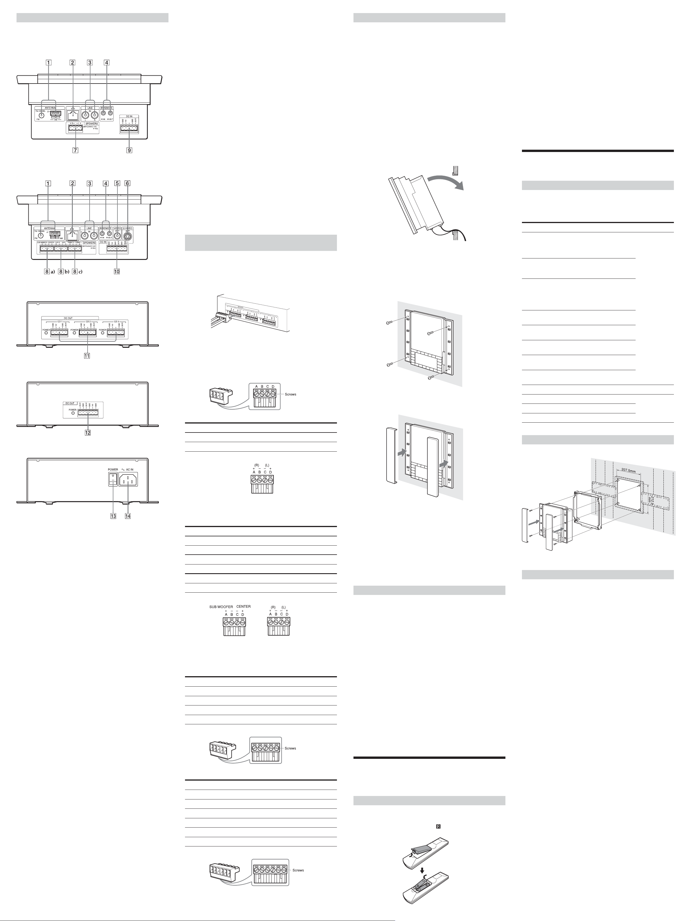
Unpacking
Item CDP-NW10 DVP-NW50
CDP-NW10 Unit 1 –
DVP-NW50 Unit – 1
Remote commander (remote) 1 1
(RM-ANU001 )
Wall mounting bracket 1 1
Wall stopper 4 4
TEMPLATE 1 1
Plug-in 4P terminal (for speakers) 1 3
Plug-in 5P terminal 1 –
(for AC power unit)
Plug-in 6P terminal – 1
(for AC power unit)
Screws for fixing the Unit to 4 4
the wall mounting bracket (short)
Screws for wall stopper (long) 4 4
AM loop antenna (aerial) 1 1
R6 (size-AA) battery 2 2
User’s manual 1 1
Installer’s manual (this manual) 1 1
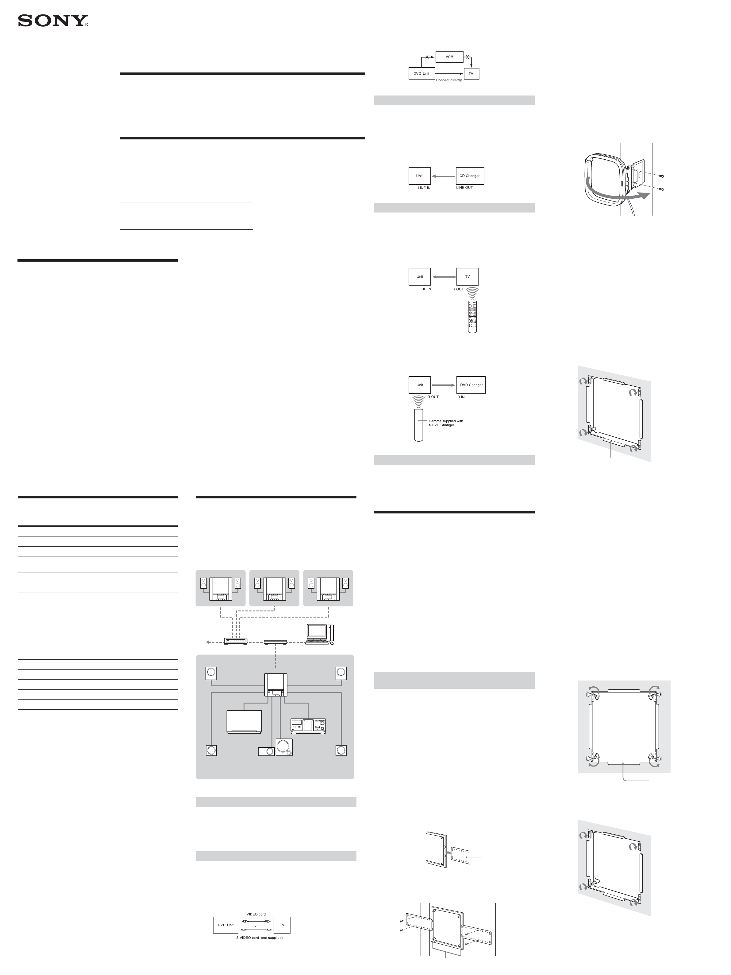
CDP-NW10/DVP-NW50 Syst em
Netw ork
The diagram below illustrates an entire system network made up
with multiple Units.
Note
The configuration shown below is for illustrative purpose only. It differs
from an actual system network.
Custom Integrated
AV System
On placement
• The Unit is designed for mounting only on the wall. You cannot
mount it on the ceiling or on the floor.
• Place the Unit in a location with adequate ventilation to
prevent heat build-up in the Unit.
• Do not place the Unit on a soft surface such as a rug.
• Do not place the Unit in a location near heat sources, or in a
place subject to direct sunlight, excessive dust, or mechanical
shock.
• Do not install the Unit in an inclined position. It is designed to
be operated in a horizontal position only.
• Keep the Unit and the discs away from equipment with strong
magnets, such as microwave ovens, or large loudspeakers.
• Do not install the unit in a humid location, such as in a
bathroom, or a place where moisture condensation may occur.
Install the Unit in a place where the environment falls within
the operating temperature 0˚C – 40˚C (32˚F – 104˚F).
• Do not step on or place heavy objects on the unit. The unit may
be damaged or fall, causing injury to you.
KITCHEN
CDP-NW10
GUEST ROOMBEDROOM
CDP-NW10CDP-NW10
Computer
Hub
Router
INTERNET
CD ChangerTV/ Project or
Front
Speaker
Front
Speaker DVP-NW50
Rear
Speaker
LIVING ROOM
Sub Woofer
Center
Speaker
Rear
Speaker
Example of the DVP-NW50 syst em netw ork
Note
Do not connect a VCR, etc., between your TV and the player. If you pass
the player signals via the VCR, you may not receive a clear image on the
TV screen. If your TV has only one video input jack, connect the Unit to
this jack.
Connect ing audio Equipm ent
Connections between the Unit and each of devices are made via
cables or cords coming through the wall.
The Unit can input sound from external audio equipment via the
audio connectors on the Unit. Connect the OUTPUT jacks (L/R)
of the audio equipment to the LINE IN (L/R) jacks of the Unit
using the proper audio cords (optional).
Connect ing an IR IN/OUT
Connections between the Unit and each of devices are made via
cables or cords coming through the wall.
You can operate a component using the remote if the IR IN/OUT
terminal of the Unit and the component are connected. For
example, if you connect IR IN of the Unit and IR OUT of a TV,
you can operate the Unit with the remote by aiming it at the TV.
If you connect IR OUT of the Unit and IR IN of a component,
such as a DVD Changer, you can operate the DVD Changer with
the remote (supplied with the DVD Changer) by aiming it at the
Unit.
Connect ing an AC pow er unit
After connecting the Unit and the AC power unit using the
power supply cables, connect the AC power cord to the AC IN of
the AC power unit, then the other end of the AC power cord to
the wall outlet.
Installing t he Unit
Before installing the Unit into the wall, take steps to ensure your
safety and that of your surroundings, then check the following:
• The location of the power source to make sure that power supply cable
can reach from the Unit.
• The location of the speakers to make sure that speaker cords can be run
between the Unit and the speakers.
• The distance between the Unit and the AC power unit (up to 200 feet
(60 m)).
• The durability of the wall (The thickness of the wall must be between
1/2 to 3/4 inches. (13 mm to 19 mm)).
• There are no obstructions, such as an air, an electrical, or a water
conduit near the location where the Unit is installed.
• There is enough space (over 6 inches (15 cm)) inside the wall. If the
space available inside the wall is insufficient or does not have proper
ventilation, a malfunction of the Unit may occur due to heat build-up.
• Do not install the Unit where the Unit may get wet due to water or
other liquid. This may cause a malfunction of the Unit.
• Do not install the Unit in a place where moisture condensation may
cause a malfunction of the Unit.
Installing bracket s for new construct ion (before
w all const ruction is finished)
You may install a pre-construction bracket on the studs where the
unit will be installed. It is recommended that you use a pre-
construction bracket when you install the unit in a house that is
still under construction. However, the pre-construction bracket is
only for the use of sub installation. You may not be able to use the
pre-construction bracket on the place where the wall and material
of the wall and pillar may be damaged or some other problems
may occur.
Note
The following items are included in the Pre-construction bracket kit (WS-
BKT1).
• Pre-construction bracket (1)
• Wings (2)
• AM Antenna (1)
• Screws for the AM Antenna (2)
• Manual (1)
1Insert the tw o w ings into the tabs of the pre-construction
bracket.
2Place the pre-construction bracket on the studs, and then
fasten the screw s (not supplied) to attach the pre-
construction bracket.
Wing
Tip
Run the cables into the hole marked with an “*” in the illustration
above, so that you can bundle and fix the cables.
Notes
• Make sure that the pre-construction bracket is properly level, both
horizontally and vertically. Improper positioning may cause the
unit to fall, or may cause difficulty when you install the Unit.
• Make sure that more than 4 inches (10 cm) of space is available
behind the wall for installing the unit.
3Place the AM loop antenna on the stud, and then fasten
the supplied screw s to attach it. Raise the entire AM
antenna, and then insert its tab into the notch to set up
the AM loop antenna.
Take care to attach the AM loop antenna on the stud as far
away from the CDP-NW10, DVP-NW50, or other electrical
devices as possible (at least 1 foot (30 cm)).
4After the w all construction is finished, cut the outline
along the inside edge of the pre-construction bracket.
Do not cut over or beyond the edge.
Before proceeding to step 4, make sure that all the necessary
cables can be run to the bracket location.
Note
Make sure that the size of the hole cut in the wall corresponds to the
specified size (height: 83/8 X 87/16 inches, 212.5 - 215 mm), (width:
83/16 X 81/4 inches, 207.5 - 210 mm). If the hole is too big to mount
the bracket, the Unit may fall and cause an accident.
5Place the mounting bracket over the hole so that the pre-
construction bracket and the mounting bracket match
across the w all. Then fasten the w all mounting bracket
screw s carefully to fix the mounting bracket and pre-
construction bracket so that they are level and align
perfectly.
Make sure the larger tab is mounted at the bottom.
Notes
• Fasten the screws securely. Failure to fasten the screws or
incomplete tightening of the screws may cause the Unit to fall and
cause an accident.
• For mounting the bracket, use the supplied screws.
To mount t he unit on the finished w all
1M ark the location w here the Unit is to be installed on the
w all using the supplied TEM PLATE (83/8 X 81/4 inches (212.5
mm X 207.5 mm)).
Make sure the mark is properly level, horizontally and
vertically.
2Cut the outline along the mark, then carefully cut a clean
hole through the w all.
Notes
• Do not cut over or beyond the outline.
• Make sure that the size if the hole cut in the wall corresponds to the
specified size. If the hole is too big to mount the bracket, the Unit
may fall and cause an accident.
• Do not make a gap between the wall and the mounting bracket.
3Rotate the stoppers to the inside of the frame, and then
place the mounting bracket over the hole.
Make sure the larger tab is mounted at the bottom.
4Rotate the stoppers to the outside of the frame behind
the w all.
5Fasten the w all mounting bracket screw s carefully so that
the w all mounting bracket is level.
Notes
• Fasten the screws securely. Failure to fasten the screws or
incomplete tightening of the screws may cause the Unit to fall and
cause an accident.
• For mounting the bracket, use the supplied screws.
Larger tab
Larger tab
*
This manual is for installers only.
Contact your nearest installer for details on making
the required connections for the system network.
Downloaded from: https://www.usersmanualguide.com/
Speaker hookup
Before connecting each of speaker cables to the Unit, you must
connect them to the supplied speaker connector. See
“Connecting speaker cables to the speaker connector.”
7SPEAKERS (CDP-NW10)
Connects speakers in a room using a speaker cable.
8SPEAKERS (DVP-NW50)
a) SUB W OOFER/ CENTER
Connects a sub woofer and a center speaker using a speaker
cable .
b) SUR R/ SUR L
Connects surround speakers using speaker cables.
c) FRONT R/ FRONT L
Connects front speakers using speaker cables.
Other hookup
9DC IN for the CDP-NW10/
0DC IN for the DVP-NW50
Connects the DC IN connector using the power supply cables
inserted to connect the AC power unit and a Unit.
qa DC OUT for the CDP-NW10/
qs DC OUT for the DVP-NW50
Connects the DC OUT connector using the power supply cables
inserted to connect the AC power unit and a Unit.
qd POWER
Turns the AC power units on.
qf AC IN
Plugs the AC power cord to the AC IN of the AC power unit.
Connect ing speaker cables or pow er supply
cables t o t he connectors
You must connect the speaker cables from each of the speakers to
the proper speaker connector, then plug it into the SPEAKER
OUT terminal of the Unit. Also you must connect the power
supply cables to the DC IN connector, then plug it into the DC
OUT terminal of the AC power unit.
Speaker connect or f or CDP-NW10/DVP-NW50
Be sure to match the speaker cables to the appropriate terminal
on the connector: + to + and – to –. If a cable is reversed, the
sound may be distorted. Use an ordinary screwdriver to fasten
the screws.
CDP-NW10
Connect the To the Then, to the SPEAKER OUT
Speaker + (R)/ – (R) A/B7
Speaker + (L)/– (L) C/D7
DVP-NW50
Three speaker connectors are required for the DVP-NW50 since it
produces 5.1ch surround sound.
Connect the To the Then, to the SPEAKER OUT
Sub woofer +/Sub woofer – A/B8a)
Center speaker + / – C/D8a)
Surround speaker + (R)/ – (R) A/B8b)
Surround speaker + (L)/– (L) C/D8b)
Front speaker + (R)/ – (R) A/B8c)
Front speaker + (L)/– (L) C/D8c)
DC IN connect or for the CDP-NW10/DVP-NW50
Use Sony’s connecting cables for the required connections of the
Unit and AC power unit.
CDP-NW10
Connect the (cable color) To the Then, to the DC IN/OUT
GND Black A9/ qa
14V Yellow B9/ qa
GND Blue C9/ qa
29.5V Red D9/ qa
ABCD
DVP-NW50
Connect the (cable color) To the Then, to the DC IN/OUT
GND Black a0/ qs
14V Yellow b0/ qs
GND Brown c0/ qs
ND Orange d0/ qs
16V Blue e0/ qs
29.5 Red f0/ qs
abcdef
M ounting t he Unit into t he w all
Before connecting the cords and cables, make sure of the
following:
• Cords and cables to be connected to the Unit reach to the Unit
location.
• Turn off all of the components before making any connections.
• Do not connect the AC power cords until all of the connections
are completed.
• Be sure to make connections firmly to avoid hum and noise.
1Connect each of the cords and cables to the corresponding
connectors.
See “Hooking up the system” for details on the connections.
Make sure each of the cords and cables is connected securely.
2When you have finished making all of the connections,
insert the bottom of the Unit onto the mounting bracket
first, then push the top of the Unit onto the bracket.
If the Unit does not slide into the mounting bracket, remove
the Unit from the bracket, then loosen or fasten the screws to
adjust the mounting bracket position.
Note
It is recommended that you test the system connection before
proceeding to step 3.
3Fix the Unit onto the w all w ith the screw s at the four
points as show n below.
4Press the side panels in at both sides of the Unit until they
click.
To uninst all the Unit
1Turn off the AC pow er unit, then disconnect the AC power
cord from t he w all out let .
2Perform steps f rom 4 to 1 in “ Mounting the Unit into t he
wall.”
3Remove all the cables and t he cords f rom the Unit and the
AC power unit .
4Remove t he mounting bracket from the pre-construct ion
bracket or the wall.
Connect ing the AC pow er Unit
You can connect up to four Units (CDP-NW10), or one Unit
(DVP-NW50) to an AC power unit.
Before connecting the AC power cord of the AC power unit to a
wall outlet, connect all parts of the system to the Unit.
Note
After completing all the connections, make sure there are no mis-
connections or improper wiring before plugging the Unit into the
wall outlet. Improper wiring or mis-connections may cause the
Unit to be damaged.
1M ake sure all the pow er supply cables are inserted into
the proper DC IN/ OUT connector.
2Plug the DC IN/ OUT connector into the DC OUT of the AC
pow er unit w ith the screw side facing up.
3Plug the AC pow er cord into AC IN of the AC pow er Unit.
4Plug the other end of the AC pow er cord into the w all
outlet.
5When you have completed all the required settings, turn
on the AC pow er unit.
Set ting up the Units
Preparing t he remote
Insert two R06 (size-AA) batteries into the battery compartment
with the + and – correctly oriented to the markings. When using
the remote, point it at the IR sensor on the Unit.
Notes
• Under normal conditions, the batteries should last for about six months.
When the remote no longer operates the player, replace both batteries
with new ones.
• Do not leave the remote in an extremely hot or a humid place.
• Do not drop any foreign object into the remote casing, particularly
when replacing the batteries.
• Do not use a new battery with an old one.
• Do not expose the IR sensor to direct sunlight or lighting equipment.
Doing so may cause a malfunction.
• If you do not intend to use the remote for an extended period of time,
remove the batteries to avoid possible damage from battery leakage and
corrosion.
You must also customize the following settings. Refer to the
“Setting up the Units” in Chapter 1 of the User’s Manual.
• IP address
• Naming the Unit.
• Setting the time
Ref erence
Default value of the User set up M enu
The table shown below describes the default setting of items on
the User setup Menu. To change these items, refer to each chapter
in the User’s manual indicated below.
Item Default value Chapter No.
SP.SIZE FRONT Chapter 8
(speaker size) CENTER
SURROUND
S.WOOFER
SP.DISTANCE FRONT 10 ft (3m)
(speaker distance) CENTER 10 ft (3m)
SURROUND 10 ft (3m)
LEVEL (DVD-NW50 only)
S.WOOFER 0 dB
FRONT 0 dB
CENTER 0 dB
SURROUND L 0 dB
SURROUND R 0 dB
DIMMER OFF
(CVD-NW10 only)
DRC OFF
(DVD-NW50 only)
TEST TONE OFF
(DVD-NW50 only)
VOL.PRESET OFF
(volume preset)
VOL.LEVEL OFF
(volume level)
IR ROUTE Both Chapter 1
INTERCOM PRIVACY OFF Chapter 6
MONITOR PRIVACY OFF
PARTY PRIVACY OFF
Dim ensions
Specifications
Pow er requirement s: AC 120 V, 60 Hz
DC Pow er consumption:
CDP-NW10: DC 29.5 V/1 A, DC 14 V/1.5 A
DVP-NW50: DC 29.5 V/1 A, DC 29.5 V/1 A,
DC 14 V/1.5 A
AC Pow er consumpt ion:
AC-NW10: AC 120 V/3.6 A
AC-NW50: AC 120 V/2.1 A
DC out put : AC-NW10: DC 29.5 V, DC 14 V for output 1
DC 29.5 V, DC 14 V for output 2
DC 29.5 V, DC 14 V for output 3
AC-NW50: DC 29.5 V for output 1
DC 29.5 V for output 2
DC 14 V for output 3
Operat ing t emperat ure:
0˚C – 40˚C (32˚F – 104˚F)
Storage t emperat ure:
-20˚C – 60˚C (-4˚F – 140˚F)
Dimensions: CDP-NW10/DVP-NW50:
230 ✕266 ✕104 mm
(9 1/8✕10 1/2✕4 1/8inches)
AC-NW10/NW50:
244 ✕316 ✕72 mm
(9 5/8✕12 1/2✕2 7/8inches)
Mass: CDP-NW10: 2.5 kg (5 lbs 8 oz.)
DVP-NW50: 2.7 kg (5 lbs 15 oz.)
AC-NW10: 2.7 kg (without AC code)
AC-NW50: 2.5 kg (without AC code)
Design and specifications are subject to change without notice.
Hooking up the system
An optional AC power unit (AC-NW10/AC-NW50) is required
to hook up the system.
CDP-NW10
DVP-NW50
AC-NW10 AC power unit for CDP-NW10 (front) (optional)
AC-NW50 AC power unit for DVP-NW50 (front) (optional)
AC-NW10/AC-NW50 (rear) (optional)
Antenna hookup
You can tune in AM/FM stations using the Unit.
1ANTENNA (AM / FM )
Connects the AM loop antenna to the AM terminal.
Connects the FM loop antenna to the FM 75 ohm COAXIAL
terminal.
Netw ork hookup
You can connect Units to other Units or computers via a router
or a hub.
2ETHERNET
Connects the Units to a router or a hub using a Ethernet cable.
Audio com ponent hookup
You can listen to the sound from external audio equipment via
the Unit.
3LINE (Analog) IN (L/ R)
Connects the OUTPUT jacks (L/R) of the audio equipment to
the LINE IN (L/R) jacks of the Unit using audio cables (not
supplied).
IR IN/OUT hookup
You can control components with the remote in a wider range
by connecting the Unit and the component to IR IN/OUT.
4IR IN
Connect IR IN of the Unit and IR OUT of a component, such as
a TV so that you can operate the Unit with the remote by
aiming it at the TV.
4IR OUT
Connect IR OUT of the Unit and IR IN of a component, such as
a CD Changer, so that you can operate the DVD Changer with
the remote by aiming it at the Unit.
Video component hookup
Select one of the connection methods shown below, according
to the input jack on your TV monitor.
5VIDEO OUT (DVP-NW50)
Connects the video input of a TV or a projector and the VIDEO
OUT jack of the Unit using a video cable.
6S VIDEO OUT (DVP-NW50)
Connects the S VIDEO input of a TV or a projector and the S
VIDEO OUT jack of the Unit using a S VIDEO cable.
Note
Do not connect a VCR, etc., between your TV and the player. If you pass
the player signals via the VCR, you may not receive a clear image on a TV
screen. If your TV has only one video input jack, connect the player to this
jack.
Downloaded from: https://www.usersmanualguide.com/
This file has been downloaded from:
www.UsersManualGuide.com
User Manual and User Guide for many equipments like mobile phones, photo cameras, monther board, monitors, software, tv, dvd, and othes..
Manual users, user manuals, user guide manual, owners manual, instruction manual, manual owner, manual owner's, manual guide,
manual operation, operating manual, user's manual, operating instructions, manual operators, manual operator, manual product,
documentation manual, user maintenance, brochure, user reference, pdf manual
Downloaded from: https://www.usersmanualguide.com/

Other manuals for DVP-NW50 - In-wall Dvd Player

5

This manual suits for next models

1

Other Sony Security System manuals

Sony Ipela NSR-1100 User manual

Sony

Sony Ipela NSR-1100 User manual

Sony SNT-EP154 User manual

Sony

Sony SNT-EP154 User manual

Sony CCD-680E User manual

Sony

Sony CCD-680E User manual

Sony Smarter Security User manual

Sony

Sony Smarter Security User manual

Sony CCTV Systems Manual

Sony

Sony CCTV Systems Manual

Sony HSR-1 User manual

Sony

Sony HSR-1 User manual

Sony XV-C900 User manual

Sony

Sony XV-C900 User manual

Sony DVS-9000 User manual

Sony

Sony DVS-9000 User manual

Sony CCTV Systems Manual

Sony

Sony CCTV Systems Manual

Sony SNT-V304 User manual

Sony

Sony SNT-V304 User manual

Sony NHS-3020 User manual

Sony

Sony NHS-3020 User manual

Sony SRG-301SE User manual

Sony

Sony SRG-301SE User manual

Sony SRG-300SE User manual

Sony

Sony SRG-300SE User manual

Popular Security System manuals by other brands

Delta 5COM-CN-016CS manual

Delta

Delta 5COM-CN-016CS manual

Hitech SMART GUARD user guide

Hitech

Hitech SMART GUARD user guide

Avtech Sequoia 4H user manual

Avtech

Avtech Sequoia 4H user manual

i3 International Veo17 user guide

i3 International

i3 International Veo17 user guide

Abus GWM100ME user manual

Abus

Abus GWM100ME user manual

Electronics VOXX AS-9234E installation manual

Electronics

Electronics VOXX AS-9234E installation manual

Axesstel AX140 user manual

Axesstel

Axesstel AX140 user manual

Labkotec idOil Solar Installation and operating instructions

Labkotec

Labkotec idOil Solar Installation and operating instructions

Aiphone MY-DB instructions

Aiphone

Aiphone MY-DB instructions

Teknim TFB-3165 Installation and user manual

Teknim

Teknim TFB-3165 Installation and user manual

Prestige APS-122E installation manual

Prestige

Prestige APS-122E installation manual

Detection Systems SEFD1 user guide

Detection Systems

Detection Systems SEFD1 user guide

Leviton Omni Pro II installation manual

Leviton

Leviton Omni Pro II installation manual

PRASTEL FMID082 installation instructions

PRASTEL

PRASTEL FMID082 installation instructions

Videx DINB100-SA v2 user manual

Videx

Videx DINB100-SA v2 user manual

Absolute Process Instruments API 1005 G quick start guide

Absolute Process Instruments

Absolute Process Instruments API 1005 G quick start guide

SOMFY Home KEEPER Series Simplified instructions

SOMFY

SOMFY Home KEEPER Series Simplified instructions

Motorola solutions PMLN5641 user guide

Motorola solutions

Motorola solutions PMLN5641 user guide

manuals.online logo
manuals.online logoBrands
  • About & Mission
  • Contact us
  • Privacy Policy
  • Terms and Conditions

Copyright 2025 Manuals.Online. All Rights Reserved.