Belanger SABER SL-2 User manual


Belanger® Equipment Owner’s Manual
Saber® SL2: E-1063 Operator Station
Copyright 2011
Belanger, Inc®
This manual and the accompanying equipment are protected by United States trademark, copyright, and patent laws. You
may make one copy of this manual. Do not make additional copies of this manual or electronically transmit it in any form
whatsoever, in whole or in part, without the prior written permission of Belanger, Inc.®
The registered trademarks used in this document are the property of their respective owners. The use of such trademarks is
for reference purposes only and does not imply sponsorship or approval of Belanger, Inc.®by these companies or any
companies affiliated with their respective owners.


SL2: 1063 PROGRAMMING AND OPERATION
Belanger, Inc. * PO BOX 5470 * Northville, MI 48167-5470 * Ph (248) 349-7010 * Fax (248) 380-9681
Chapter 1 Operator Interface/Standard User Screens ............................................................ 1-1
Table of Contents
Queue........................................................................................................................................................1-1
Data...........................................................................................................................................................1-1
User...........................................................................................................................................................1-2
User / Force.......................................................................................................................................................................................................1-2
User / Force / Ptrn...........................................................................................................................................................................................1-2
User / Jog...........................................................................................................................................................................................................1-3
User / Monitor Inputs......................................................................................................................................................................................1-3
User / Monitor Outputs...................................................................................................................................................................................1-3
User / About.......................................................................................................................................................................................................1-4
Faults.........................................................................................................................................................1-4
Faults / Alarms..................................................................................................................................................................................................1-5
Faults / More (Capture) .................................................................................................................................................................................1-5
Chapter 2 General Methods of Using Operator Interfaces..................................................... 2-1
E-1063.......................................................................................................................................................2-1
Chapter 3 Operator Interface/Programming ............................................................................ 3-1
Setup .........................................................................................................................................................3-1
Setup / Package 1 - 8 ....................................................................................................................................................................................3-1
Setup / Package 1 – 8 / Package 1...........................................................................................................................................................3-2
Setup / Application Setup.............................................................................................................................................................................3-3
Setup / Advanced Configuration.................................................................................................................................................................3-3
Setup / Entrance Operation.........................................................................................................................................................................3-4
Setup / Exit Operation....................................................................................................................................................................................3-5
Setup / Door Control.......................................................................................................................................................................................3-7
Setup / POS (Point of Sales).......................................................................................................................................................................3-8
Setup / Pager..................................................................................................................................................................................................3-10
Setup / Misc.....................................................................................................................................................................................................3-11
Setup / Misc / Sonar.....................................................................................................................................................................................3-12
Setup / Misc / More.......................................................................................................................................................................................3-13
Chapter 4 Operator Interface/Advanced Configuration.......................................................... 4-1
Setup / Advanced Configuration................................................................................................................4-1
Advanced Configuration / Application Configuration...........................................................................................................................4-2
Advanced Configuration / Output Naming..............................................................................................................................................4-7
Chapter 5 Techniques in Programming ................................................................................... 5-1
Typical Setup Examples............................................................................................................................5-1
Configuring the Multifunctional Sonar Unit ................................................................................................5-2
Changing the Parameters..........................................................................................................................5-2

SL2: 1063 PROGRAMMING AND OPERATION
Belanger, Inc. * PO BOX 5470 * Northville, MI 48167-5470 * Ph (248) 349-7010 * Fax (248) 380-9681
Chapter 6 Faults and Alarms......................................................................................................6-1
Table of Contents
Fault Codes and Names ........................................................................................................................... 6-1
Fault Summaries....................................................................................................................................... 6-1
LOW AIR ............................................................................................................................................................................................................6-1
CARR JAM.........................................................................................................................................................................................................6-1
GFCI.....................................................................................................................................................................................................................6-1
ESTOP FAULT.................................................................................................................................................................................................6-1
LOW WATER....................................................................................................................................................................................................6-1
CARRIAGE DRIVE FAULT..........................................................................................................................................................................6-1
BUTTERFLY DRIVE FAULT.......................................................................................................................................................................6-1
PUMP DRIVE FAULT....................................................................................................................................................................................6-2
DRIVE COM FAULT.......................................................................................................................................................................................6-2
STUCK IN BAY................................................................................................................................................................................................6-2
BUTTERFLY JAM...........................................................................................................................................................................................6-2
CARRIAGE HOME FAULT..........................................................................................................................................................................6-2
NO ENTRY ........................................................................................................................................................................................................6-2
TO TREADLE ...................................................................................................................................................................................................6-2
PULL OFF..........................................................................................................................................................................................................6-2
TIME OUT..........................................................................................................................................................................................................6-2
BREAKAWAY (Driver Side and Passenger Side)...............................................................................................................................6-2
AUTO RESET KNUCKLE.............................................................................................................................................................................6-2
Drive Codes.......................................................................................................................................................................................................6-4
Chapter 7 Network and E-mail...................................................................................................7-1
Activate Network Screen........................................................................................................................... 7-1
Main Network Screen................................................................................................................................ 7-2
SMTP Client.............................................................................................................................................. 7-3
Remote Access......................................................................................................................................... 7-4

Chapter 1 Operator interface/Standard User Screens
Chapter 1
Operator
Interface/Standard
User Screens

SL2: 1063 PROGRAMMING AND OPERATION
1MANUL294 Belanger, Inc. * PO BOX 5470 * Northville, MI 48167-5470 * Ph (248) 349-7010 * Fax (248) 380-9681 1-1
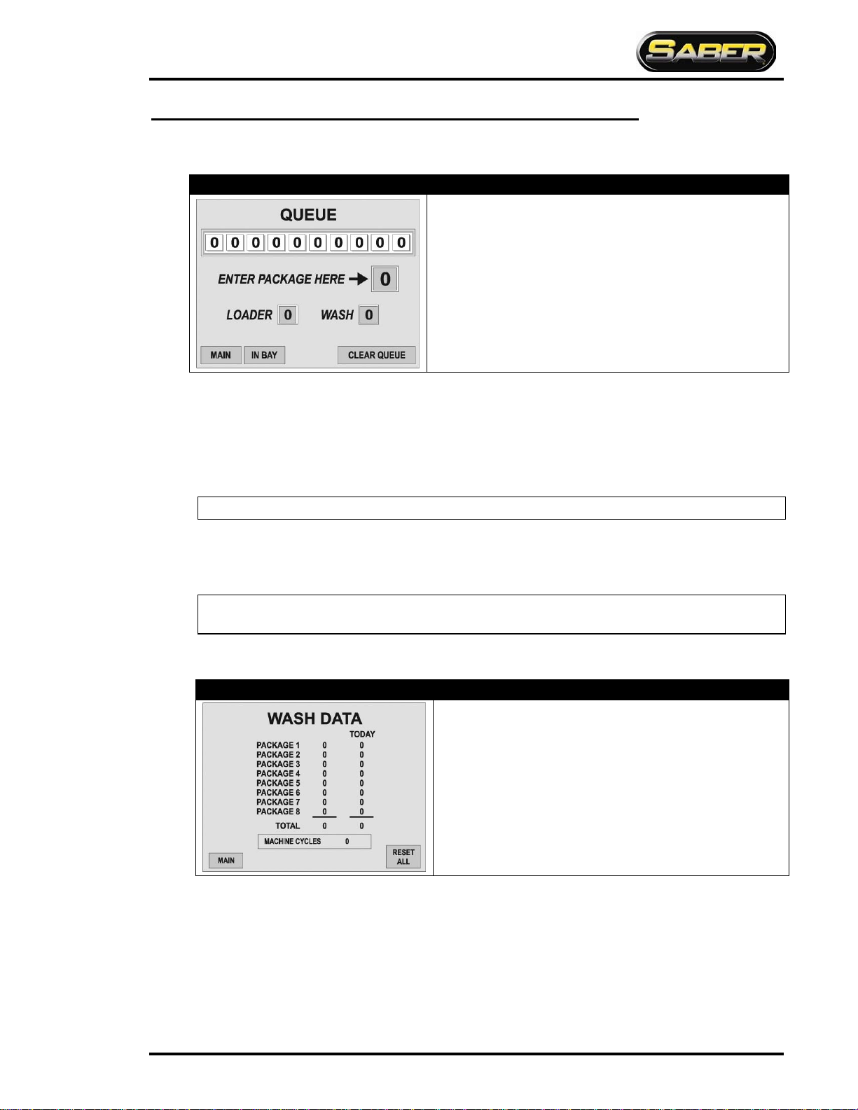
Queue
Chapter 1 Operator Interface/Standard User Screens
E-1063
Screen Key
•
The row of boxes displays the ten packages in QUEUE, 0 if not
present
•The field to the right of the arrow is where you will enter the next
available Package
•“Loader”shows the wash that is being evaluated to load
•“Wash” shows the vehicle that has been pulled from loader.
typically occurs when the vehicle has entered the Photo-Eye beam
The Queue keeps track of the packages that vehicles will receive. It can keep track of up to 10 vehicles at a time.
Package selections can be entered into the “Queue” from the screen ONLY. The POS will enter selections directly
into the Loader.
Values entered into the Queue will be inserted to the right of the last position entered. If package is the first entered
into Queue, it will be inserted into the left most position. As washes are used, the Queue will shift all packages tothe
left one place until all washes are shifted into the Loader.
Note: POS will NOT use QUEUE; it will insert selections directly into the Loader.
When the system is ready to accept another vehicle into the wash, the Loader will be shifted into wash if Entrance
operation 1 “On Condition”is met.
Entrance Operation 1 will need to be configured even if not used in packages.
Note: See Entrance Operation 1 for conditions to move package from Loader to
wash.
Data
E-1063 Screen Key
•The middle column displays total of each package used since last
package reset
•Today Column displays total of each package used since
midnight
•Total Field displays total of combined packages until “Total Reset”
•Cycles Field displays total of combined packages that are “Non
Re-settable”
The middle column shows accumulation of packages since lasttime the Package Reset was pressed.
The “Today” column shows accumulation of packages since midnight.
Pressing “Reset All” will clear the values of the total data and package data accumulated since Reset All was last
pressed.
SL2: 1063 PROGRAMMING AND OPERATION
1-2 Belanger, Inc. * PO BOX 5470 * Northville, MI 48167-5470 * Ph (248) 349-7010 * Fax (248) 380-9681 1MANUL294
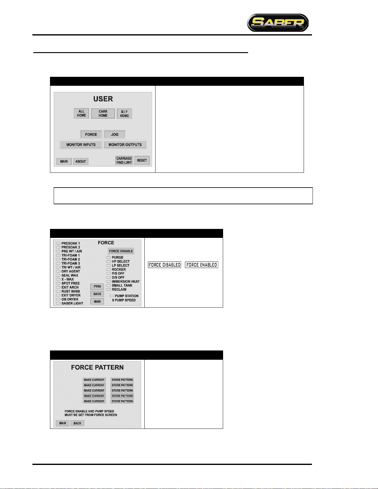
User
Chapter 1 Operator Interface/Standard User Screens
E-1063
Screen Key
•
All Home: Homes the machine without Reset
•Carriage Home: Homes the Carriage ONLY
•Butterfly Home: Homes the Butterfly ONLY
•Force: Moves you to the Force screen
•Jog: Moves you to the Jog screen
•Monitor inputs: Moves you to the Monitor Inputs screen
•Monitor Outputs: Moves you to the Monitor Outputs screen
•About: Moves you to the About screen
•Carriage Find Limit: Causes the machine to locate Entrance and
Exit limit
•Reset: Resets and Homes machine
Machine MUST be in Home position to perform a “Carriage Find Limit”.
Note: The Carriage Find Limit must be performed on a machine that is a new install before any vehicles are
washed. This function typically doesnot need to be performed again afterit has been completed once.
If pressing the reset button does not reset the machine, check Fault screen for reoccurring fault.
User / Force
E-1063 Screen Key
Pressing the Force Enabled/Force
Disabled toggle button alternates
between the fields shown below:
/
To force an Application, fill in the ovals next to the desired Outputs. Enter the pump speed, then toggle between
“Force Enabled/Disabled”. The pump speed may be zero for some applications.
To turn off Force, press the “Force Enabled/Disabled” toggle button.
User / Force / Ptrn
E-1063 Screen Key
Pressing the PTRN (Pattern) key
moves you to this screen
Due to the flexibility of this system, dedicated FORCE applications are not provided. This screen consists of five
nameable FORCE patterns. To utilize, set a pattern on the FORCE screen. Next move to this screen and press
STORE PATTERN. Now you are to name the Pattern. To use the stored Pattern in the future, press the MAKE
CURRENT button.
SL2: 1063 PROGRAMMING AND OPERATION
1MANUL294 Belanger, Inc. * PO BOX 5470 * Northville, MI 48167-5470 * Ph (248) 349-7010 * Fax (248) 380-9681 1-3
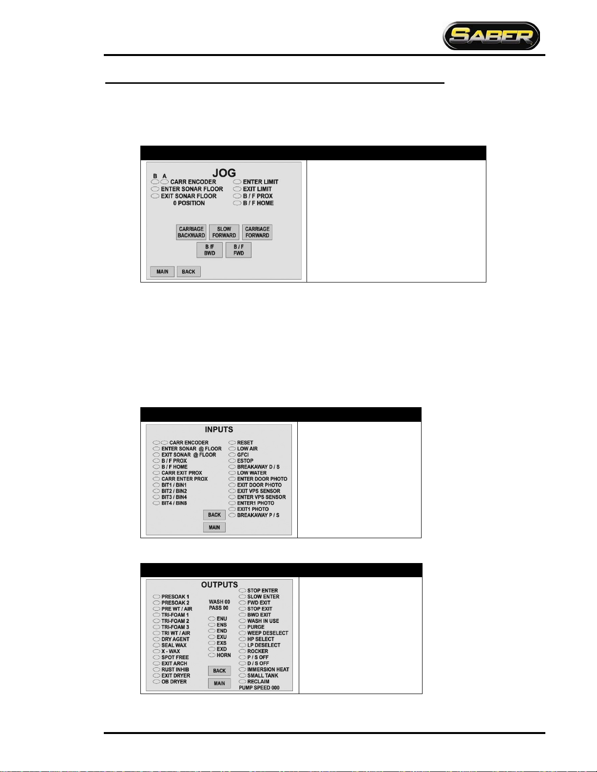
User / Jog
Chapter 1 Operator Interface/Standard User Screens
User
E-1063
Screen Key
•
Carriage Backward: Jogs carriage towards
entrance while pressed
•Carriage Forward: Jogs carriage towards exit
while pressed
•Slow Forward: Jogs carriage towards exit slower
than Carriage Forward while pressed
•B/F FWD: Jogs butterfly towards exit
•B/F BWD: Jogs butterfly towards entrance
Slow Forward:has been provided to check proper carriage Encoder operation. Pressing this button first begins
the Carriage moving slowly down the rails causing the gear in the Encoder to turn. This should make the ovals
next to “CARR ENCODER” fill from left to right and clear from left to right. If the oval fill/clear pattern is not
according to the above, first check wiring. A typical fix if pattern is reversed is to swap Proximity Cables on the
Encoder.
Pressing and holding the SLOW FWD button will cause the display to appear for A and B Phase Encoder on
times. The proximity sensors should be adjusted until these are nearly identical. Typically 0.500 is displayed for
proper setting when the Proximity Switch gap is set between .040 and .056 inches.
User / Monitor Inputs
E-1063
Screen Key
•
The ovals are ON/OFF
indicators
•A filled oval indicates that an
Input is ON
User / Monitor Outputs
E-1063 Screen Key
•
The ovals are ON/OFF
indicators
•A filled oval indicates that an
Output is ON
•Some Outputs are namable and
will not be the same as names
indicated to the left

SL2: 1063 PROGRAMMING AND OPERATION
1-4 Belanger, Inc. * PO BOX 5470 * Northville, MI 48167-5470 * Ph (248) 349-7010 * Fax (248) 380-9681 1MANUL294
User / About
Chapter 1 Operator Interface/Standard User Screens
User
E-1063
Screen Key
•
The number displayed to the right of “Screen
Software”shows the version of software in your
Operator Interface
•The number displayed to the right of “Logic
Software”shows the version of software in your
Controller (PLC)
Wash Data:has been provided as a way to view what is in the “Wash Data” screen without any reset capability.
Faults
E-1063 Screen Key
•
The ovals are ON/OFF indicators
•A filled oval indicates that Fault is active
•Reset: Resets and Homes machine
•Alarms: Move to the Alarm screen
•Clear Alarms: Resets alarms shown on the Alarm
screen
•More: Moves you to the Capture screen
This screen displays a current Fault status on the system. The oval next to a particular Fault will be filled when that
Fault is active. It also displays a numerical Fault status of the system. This is the 4-digit “Error Code” that will be sent
to a pager when Fault occurs.
The “DRIVE CODE” field is covered on the next page.
Note: FAULT status 255 is for “System Ok”.
Note: See Chapter 6 for Fault Information.

SL2: 1063 PROGRAMMING AND OPERATION
1MANUL294 Belanger, Inc. * PO BOX 5470 * Northville, MI 48167-5470 * Ph (248) 349-7010 * Fax (248) 380-9681 1-5
Faults / Alarms
Chapter 1 Operator interface/Machine Operation
Faults
E-1063
Screen Key
Returns to the Fault screen
Scrolls up list
Not used
Changes font size of list
Displays time and date on screen
Scrolls down list
Faults / More (Capture)
E-1063
Screen Key
•Displays some of the status and conditions of the machine at the
instant it last faulted or the Capture button was pressed
•Pressing the Auto Capture toggle button alternated between the fields
shown below: /
•Capture: captures (updates) status and conditions at the instant button
is pressed


Chapter 2 General Methods of Using Operator Interfaces
Chapter 2
General Methods of
Using Operator
Interfaces

SL2: 1063 PROGRAMMING AND OPERATION
1MANUL294 Belanger, Inc. * PO BOX 5470 * Northville, MI 48167-5470 * Ph (248) 349-7010 * Fax (248) 380-9681 2-1
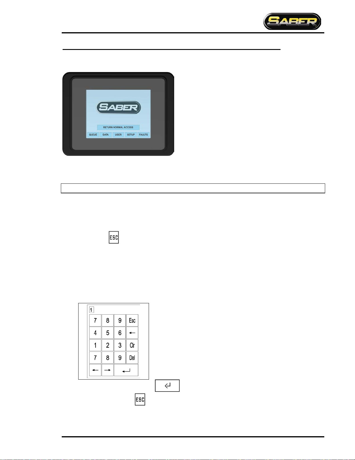
E-1063
Chapter 2 General Methods of Using Operator Interfaces
The E-1063 is an Operator interface that utilized “Touch-Screen” technology. User makes selections and enters data by
touching the appropriate positions on the screen. Due to the ease in which a stylus can be misplaced, we recommend that
you use the back end of an ink pen or a stylus.
Note: It is not recommended that the screen be operated with metal objects such as keys or screw-drivers.
Fields encountered on this unit are as follows:
Screen Navigation
The Screen Navigation fields are typically located at the bottom of the screen. These fields typically have frames
(boxes) around words. Pressing these fields will change current screen to the corresponding screen. Some screen
require pressing to return to the previous screen.
Toggles
These fields toggle between two values when pressed. Typical data in these fields is YES/NO, ENABLED/DISABLED
and choosing between two different numbers. These fields may be just the changeable value or the entire line. It may
require pressing a few different locations on the line to find the toggle field.
Numeric
When a field is selected that is Numeric the following Data Entry Screen will appear.
When done entering the data, press .to return to the original screen. To leave the Data Entry screens
without changing data, press .
SL2: 1063 PROGRAMMING AND OPERATION
2-2 Belanger, Inc. * PO BOX 5470 * Northville, MI 48167-5470 * Ph (248) 349-7010 * Fax (248) 380-9681 1MANUL294
Chapter 2 General Methods of Using Operator Interfaces
E-1063
Selections
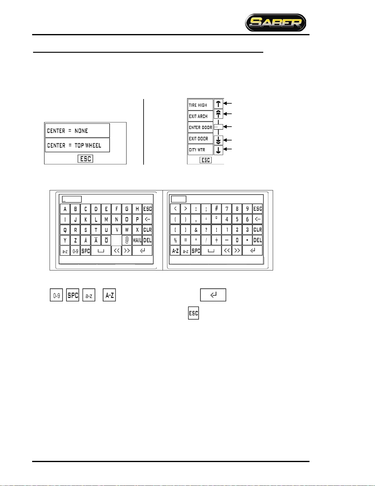
When a field is selected that is of “Type” Selection, screens that resemble the following will appear:
Alpha/Numeric
•When a field is selected that is Alpha/Numeric one of the following Data Entry Screens will appear:
To navigate between screens press on of the following:
, , or . When done entering the data, press .to return to the original screen.
To leave the Data Entry screens without changing data, press .
If the available
selectionsare
more than
what will fit in a
single screen,
scroll controls
will appear to
the right of the
selection.
Up one selection
Up to limit
Slider
Down to limit
Down one selection
Screen with allselections visible
Table of contents
Other Belanger Industrial Equipment manuals


Popular Industrial Equipment manuals by other brands

WDT
WDT Granudos 45/100-Touch Operating and installation instructions

ABB
ABB HT573162 Operation manual

PR electronics
PR electronics 6185 product manual

Marshall Excelsior
Marshall Excelsior MER470 STANDARD KIT Important installation instructions

Panasonic
Panasonic EXC14CG quick start guide

ABB
ABB HT568171 Operation manual


